Table of Contents
Advertisement
Quick Links
This .pdf document is bookmarked
Operation and Maintenance Instructions
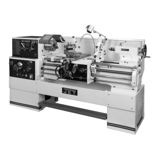
GH-1640ZK Lathe
For ZK Lathe Parts List and Electrical Diagrams, see document M-321850-1
WALTER MEIER (Manufacturing) Inc.
427 New Sanford Road
LaVergne, Tennessee 37086
Part No. M-321850
Ph.: 800-274-6848
Revision B 02/2013
www.waltermeier.com
Copyright © 2013 Walter Meier (Manufacturing) Inc.
Advertisement
Chapters
Table of Contents

Related Manuals for Jet GH-1640ZK


Summary of Contents for Jet GH-1640ZK
- Page 1 This .pdf document is bookmarked Operation and Maintenance Instructions GH-1640ZK Lathe For ZK Lathe Parts List and Electrical Diagrams, see document M-321850-1 WALTER MEIER (Manufacturing) Inc. 427 New Sanford Road LaVergne, Tennessee 37086 Part No. M-321850 Ph.: 800-274-6848 Revision B 02/2013 www.waltermeier.com...
-
Page 2: Warranty And Service
Walter Meier is consistently adding new products to the line. For complete, up-to-date product information, check with your local Walter Meier distributor, or visit jettools.com. WARRANTY JET products carry a limited warranty which varies in duration based upon the product (MW = Metalworking, WW = Woodworking). WHAT IS COVERED? This warranty covers any defects in workmanship or materials subject to the exceptions stated below. -
Page 3: Table Of Contents
2.0 Table of Contents 1.0 Warranty and Service ............................. 2 2.0 Table of Contents ..............................3 3.0 Safety warnings ..............................4 4.0 Specifications ................................. 6 5.0 Dimensions and mounting hole centers ......................... 7 6.0 General Description and Nomenclature ......................... 8 ... -
Page 4: Safety Warnings
3.0 Safety warnings Read and understand the entire owner’s manual before attempting assembly or operation. Read and understand the warnings posted on the machine and in this manual. Failure to comply with all of these warnings may cause serious injury. Replace the warning labels if they become obscured or removed. - Page 5 24. Use the right tool at the correct speed and feed rate. Do not force a tool or attachment to do a job for which it was not designed. The right tool will do the job better and more safely. 25.
-
Page 6: Specifications
4.0 Specifications Model Number ............................GH-1640ZK Stock Number ..............................321850 General Capacities: Maximum Swing over Bed ........................16” (406mm) Maximum Swing over Cross Slide .......................10” (254mm) Maximum Swing Through Gap ....................23-7/32” (590mm) Length of Gap ..........................10-5/8” (270mm) Distance between Centers ........................ 40” (1016mm) Width of Bed ........................... -
Page 7: Dimensions And Mounting Hole Centers
Range of Modular Threads ........................0.25-10M.P. Leadscrew Pitch .............................. 1/4” Tailstock: Tailstock Spindle Travel ........................6” (152.4mm) Tailstock Taper.............................. MT-4 Maximum Tailstock Cross Displacement ..................+/- 0.40” (10mm) Other: Steady Rest Capacity ......................3/8 - 4” (9.5 x 102mm) Follow Rest Capacity ....................1/2" – 3-1/8” (12.7 x 79.4mm) Coolant tank capacity (approximate) ..................... -
Page 8: General Description And Nomenclature
6.0 General Description and Nomenclature Figure 2 – General Description Bed and stand eliminating the need for gear changes except where special threading is required. The lathe bed (A) is made of cast iron with low Carriage vibration and high rigidity. Two precision-ground v- slideways (B), reinforced by supersonic frequency The carriage assembly is composed of the Apron, hardening,... - Page 9 Tailstock Follow rest (T) The tailstock (L) slides on a v-way and can be The traveling follow rest is mounted to the saddle, locked at any location by a clamping lever. The and thus follows the movement of the turning tool. tailstock has a heavy duty quill with a No. 4 Morse Only two fingers are required as the place of the Taper and etched graduation scale.
-
Page 10: Unpacking
Live Center, MT-4 – F Dead Center, MT-4 – G NOTE: Optional accessories are available for JET Lathes, such as Taper Attachment, Collet Closer and Digital Read Out. Contact your dealer or Walter Meier (Manufacturing) Inc., for more information. Figure 3... -
Page 11: Installation
nuts. Or, it may be secured to the floor using Read and understand the bolts placed head-down in the concrete, and entire contents this manual before using shims where needed to level the attempting set-up or operation. Failure to machine. Refer to Figure 1 for mounting hole comply may cause serious injury. -
Page 12: Chuck Preparation
8.3 Chuck preparation 5. Lift the chuck up to the spindle nose and press onto the spindle. Tighten in place by turning the camlocks 1/4 turn clockwise. The index Read and understand all mark (A, Figure 7) on the camlock should be directions for chuck preparation. -
Page 13: Maintenance/Lubrication
9.0 Maintenance/Lubrication Lathe must be serviced at all lubrication points and all reservoirs filled to operating level before the lathe is put into service. Failure to comply may cause serious damage to the lathe. The ZK series lathe is shipped with oil in the reservoirs. -
Page 14: Ball Oiler Locations
4. Apron – Oil must be between indicator marks in the oil sight glass (G, Figure 11). Top off with SAE 20W oil. Unscrew oil plug (H, Figure 11) to fill. To drain, remove drain plug on the underside of apron. Drain oil completely and refill after the first three months of operation. -
Page 15: Coolant Preparation
Figure 17 Figure 15 – Lubrication points 10.0 Electrical connections 13. Tailstock – Daily lubricate two ball oilers (Figure 16) on top of tailstock. Electrical connections must The anti-dust felt beneath the tailstock that made qualified electrician runs along the ways should be cleaned weekly compliance with all relevant codes. -
Page 16: Basic Controls
11.0 Basic controls Figure 20 – Carriage controls and settings 5. Carriage Lock (J, Figure 20): Located on top right of carriage. Turn clockwise to lock, Figure 19 – Headstock Controls counterclockwise to unlock. 1. Control Panel: Located on front of headstock. •... - Page 17 adjustment is ever needed, follow the diagram on the front of apron. Only qualified personnel should make clutch adjustments. 12. Threading Dial (Q, Figure 20): Indicates the point on the leadscrew where the half nut can be re-engaged to continue inch threading. 13.
-
Page 18: Operation
12.0 Operation The operator should consult shop manuals such as “Machinery’s Handbook” for cutting speeds and feeds appropriate to specific workpieces. Correct feed depends upon material to be cut, cutting operation, tool type, chucking rigidity, depth of cut, and desired surface quality. IMPORTANT: Allow a break-in period for the new lathe so that gears and bearings can adapt;... -
Page 19: Spindle Speed
12.2 Spindle speed Twelve speeds are available by positioning the two speed levers (F, Figure 27) according to the accompanying chart on the front of the headstock. You may need to turn the chuck by hand to assist engagement of the gears. Never change speed while spindle is turning. -
Page 20: Adjustments
13.0 Adjustments Adjustments to the lathe, especially those involving alignments bearings, spindle, leadscrew, clutch, etc., should only performed qualified personnel, as improper alignments can damage the machine and/or create a safety hazard. Turn off main switch and press emergency stop button before making adjustments to lathe. -
Page 21: Gap Section
short period of use; and prolonged use will require that they be tightened to compensate for normal wear. NOTE: If a worn, cracked or frayed belt needs replacing, replace all three as a matched set. To adjust or replace belts: 1. -
Page 22: Cross Slide Nut Adjustment
1. Loosen hex nut (A) to slide steady rest along the ways. 2. Loosen knurled handle (B) until it can be pivoted out of the slot. 3. Loosen three lock knobs (C), and back off the fingers (D) using knurled handles (E). 4. -
Page 23: Troubleshooting The Zk Series Lathe
14.0 Troubleshooting the ZK series lathe Table 2 Trouble Probable Cause Remedy Verify incoming power, main leads, main No electrical power, or wiring incorrect. switch is on. Emergency stop switch is pressed. Rotate switch clockwise to release. End gear cover open, limit switch Close cover. -
Page 24: Lubrication Schedule And General Maintenance
15.0 Lubrication schedule and general maintenance Regularly scheduled maintenance is crucial to ensure a long service life for your machine. The schedule below shows general cleaning, lubrication points and coolant replacement information for the ZH Series Lathes. Push stop button and power off before lubricating. -
Page 25: Reference Tables
16.0 Reference Tables 16.1 Inch Lead And Feed Table 4 = metric threads = inch threads m = modular threads DP = diametral threads... - Page 26 This page intentionally left blank...
- Page 27 This page intentionally left blank...
- Page 28 WALTER MEIER (Manufacturing) Inc. 427 New Sanford Road LaVergne, Tennessee 37086 Phone: 800-274-6848 www.jettools.com www.waltermeier.com...
- Page 29 This .pdf document is bookmarked Parts List and Electrical Diagrams GH-1640ZK Lathe For ZK Lathe Operation and Maintenance Instructions, see document M-321850 WALTER MEIER (Manufacturing) Inc. 427 New Sanford Road LaVergne, Tennessee 37086 Part No. M-321850-1 Ph.: 800-274-6848 Revision B 02/2013 www.waltermeier.com...
- Page 30 Walter Meier is consistently adding new products to the line. For complete, up-to-date product information, check with your local Walter Meier distributor, or visit.jettools.com. WARRANTY JET products carry a limited warranty which varies in duration based upon the product (MW = Metalworking, WW = Woodworking). WHAT IS COVERED? This warranty covers any defects in workmanship or materials subject to the exceptions stated below.
- Page 31 2.0 Table of Contents Section Page 1.0 Warranty and Service ............................. 2 2.0 Table of Contents ............................3 3.0 Stand Assembly – Exploded View ......................... 4 3.1 Stand Assembly – Parts List .......................... 5 4.0 Brake Assembly – Exploded View ......................... 6 ...
-
Page 32: Stand Assembly - Exploded View
3.0 Stand Assembly – Exploded View... -
Page 33: Stand Assembly - Parts List
38 ....1640ZK-138 ....Drain Plug ............Z1/4........2 39 ....1640ZK-139 ....Coolant Level Indicator .................. 1 40 ....TS-155010 ....Washer ............. M16 ........1 ....STRIPE-1-3/4 .... JET stripe (not shown) ........1-3/4”W ......per ft. -
Page 34: Brake Assembly - Exploded View
4.0 Brake Assembly – Exploded View... -
Page 35: Brake Assembly - Parts List
4.1 Brake Assembly – Parts List Index No. Part No. Description Size 1 ....ZX-22101 ....Fork........................ 1 2 ....ZX-S41 ...... Spring Pin ............5x40 mm ......1 3 ....TS-1540061 ....Hex Nut ............. M8 ........4 4 ....ZX-22707A ....Butt Rod Support ................... 2 5 .... -
Page 36: Bed Assembly - Exploded View
5.0 Bed Assembly – Exploded View... -
Page 37: Bed Assembly - Parts List
5.1 Bed Assembly – Parts List Index No. Part No. Description Size 1 ....1640ZK-301 ....Bed ........................ 1 2 ....1640ZK-302 ....Washer ............. B16 ........8 3 ....1640ZK-303 ....Hex Cap Bolt............. M16x45 ........ 8 4 ....1640ZK-304 ....Rack....................... 1 5 .... - Page 38 Index No. Part No. Description Size 64 ....1640ZK-364 ....Bracket......................1 65 ....TS-1482031 ....Hex Cap Screw ..........M6x16 ........2 66 ....1640ZK-366 ....Cover ......................1 67 ....ZX-B60 ...... Cross Recessed Pan Head Screw ....M6x18 ........4 68 ....
-
Page 39: Headstock Assembly I - Exploded View
6.0 Headstock Assembly I – Exploded View... -
Page 40: Headstock Assembly I - Parts List
6.1 Headstock Assembly I – Parts List Index No. Part No. Description Size 1 ....1640ZK-401 ....Round Sign Plate ................... 3 2 ....ZX-H3 ......Flat End Set Screw ........... M10x12 ........ 3 3 ....ZX-H4 ......Spring ............... YI-1x8x25......1 4 .... -
Page 41: Headstock Assembly Ii - Exploded View
7.0 Headstock Assembly II – Exploded View... -
Page 42: Headstock Assembly Ii - Parts List
7.1 Headstock Assembly II – Parts List Index No. Part No. Description Size 57 ....TS-1524041 ....Set Screw ............M8x16 ........2 58 ....1640ZK-558 ....Round Clamp Nut ..................1 59 ....ZX-H60B ....V-Belt ......................4 60 .... - Page 43 Index No. Part No. Description Size 116 .... TS-1505031 ....Hex Socket Cap Screw ........M10x25 ........ 1 119 .... 1640ZK-5119 .... Sleeve ......................1 120 .... ZX-H198 ....C-Clip ..............28 mm ........2 121 .... GB1096-5x12 .... Flat Key............. 5x12 mm ......1 122 ....
-
Page 44: Headstock Assembly Iii - Exploded View
8.0 Headstock Assembly III – Exploded View... -
Page 45: Headstock Assembly Iii - Parts List
8.1 Headstock Assembly III – Parts List Index No. Part No. Description Size 2 ....ZX-H3 ......Flat End Set Screw ........... M10x12 ........ 3 126 .... 1640ZK-6126 .... Locking Block....................1 127 .... 1640ZK-6127 .... Round Nut...................... 1 128 .... -
Page 46: Headstock Assembly Iv - Exploded View
9.0 Headstock Assembly IV – Exploded View... -
Page 47: Headstock Assembly Iv - Parts List
9.1 Headstock Assembly IV – Parts List Index No. Part No. Description Size 64 ....TS-1503011 ....Hex Socket Cap Screw ........M6x8 ........4 65 ....TS-1504021 ....Hex Socket Cap Screw ........M8x12 ........4 85 ....TS-1503041 ....Hex Socket Cap Screw ........M6x16 ........8 158 .... -
Page 48: Change Gear Box Assembly I - Exploded View
10.0 Change Gear Box Assembly I – Exploded View... -
Page 49: Change Gear Box Assembly I - Parts List
10.1 Change Gear Box Assembly I – Parts List Index No. Part No. Description Size 1 ....ZX-08101 ....Change Gear Box Casting ................1 2 ....ZX-08108 ....Front Cover ....................1 3 ....C6140ZK-08703 ..Splash Guard ....................1 4 .... -
Page 50: Change Gear Box Assembly Ii - Exploded View
11.0 Change Gear Box Assembly II – Exploded View... -
Page 51: Change Gear Box Assembly Ii - Parts List
11.1 Change Gear Box Assembly II – Parts List Index No. Part No. Description Size 3 ....ZX-08104 ....End Cover ...................... 4 4 ....ZX-08103 ....Bearing Support ..................... 1 19 ....ZX-08107 ....Gear ..............3m36T........1 20 .... -
Page 52: Quick Change Gear Box I - Exploded View
12.0 Quick Change Gear Box I – Exploded View... -
Page 53: Quick Change Gear Box I - Parts List
12.1 Quick Change Gear Box I – Parts List Index No. Part No. Description Size 1 ....1640ZK-1001 .... Upper Cover ....................1 2 ....TS-1503061 ....Hex Socket Cap Screw ........M6x25 ........2 6 ....TS-1504031 ....Hex Socket Cap Screw ........M8x16 ........ 10 7 .... - Page 54 Index No. Part No. Description Size 66 ....ZX-Q66...... Taper Pin ............5x35 mm ......6 67 ....1640ZK-1067 .... Gear Box Sign Plate ..................1 68 ....ZX-S27 ...... Cross Head Screw ..........M5x8 ........4 69 ....ZX-Q69...... Oil Sight Glass ..........20 ......... 1 70 ....
-
Page 55: Quick Change Gear Box Ii - Exploded View
13.0 Quick Change Gear Box II – Exploded View... -
Page 56: Quick Change Gear Box Ii - Parts List
13.1 Quick Change Gear Box II – Parts List Index No. Part No. Description Size 81 ....ZX-05104 ....Middle Bearing Support ................. 2 82 ....ZX-Q82...... Taper End Set Screw........M10x16 ........ 2 83 ....ZX-B23 ...... C-Clip ..............20 mm ........1 84 .... -
Page 57: Quick Change Gear Box Iii - Exploded View
14.0 Quick Change Gear Box III – Exploded View... -
Page 58: Quick Change Gear Box Iii - Parts List
14.1 Quick Change Gear Box III – Parts List Index No. Part No. Description Size 66 ....ZX-Q66...... Taper Pin ............5x35 mm ......6 83 ....ZX-Q83...... C-Clip ..............20 mm ........3 84 ....ZX-Q84...... C-Clip ..............42 mm ........5 85 .... -
Page 59: Apron Assembly I - Exploded View
15.0 Apron Assembly I – Exploded View... -
Page 60: Apron Assembly I - Parts List
15.1 Apron Assembly I – Parts List Index No. Part No. Description Size 1 ....1640ZK-1301 .... Apron Casting ....................1 2 ....1640ZK-1302 .... Bottom Cover ....................1 3 ....TS-1540072 ....Hex Nut ............. M10 ........1 4 .... - Page 61 Index No. Part No. Description Size 139 .... ZX-A139 ....Oil Conducting Cord ......... 3x100 mm ......2 140 .... ZX-A140 ....Screw ..............M10x40 ........ 1 158 .... TS-1540041 ....Hex Nut ............. M6 ........1 159 .... TL06124 ....Bracket......................1 160 ....
-
Page 62: Apron Assembly Ii - Exploded View
16.0 Apron Assembly II – Exploded View... -
Page 63: Apron Assembly Ii - Parts List
16.1 Apron Assembly II – Parts List Index No. Part No. Description Size 38 ....ZX-B23 ...... C-Clip ..............20mm ........1 39 ....BB-6204 ....Ball Bearing ............20x47x14 ......1 40 ....TL06705 ....Gear ..............2m65T........1 41 ....ZX-A41 ...... Taper Pin ............6x40mm ....... 1 42 .... - Page 64 Index No. Part No. Description Size 104 .... ZX-A104 ....Flat Head Set Screw ......... M4x8 ........1 105 .... TL06301 ....Sleeve ......................1 106 .... TL06710 ....Gear ..............2m21T/2m57T ..... 1 107 .... ZX-A107 ....Pin..............6n6x8 ........1 108 ....
-
Page 65: Apron Assembly Iii (Threading Dial) - Exploded View
17.0 Apron Assembly III (Threading Dial) – Exploded View... -
Page 66: Apron Assembly Iii (Threading Dial) - Parts List
17.1 Apron Assembly III (Threading Dial) – Parts List Index No. Part No. Description Size 134 .... ZX-A141 ....Half Round Head Screw ........M6x18 ........1 135 .... ZX-11704 ....Washer ......................1 136 .... 1640ZK-15136 ..Dial (inch)....................... 1 137 .... -
Page 67: Saddle And Cross Slide Assembly - Exploded View
18.0 Saddle and Cross Slide Assembly – Exploded View... -
Page 68: Saddle And Cross Slide Assembly - Parts List
18.1 Saddle and Cross Slide Assembly – Parts List Index No. Part No. Description Size 1 ....1640ZK-1601 .... Saddle Casting ....................1 2 ....GB1155-10 ....Oil Cup .............. 10 mm ........7 3 ....1640ZK-1603 .... Wipe Plate ..................... 1 4 .... - Page 69 Index No. Part No. Description Size 61 ....ZX-04790 ....Pushing Rod ....................1 62 ....ZX-04788 ....Stop Pin ......................1 63 ....ZX-04507 ....Stop Pin Cap....................1 64 ....ZX-04769 ....Sleeve ......................1 65 ....
-
Page 70: Tool Post And Compound Rest - Exploded View
19.0 Tool Post and Compound Rest – Exploded View... -
Page 71: Tool Post And Compound Rest - Parts List
19.1 Tool Post and Compound Rest – Parts List Index No. Part No. Description Size 1 ....ZX-04103B ....Revolving Plate ....................1 2 ....ZX-04725 ....Screw ......................1 3 ....1640ZK-1703 .... Gib ......................... 1 4 ....ZX-04786 ....Screw ......................1 5 .... -
Page 72: Tailstock Assembly I - Exploded View
20.0 Tailstock Assembly I – Exploded View... -
Page 73: Tailstock Assembly I - Parts List
20.1 Tailstock Assembly I – Parts List Index No. Part No. Description Size 1 ....1640ZK-1801 .... Handle ......................1 2 ....ZX-T36 ...... Taper Pin ............6x32 mm ......1 3 ....1640ZK-1803 .... Lever Support ....................1 4 .... -
Page 74: Tailstock Assembly Ii - Exploded View
21.0 Tailstock Assembly II – Exploded View 21.1 Tailstock Assembly II – Parts List Index No. Part No. Description Size 42 ....1640ZK-1942 .... Sliding Base ....................1 43 ....GB70-8x80 ....Hex Socket Cap Screw ........M8x80 ........2 44 .... -
Page 75: Steady Rest Assembly - Exploded View
22.0 Steady Rest Assembly – Exploded View... -
Page 76: Steady Rest Assembly - Parts List
22.1 Steady Rest Assembly – Parts List Index No. Part No. Description Size Qty ....1640ZK-SRA ..... Steady Rest Assembly 16” (index #1-17) ............1 1 ....1640ZK-2001 .... Screw ......................3 2 ....1640ZK-2002 .... Sliding Sleeve ....................3 3 .... -
Page 77: Follow Rest Assembly - Exploded View
23.0 Follow Rest Assembly – Exploded View 23.1 Follow Rest Assembly – Parts List Index No. Part No. Description Size Qty ....ZK-FRA16 ....Follow Rest Assembly (index #1-9) ............... 1 1 ....1640ZK-2101 .... Screw ......................2 2 ....1640ZK-2102 .... Nut ......................... 2 3 .... -
Page 78: Coolant And Work Light Assembly - Exploded View
24.0 Coolant and Work Light Assembly – Exploded View... -
Page 79: Coolant And Work Light Assembly - Parts List
24.1 Coolant and Work Light Assembly – Parts List Index No. Part No. Description Size 1 ....RT-001B ....Rubber Tube ............ID 1/2" x 1780 ....1 2 ....TS-1481061 ....Hex Cap Screw ............M5x25 ......4 3 ....TS1540031....Hex Nut ..............M5 ......... 4 4 .... -
Page 80: Chuck Guard Assembly - Exploded View
26.0 Chuck Guard Assembly – Exploded View 26.1 Chuck Guard Assembly – Parts List Index No. Part No. Description Size Qty ....ZK-CGA..... Chuck Guard Assembly (# 1 thru 21) ............1 1 ....ZX-19701E ....Protection Guard.................... 1 2 ....ZX-19501E ....Protection Guard Visual Glass............... 1 3 .... -
Page 81: Toolbox, Accessories, And Attachments
W ....TNMP08501A.... Gear * ..............3.5m36T ......1 X ..........Adjustable Wrench * ..................1 Y ....ZX-OP-10 ....Touchup Paint Can (JET White) *..............1 Z ....ZX-OP-09 ....Oil Gun * ......................1... -
Page 82: Electrical Components - Parts List
28.0 Electrical Components – Parts List (Index numbers are shown below; diagram numbers are shown on following page.) Index No. Diagram No. Part No. Description Size 1....HL ....ZK-HL ....Power Indicator Light ......AD11-30/20 ......1 2 ....SA2 ....ZX-SA2 .... Coolant Pump Switch ......LAY3-11X/2 ......1 3 .... -
Page 83: Electrical Diagram
28.1 Electrical Diagram GH-1640ZK Lathe, 3PH/230V... -
Page 84: Rotary Switch Diagram
28.2 Rotary Switch Diagram 29.0 Ordering Replacement Parts To order parts or reach our service department, call 1-800-274-6848, Monday through Friday (see our website for business hours, www.jettools.com). Having the Model Number and Serial Number of your machine available when you call will allow us to serve you quickly and accurately.