Table of Contents
Advertisement
Advertisement
Table of Contents

Related Manuals for Baldor OHV Series 3KW-9KW


Summary of Contents for Baldor OHV Series 3KW-9KW
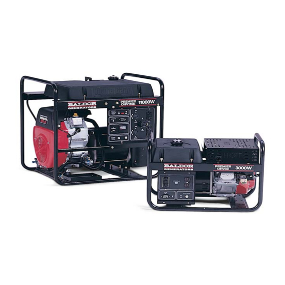
- Page 1 OPERATOR'S MANUAL FOR YOUR PREMIER POW’R PRODUCTS GENERATORS OHV Series 3KW-9KW BALDOR GENERATORS 3815 Oregon. Street • Oshkosh WI 54902 Telephone 236-4200 • Fax 920-236-4219 FORM#: S-PSG-002-7 EFFECTIVE DATE: 4/4/97 OHV SERIES COVER\MSW'00 REVISION DATE: 9/24/02...
- Page 2 DO NOT OPERATE THIS GENERATOR SET UNTIL YOU CAREFULLY READ THIS MANUAL AND UNDERSTAND THE SAFETY WARNINGS AND INSTRUCTIONS CONTAINED IN IT. While safety is built into every Baldor Pow'R Gard generator set, careless or improper operation could possibly result in mechanical failure, property damage, severe injury or even death.
- Page 3 ♦ Place protective covers and guards over the rotating parts, if rotating parts such as the drive shaft, pulley, belt, etc. are left exposed, they are potentially hazardous. ♦ When cleaning, repairing or inspecting, make sure all moving parts have stopped. ♦...
- Page 4 ♦ Know how to stop the engine quickly and understand the operation of all controls. ♦ Never permit anyone to operate the generator set without proper instructions. ♦ Never allow children to operate the generator set. ♦ Children and pets must be kept away from the area of operation due to the possibility of burns from hot engine components or injury from any equipment the generator set is powering.
- Page 5 ♦ Always treat the electrical circuits as if they were energized. ♦ Disconnect all leads plugged into the unit Prior to working on it. ♦ Have the electrical circuits serviced only by qualified technicians. ♦ Inspect wiring frequently and replace frayed, broken or poor leads. ♦...
- Page 6 Operation inside an enclosed compartment or building is a potential fire hazard and should not be done unless approval is obtained from Baldor Generators. Engine/Generator overheating can cause severe damage due to restricted, obstructed or improper air-flow that is necessary for the proper cooling of the unit.
-
Page 7: Table Of Contents
TABLE OF CONTENTS SECTION PAGE Basic Location Information…………………………………………………………………………………………………..1 Basic Connection Information……………………………………………………………………………………………..2 Basic Engine Information………………………………………………………………………………………………………….3 Generator End Maintenance……………………………………………………………………………………………………..4 Basic Engine Maintenance………………………………………………………………………………………………………..5 Storage Instructions…………………………………………………………………………………………………………………..6 Electric Motor Loads…………………………………………………………………………………………………………………….7 Parts & Service Information………………………………………………………………………………………………….8 Operation………………………………………………………………………………………………………………………………………………..9 Simple Electrical Troubleshooting………………………………………………………………………………….11 Control Panel Information for OHV30…………………………………………………………………………..13 Control Panel Information for OHV40, 50, 60……………………………………………………..14 Control Panel Information for OHV85…………………………………………………………………………..15 Gen End Componentry Diagrams, OHV30…………………………………………………………………………….16 Parts Breakdown / List for OHV30…………………………………………………………………………………..17... -
Page 8: Basic Location Information
LOCATION For best service from your stationary generator set there are several factors which should be taken into consideration when choosing the best location in which to permanently mount it: MOISTURE: All electrical equipment should be protected from excessive moisture. Failure to do so will result in deterioration of the insulation and may result in short circuits and a possible electrocution hazard. -
Page 9: Basic Connection Information
CONNECTIONS WIRING: Use sufficiently large insulated wire to connect the generator set to the load. The gauge of the wire will depend largely on the distance, the permissible voltage drop, and the size and type of load. If you are not sure of the gauge wire needed for your application, consult a competent electrician. -
Page 10: Basic Engine Information
ENGINE INFORMATION This operator's manual only covers basic day-to-day engine operating instructions. However, the engine manufacturer's manual is included with your generator set and should be referred to for any additional information you may need. Become familiar with and follow all the engine manufacturer's operation, safety and maintenance guidelines. -
Page 11: Generator End Maintenance
MAINTENANCE MAINTENANCE SHOULD ONLY BE PERFORMED ON THE GENERATOR SET AFTER THE ENGINE HAS STOPPED AND THE GENERATOR SET HAS COOLED DOWN. THE BATTERY AND SPARK PLUG SHOULD ALSO BE DISCONNECTED PRIOR TO PERFORMING MAINTENANCE. GENERATOR END MAINTENANCE Generator end maintenance consists of cleaning the generator set, inspecting the wiring and fuel system, and making any necessary adjustments. -
Page 12: Basic Engine Maintenance
equipped with this feature). Make sure that the auto idler magnet does not touch the throttle lever of the engine when it is running and the auto idler switch is turned off. √ Adjust the engine speed to 3720 RPM's (62 Hz) with no load applied to the generator set. √... -
Page 13: Storage Instructions
STORAGE If you will not be using the generator set for a significant amount of time (3 months or longer) you should store the generator to prevent any problems that could arise from sitting idle. Please fully read the following guidelines prior to storing the unit. Remove all fuel from the engine's fuel tank. -
Page 14: Electric Motor Loads
USE OF ELECTRIC MOTORS Electric motors require much more current (amperes) to start them than to run them. Some motors, particularly split-phase motors are very difficult to start and requires 5 to 7 times as much current to start them as it does to run them. Repulsion-induction type motors are the easiest to start and normally require 2 to 3 times as much current to start them as to run them. -
Page 15: Parts & Service Information
Pow'R Gard generator can obtain engine parts if necessary. However we do not stock engine parts nor are we a dealer in engine parts. SERVICE Service for your generator set can be obtained from the service department at Baldor Generators by calling (920) 236-4200. Please have the following information available prior to contacting the factory: 1. -
Page 16: Operation
OPERATION PRIOR TO STARTING THE UNIT: 1. Locate and set up the generator set in an open, dry, well ventilated and reasonably level location. OPERATING THIS UNIT IN AN AREA NOT SUITABLE FOR IT'S PROPER USE MAY CAUSE DAMAGE TO THE UNIT, SEVERE INJURY, OR DEATH. SEE "LOCATION INFORMATION"... - Page 17 If the engine does not start after turning the engine over a few times, smell for fuel near the air cleaner. If there is a significant gasoline smell coming from the air cleaner, turn the choke lever off and attempt to start the engine with the choke off. D.
-
Page 18: Simple Electrical Troubleshooting
Listed below are the more simple solutions to some of the more common problems that are reported to the Service Department at Baldor Generators. These troubleshooting solutions are meant to be an aid for a person who has minimal electrical knowledge and experience. More in-depth, detailed... - Page 19 E. Restart the unit and check for voltage output. BE EXTREMELY CAREFUL WHEN USING THE ALTERNATE METHOD FOR FLASHING THE GENERATOR AS YOU WILL BE WORKING AROUND FAST, ROTATING COMPONENTS ALONG WITH LIVE WIRES AND BARE CONNECTIONS. LOW VOLTAGE OUTPUT Possible Problems: 1.
-
Page 20: Control Panel Information For Ohv30
CONTROL PANEL For OHV30 A = NEMA 515R GFCI DUPLEX. This receptacle is a ground fault circuit interrupter duplex rated at 20 amps. This receptacle must be tested on a regular basis (monthly). B = STANDARD DUPLEX RECEPTACLE. This is your standard household duplex receptacle, it is rated for 120 VAC, 15 Amps. -
Page 21: Control Panel Information For Ohv40, 50, 60
CONTROL PANEL FOR OHV40, OHV50, OHV60 A = NEMA 515R GFCI DUPLEX. This ground fault circuit interrupter duplex is rated at 125VAC, 20 Amps. This receptacle must be tested on a regular basis (Monthly). B = AC Circuit Breakers. These Circuit Breakers provide overload protection for the generator set. -
Page 22: Control Panel Information For Ohv85
CONTROL PANEL FOR OHV85 A = THE AUTO IDLER FEATURE ON/OFF SWITCH. The Auto Idler Feature allows the engine on the generator set to slow down to a "slow speed position" when there is no load being applied to the unit. When a load is applied to the unit the auto idler circuitry allows the engine to speed up and operate at the engine governor's preset speed. -
Page 23: Gen End Componentry Diagrams, Ohv30
Generator-End Componentry OHV30 Genset - 16 -... -
Page 24: Parts Breakdown / List For Ohv30
PARTS BREAKDOWN FOR OHV30 GENERATOR SETS: REF LETTER OLD PART # NEW PART # DESCRIPTION 46.10025C 61SA0019A01 Stator assembly 66.00025 61RA0011A00 Rotor Assembly 230.02020 10XN3124K12 Bolt to attach Rotor 230.04020 10XN3124Y14 Bolt to Attach Engine Adaptor 230.12010 84XN1032L10SP Bolt to Attach Fan 340.00000 61FN3000SP 500.16000... -
Page 25: Gen End Componentry Diagrams Ohv40, 50,60
Generator-End Componentry OHV40, OHV50, OHV60 Control Box Componentry OHV40, OHV50, OHV60 - 18 -... -
Page 26: Parts Breakdown / List For Ohv40, 50,60
PARTS BREAKDOWN FOR OHV40, OHV50, OHV60 GENERATOR SETS: REF LETTER OLD PART # NEW PART # DESCRIPTION 46.00045D 61SA0010A02 Stator assembly for 4000 to 5000 Watt Units 46.00055B 61SA0013A00 Stator assembly for 6000 Watt Units 66.00045 61RA0013A00 Rotor Assembly for 4000 to 5000 Watt Units 66.00055 61RA0015A00 Rotor Assembly for 6000 Watt Units... -
Page 27: Control Box & Gen End Componentry Diagrams, Ohv85
Generator-End Componentry OHV85 Control Box Componentry OHV85 - 20 -... -
Page 28: Parts Breakdown / List For Ohv85E
PARTS BREAKDOWN FOR OHV85 GENERATOR SETS: REF LETTER OLD PART # NEW PART # DESCRIPTION 46.10075B 61SA0022A01 Stator assembly 66.00075 61RA0016A00 Rotor Assembly 140.00200 CT0046A00SP Idler Transformer 230.04040 Consult Factory Bolt to attach Rotor ***** 230.08030 Consult Factory Bolt to Attach Engine Adaptor **** 230.12010 84XN1032L10SP Bolt to Attach Fan... -
Page 29: Wiring Diagrams: Ohv30
Wiring Diagram OHV30 - 22 -... -
Page 30: Wiring Diagram: Ohv40, 50,60
Wiring Diagram OHV40, OHV50, OHV60 - 23 -... -
Page 31: Wiring Diagrams: Ohv85
Wiring Diagram OHV85E - 24 -... -
Page 33: Limited Warranty
Warranty Period chart below. If a Baldor product is defective due to Baldor workmanship or materials and the defect occurs during the warranty period, then Baldor will either repair the product or replace it with a new one, whichever Baldor believes to be appropriate under the circumstances. - Page 34 5. All parts transportation costs. All warranty claims must be submitted to a Baldor Generator repair facility prior to the expiration of the warranty period. Baldor Generators shall have no responsibility or liability for any defect, latent or otherwise, discovered after the expiration of the warranty period provided herein.
-
Page 35: California Proposition 65 Warning
CALIFORNIA PROPOSITION 65 WARNING Engine exhaust from this product contains chemicals known to the state of California to cause cancer, birth defects, and other reproductive harm. CALIFORNIA PROPOSITION 65 WARNING Diesel engine exhaust and some constituents are known to the state of California to cause cancer, birth defects, and other reproductive harm. - Page 36 Service is just a phone call away: 800-872-7697 www.baldor.com/products/generators.asp 3815 Oregon Street Oshkosh WI 54902 Phone: (920) 236-4200 Fax: (920) 236-4219...