Advertisement
Table of Contents
- 1 Table of Contents
- 2 Warning Decal Placement
- 3 Important Precautions
- 4 Before You Begin
- 5 Part Identification Chart
- 6 Assembly
- 7 How to Use the Exercise Bike
- 8 Maintenance and Troubleshooting
- 9 Exercise Guidelines
- 10 Part List
- 11 Exploded Drawing
- 12 Ordering Replacement Parts
- 13 Limited Warranty
- Download this manual
www.proform.com
Model No. PFEX63911.0
Serial No.
USER’'S MANUAL
Write the serial number in the space
above for reference.
Serial Number
Decal
QUESTIONS?
If you have questions, or if parts
are damaged or missing, DO NOT
CONTACT THE STORE; please
contact Customer Care.
IMPORTANT: Please register this
product (see the limited warranty
on the back cover of this manual)
before contacting Customer Care.
CALL TOLL-FREE:
1-888-533-1333
Mon.––Fri. 6 a.m.––6 p.m. MT
Sat. 8 a.m.––4 p.m. MT
ON THE WEB:
www.proformservice.com
CAUTION
Read all precautions and instruc-
tions in this manual before using
this equipment. Keep this manual
for future reference.
Advertisement
Table of Contents

Related Manuals for ProForm 310 Cx Bike


Summary of Contents for ProForm 310 Cx Bike
- Page 1 Model No. PFEX63911.0 Serial No. USER’’S MANUAL Write the serial number in the space above for reference. Serial Number Decal QUESTIONS? If you have questions, or if parts are damaged or missing, DO NOT CONTACT THE STORE; please contact Customer Care.
-
Page 2: Table Of Contents
If a decal is missing or illegible, see the front cover of this manual and request a free replacement decal. Apply the decal in the location shown. Note: The decal(s) may not be shown at actual size. PROFORM is a registered trademark of ICON IP, Inc. -
Page 3: Important Precautions
IMPORTANT PRECAUTIONS WARNING: To reduce the risk of serious injury, read all important precautions and instructions in this manual and all warnings on your exercise bike before using your exercise bike. ICON assumes no responsibility for personal injury or property damage sustained by or through the use of this product. -
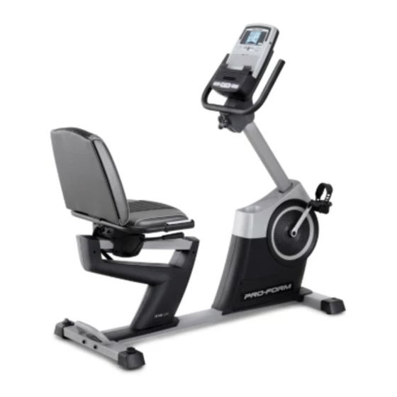
Page 4: Before You Begin
BEFORE YOU BEGIN Thank you for selecting the revolutionary PROFORM ® reading this manual, please see the front cover of this 310 CX exercise bike. Cycling is an effective exercise manual. To help us assist you, note the product model for increasing cardiovascular ... -
Page 5: Part Identification Chart
PART IDENTIFICATION CHART Use the drawings below to identify the small parts needed for assembly. The number in parentheses below each drawing is the key number of the part, from the PART LIST near the end of this manual. The number following the key number is the quantity needed for assembly. -
Page 6: Assembly
ASSEMBLY •• To hire an authorized service technician to •• In addition to the included tool(s), assembly assemble the exercise bike, call 1-800-445-2480. requires the following tools: one Phillips screwdriver •• Assembly requires two persons. one adjustable wrench •• Place all parts in a cleared area and remove the packing materials. - Page 7 3. Slide the Shield Cover (5) upward onto the Upright (4). Avoid pinching the wires Have a second person hold the Shield Cover (5) around the Upright (4) until you complete step 4. Tip: Avoid pinching the wires inside the Frame (1).
- Page 8 5. Make sure that the Wire Harness (89) and the Frame Pulse Wire (91) are in the location shown. Avoid pinching the wires Using a small plastic bag to keep your fingers clean, apply a coat of the included grease to an M6 x 70mm Bolt Set (67).
- Page 9 7. The Console (7) can use four D batteries (not included); alkaline batteries are recommended. Do not use old and new batteries together or Screw alkaline, standard, and rechargeable batter- ies together. IMPORTANT: If the Console has Battery Cover been exposed to cold temperatures, allow it to warm to room temperature before insert- ing batteries.
- Page 10 9. Identify the Right and Left Handlebar Covers (8, 9), which are marked with ““Right”” and ““Left”” stickers. Attach the Right and Left Handlebar Covers (8, 9) around the Handlebar (6) and the Upright (4) with four M4 x 16mm Screws (98). 10.
- Page 11 11. Attach the Backrest (13) to the Seat Carriage (11) with five M8 x 16mm Screws (60) and five M8 Split Washers (61). Tip: It may be helpful to adjust the seat dur- ing this step. See HOW TO ADJUST THE SEAT on page 13.
- Page 12 13. Plug the Pulse Bar Pulse Wire (92) into the Frame Pulse Receptacle (91) located in the Left Seat Shield (24). 14. Identify the Right Pedal (16), which is marked with an ““R.”” Using an adjustable wrench, firmly tighten the Right Pedal (16) clockwise into the Right Crank Arm (17).
-
Page 13: How To Use The Exercise Bike
HOW TO USE THE EXERCISE BIKE HOW TO ADJUST THE SEAT HOW TO ADJUST THE ANGLE OF THE HANDLEBAR The seat can be adjusted forward or backward to the position that is the most comfortable. To adjust the To adjust the angle of the handlebar, first loosen the seat, push downward on the seat handle, slide the seat knob a few turns. - Page 14 HOW TO MOVE THE EXERCISE BIKE HOW TO LEVEL THE EXERCISE BIKE To move the exercise If the exercise bike, hold the handle bike rocks slightly on the rear stabilizer on your floor and carefully lift it until during use, turn the exercise bike can one or both of the be moved on the front...
- Page 15 FEATURES OF THE CONSOLE CONSOLE DIAGRAM The console offers an array of features designed to make your workouts more effective and enjoyable. When you use the manual mode of the console, you can change the resistance of the pedals with the touch of a button.
- Page 16 HOW TO USE THE MANUAL MODE The lower right display——The 1. Begin pedaling or press any button on the lower right display console to turn on the console. can show your pedaling speed A moment after you begin pedaling or press a but- in revolutions ton, the display will turn on.
- Page 17 5. Measure your heart rate if desired. If the display does not show your heart rate, make sure that your hands are positioned as described. If there are sheets Be careful not to move your hands excessively or of plastic on the to squeeze the contacts tightly.
- Page 18 HOW TO USE A TIMED WORKOUT At the end of each segment of the workout, a series of tones will sound and the next segment of 1. Begin pedaling or press any button on the the profile will begin to flash. If a different resis- console to turn on the console.
- Page 19 HOW TO USE A WEIGHT LOSS WORKOUT At the end of each segment of the workout, a series of tones will sound and the next segment of 1. Begin pedaling or press any button on the the profile will begin to flash. If a different resis- console to turn on the console.
- Page 20 HOW TO USE AN IFIT WORKOUT Next, select the desired workout on the iFit card by pressing the increase and decrease buttons next to iFit cards are available separately. To purchase iFit the iFit slot. cards, go to www.iFit.com or see the front cover of this manual.
- Page 21 HOW TO CHANGE CONSOLE SETTINGS 3. Select a unit of measurement if desired. The console features a user mode that allows you to The console can show pedaling speed and dis- select a backlight option for the console and to view tance in either miles or kilometers.
-
Page 22: Maintenance And Troubleshooting
MAINTENANCE AND TROUBLESHOOTING Inspect and tighten all parts of the exercise bike regu- Repeat these actions until the console displays correct larly. Replace any worn parts immediately. feedback. When the reed switch is correctly adjusted, reattach the shield cover. To clean the exercise bike, use a damp cloth and a small amount of mild soap. -
Page 23: Exercise Guidelines
EXERCISE GUIDELINES Burning Fat——To burn fat effectively, you must exer- WARNING: cise at a low intensity level for a sustained period of Before beginning this time. During the first few minutes of exercise, your or any exercise program, consult your physi- body uses carbohydrate calories for energy. -
Page 24: Part List
PART LIST Model No. PFEX63911.0 R0112A Key No. Qty. Description Key No. Qty. Description Frame Idler Front Stabilizer Flywheel Rear Stabilizer Flywheel Axle Upright Motor Bracket Shield Cover Resistance Motor Handlebar Motor Disc Console Resistance Arm Right Handlebar Cover Adjustment Nut Left Handlebar Cover Resistance Bracket Seat Bracket... - Page 25 Key No. Qty. Description Key No. Qty. Description M6 x 20mm Flat Head Screw M6 Split Washer M4 x 13mm Flange Screw Power Adapter M4 x 13mm Bright Screw Seat Carriage Cap 1/4" x 14mm Screw Wire Clamp M6 x 16mm Screw Magnet M4 x 16mm Screw M4 x 16mm Phillips Screw...
-
Page 26: Exploded Drawing
EXPLODED DRAWING A Model No. PFEX63911.0 R0112A... - Page 27 EXPLODED DRAWING B Model No. PFEX63911.0 R0112A...
-
Page 28: Ordering Replacement Parts
ORDERING REPLACEMENT PARTS To order replacement parts, please see the front cover of this manual. To help us assist you, be prepared to provide the following information when contacting us: •• the model number and serial number of the product (see the front cover of this manual) ••...