Table of Contents
Advertisement
Advertisement
Table of Contents

Related Manuals for DURKOPP ADLER 281


Summary of Contents for DURKOPP ADLER 281
- Page 1 Operating Manual...
- Page 2 All rights reserved. Property of Dürkopp Adler AG and protected by copyright. Any reuse of these contents, including extracts, is prohibited without the written approval in advance of Dürkopp Adler AG. Copyright © Dürkopp Adler AG - 2013...
-
Page 3: Table Of Contents
Locking the sewing foot in place in the upper position ............37 5.13 Pushbutton on the machine arm......38 5.14 Operating the controller .......... 39 5.14.1 Control panel for the controller ....... 39 5.15 Sewing ..............42 Operating manual 281 Version 06.0 - 05/2013... - Page 4 Attaching the control panel ........62 7.13 Electrical connection..........63 7.13.1 Checking the mains voltage........63 7.13.2 Connecting the controller........63 7.13.3 Establishing equipotential bonding ......65 7.14 Sewing test ............. 66 Disposal..............67 Appendix ............... 68 Operating manual 281 Version 06.0 - 05/2013...
-
Page 5: About This Manual
Failure to observe the instructions in the manual • Improper use • Unauthorized modifications to the machine • The deployment of untrained personnel • Damage during transport • Using spare parts not approved Operating manual 281 Version 06.0 - 05/2013... -
Page 6: Symbols Used
Sequence Specifies the work to be performed before or after a setting. It is vital that this sequence is adhered to. Reference A reference is provided to another place in the text. Operating manual 281 Version 06.0 - 05/2013... -
Page 7: Safety Instructions
• Threading • Replacing the needle or other sewing tools • Leaving the workplace • Performing maintenance work and repairs Operating manual 281 Version 06.0 - 05/2013... - Page 8 Work on live components and equipment is prohibited. Exceptions are defined in DIN VDE 0105. Missing or faulty spare parts could impair safety and damage the machine. Therefore only use original spare parts from the manufacturer. Operating manual 281 Version 06.0 - 05/2013...
-
Page 9: Signal Words And Symbols Used In Safety Instructions
Attention: Damage possible. In the case of dangers to personnel, the following symbols indicate the type of hazard: General danger Danger due to electric shock Danger due to sharp objects Danger due to crushing Operating manual 281 Version 06.0 - 05/2013... - Page 10 Consequences in the event of noncompliance Measures for avoiding the danger This is what an environmental protection note looks like for a hazard that could result in environmental damage if not complied with. Operating manual 281 Version 06.0 - 05/2013...
-
Page 11: Performance Description
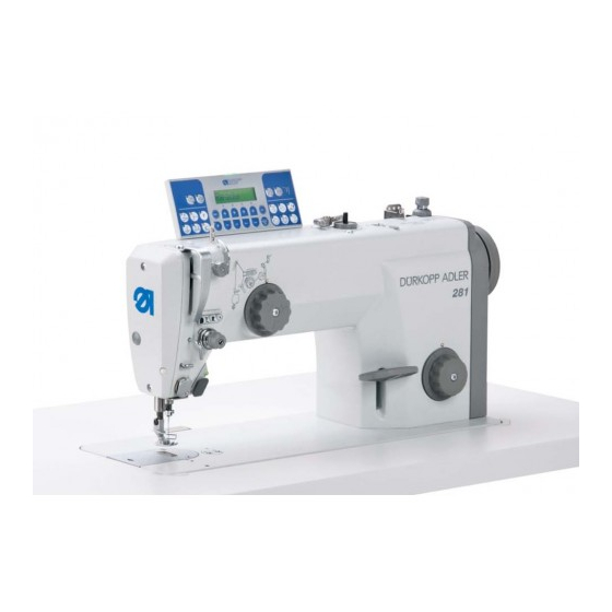
The machine complies with the European regulations specified in the declaration of conformity or in the installation declaration. 3.3 Intended use The Dürkopp Adler 281 is intended for sewing light to moderately heavy material. Intended yarn counts: • 30/3 NeB (cotton threads) •... -
Page 12: Technical Data
Rated voltage on delivery [V/Hz] 1x230 V 50/60 Hz Rated power [kVA] Length/width/height [mm] 540/430/215 Pack size incl. upper part, accessory pack, 785/694/300 and controller (length/width/height) [mm] Total weight (incl. packaging) [kg] 54.5 Operating manual 281 Version 06.0 - 05/2013... -
Page 13: Additional Equipment
Swivel arm for apparatus fastening N900 001941 Kit for moving binder for fine N900 003441 material Compensating hinged foot for edge 0204 001322 stitching, 0.8 mm to the right of the needle = standard equipment = optional additional equipment Operating manual 281 Version 06.0 - 05/2013... - Page 14 Apparatus to N514 with air, 8 mm 0281 590134 fold-over bridge, 1.2 mm passage (incl. WE8) Pneumatic connection package 0797 003031 = standard equipment = optional additional equipment Operating manual 281 Version 06.0 - 05/2013...
- Page 15 Frame incl. 1060x500 mm table MG53 plate with a pedal and drawer 400454 Frame with rollers incl. MG53 1250x900x700 mm table plate with 400554 a pedal and drawer = standard equipment = optional additional equipment Operating manual 281 Version 06.0 - 05/2013...
- Page 16 Performance description Operating manual 281 Version 06.0 - 05/2013...
-
Page 17: Device Description
(6) - Pushbutton on the machine arm (7) - Adjusting wheel for the sewing foot pressure (8) - Stitch adjustment lever (9) - Adjusting wheel for the stitch length (10) - Handwheel (11) - Bobbin Operating manual 281 Version 06.0 - 05/2013... - Page 18 Device description Operating manual 281 Version 06.0 - 05/2013...
-
Page 19: Operation
1. Press the main switch (1) down to position I. The indicator lamp (2) lights up. To switch off the power: 1. Press the main switch (1) up to position 0. The indicator lamp (2) goes out. Operating manual 281 Version 06.0 - 05/2013... -
Page 20: Inserting And Replacing The Needle
Faults caused by an incorrect hook clearance After inserting a thinner needle: • Missing stitches • Thread damage After inserting a thicker needle: • Damage to the hook tip • Damage to the needle Operating manual 281 Version 06.0 - 05/2013... - Page 21 3. Pull the needle out towards the bottom. 4. Insert the new needle. 5. Important: Align the needle so that the groove (4) faces the hook (3). 6. Tighten the fastening screw (2). Operating manual 281 Version 06.0 - 05/2013...
-
Page 22: Threading In The Needle Thread
2. Insert the thread from the rear to the front through a hole in the guide on the unwinding bracket (1). Important: The unwinding bracket (1) must be parallel to the thread stand (2). Operating manual 281 Version 06.0 - 05/2013... - Page 23 8. Pull the thread under the thread tensioning spring (5). 9. Guide the thread through, from the right to the left and under the hook (6). 10. Feed the thread from bottom to top through the thread regulator (4). Operating manual 281 Version 06.0 - 05/2013...
- Page 24 13. Insert the thread through the thread clamp (12). 14. Insert the thread through the thread guide on the needle bar (13). 15. Insert the thread from the left to the right through the needle eye (14). Operating manual 281 Version 06.0 - 05/2013...
-
Page 25: Inserting And Winding On The Hook Thread
6. Guide the thread clockwise around the gap on the adjusting knob (5). 7. Guide the thread from the right to the left through the hole on the second thread guide (4) to the bobbin. Operating manual 281 Version 06.0 - 05/2013... - Page 26 5.12 Locking the sewing foot in place in the upper position, page 37). Take the thread out of the thread lever and the bobbin capsule out of the hook if you wind on the hook thread without sewing the material in the process. Operating manual 281 Version 06.0 - 05/2013...
-
Page 27: Setting The Bobbin Filling Quantity
• Lower filling quantity: Pivot the metallic bobbin winder piece (2) towards the bobbin. • Larger filling quantity: Pivot the metallic bobbin winder piece (2) away from the bobbin. 3. Tighten the screw (1). Operating manual 281 Version 06.0 - 05/2013... -
Page 28: Replacing The Hook Thread Bobbin
6. Pull the hook thread approx. 5 cm out of the spool housing upper section (1). 7. Insert the spool housing upper section (1) with the full bobbin. 8. Close the spool housing flap (2). Operating manual 281 Version 06.0 - 05/2013... -
Page 29: Thread Tension
Figure 11: Thread interlacing ① ② ③ (1) - Identical needle thread and hook thread tension (2) - Hook thread tension higher than needle thread tension (3) - Needle thread tension higher than hook thread tension Operating manual 281 Version 06.0 - 05/2013... -
Page 30: Adjusting The Needle Thread Tension
Turn the adjusting wheel (2) clockwise. • To reduce the tension: Turn the adjusting wheel (2) counterclockwise. Opening the needle thread tensioner The main tensioner is automatically opened when the thread is cut. Operating manual 281 Version 06.0 - 05/2013... - Page 31 (1) is flush with bolt (3) in the center. To adjust the pre-tensioner: • Shorter initial thread: Turn the adjusting wheel (1) clockwise. • Longer initial thread: Turn the adjusting wheel (1) counterclockwise. Operating manual 281 Version 06.0 - 05/2013...
-
Page 32: Adjusting The Hook Thread Tension
(1) is full. • The total value of the hook thread tension should be applied 50% respectively through the braking spring (3) and the tensioning spring (2). Operating manual 281 Version 06.0 - 05/2013... - Page 33 8. Remove the hook thread in the direction of sewing at an angle of 45°. Fifty percent of the tension value should be achieved. 9. Then tighten the adjusting screw (3) up to the total tension value. Operating manual 281 Version 06.0 - 05/2013...
-
Page 34: Setting The Thread Regulator
The loop of the needle thread (2) slides at low tension over the thickest point of the hook (1). Figure 16: Setting the thread regulator: Correct needle thread quantity ① ② (1) - Hook (2) - Needle thread loop Operating manual 281 Version 06.0 - 05/2013... - Page 35 2. Move the thread regulator (1): • Lower thread quantity: Slide the thread regulator (1) to the right • Larger thread quantity: Slide the thread regulator (1) to the left 3. Tighten the fastening screws (2). Operating manual 281 Version 06.0 - 05/2013...
-
Page 36: Adjusting The Stitch Length
1. Slowly push the stitch adjustment lever (1) down as far as it will go. The stitch length is reduced. Backwards sewing starts after the zero point. In the lower end position, the machine sews backwards with the set stitch length. Operating manual 281 Version 06.0 - 05/2013... -
Page 37: Setting The Sewing Foot Pressure
Setting the sewing foot pressure: 1. Turn the adjusting wheel (2). • To increase the sewing foot pressure: Turn the adjusting wheel (2) clockwise. • To reduce the sewing foot pressure: Turn the adjusting wheel (2) counterclockwise. Operating manual 281 Version 06.0 - 05/2013... -
Page 38: Lifting The Sewing Foot
Risk of crushing when lowering the sewing foot. Do not put your hands underneath the lifted sewing foot. Lowering the sewing foot 1. Release the knee lever (1). The sewing foot is lowered. Operating manual 281 Version 06.0 - 05/2013... -
Page 39: Locking The Sewing Foot In Place In The Upper Position
The sewing foot is lowered. The locking mechanism is removed. 1. Lift the sewing foot using the knee lever ( page 36). The sewing foot is lowered. The locking mechanism is removed. The lever swings back to position (1). Operating manual 281 Version 06.0 - 05/2013... -
Page 40: Pushbutton On The Machine Arm
The buttons can be used to perform the following functions: • Button (2): Switching the sewing lamp on/off • Button (3): Activate / deactivate the bartack suppression • Button (4): Half stitch, positioning the needle up/down • Button (5): Manual bartack Operating manual 281 Version 06.0 - 05/2013... -
Page 41: Operating The Controller
⑯ ⑮ ⑭ Switch on/off function 1. Press the appropriate key. The LED on the key indicates the status. Important: The functions only work on the machine if the appropriate equipment is available. Operating manual 281 Version 06.0 - 05/2013... - Page 42 LED off LED on Seam program II LED off LED on Seam program I LED off LED on Sewing foot lifting after sewing Sewing foot down LED off stop Sewing foot up LED on Operating manual 281 Version 06.0 - 05/2013...
- Page 43 Needle position after sewing Needle down LED off stop Needle up LED on Freely programmable key Escape key, abort Programming key Ready to be LED on programmed Increase value Decrease value Confirmation Reset Bobbin supply Operating manual 281 Version 06.0 - 05/2013...
-
Page 44: Sewing
2. Push the material to be sewn into the initial position. Sewing: 1. Press the foot pedal forwards in pedal position +1: The machine sews. The sewing speed increases the further forward the pedal is pressed. Operating manual 281 Version 06.0 - 05/2013... - Page 45 The needle is up. The sewing foot is down. 2. Press the knee lever ( Section 5.11 Lifting the sewing foot, page 36). The sewing foot is lifted. 3. Remove the sewn material. Operating manual 281 Version 06.0 - 05/2013...
- Page 46 Operation Operating manual 281 Version 06.0 - 05/2013...
-
Page 47: Maintenance
Flying dirt particles can get in the eyes, causing injury. Hold the compressed-air pistol in such a way that no particles fly near persons. Take care that no particles fly into the oil pan. Operating manual 281 Version 06.0 - 05/2013... - Page 48 2. Remove any sewing dust and thread remains using a compressed-air pistol or a brush. ATTENTION Possible damage to the paintwork from solvent-based cleaners. Solvent-based cleaners damage the paintwork of the machine. Only use solvent-free substances for wiping the machine. Operating manual 281 Version 06.0 - 05/2013...
-
Page 49: Lubrication
Make sure that there is always sufficient oil in the respective reservoir. ATTENTION Machine damage possible due to incorrect oil. An incorrect oil type can cause damage to the machine. Only use oil that complies with the data in the operating manual. Operating manual 281 Version 06.0 - 05/2013... -
Page 50: Hook Lubrication
Important: To do this, the knee lever must be removed. ( Section 7.11 Fitting the knee lever, page 61) 3. Check the quantity of oil in the reservoir (2). 4. Pour in oil through the refill hole (1) as required. Operating manual 281 Version 06.0 - 05/2013... -
Page 51: Gear Lubrication
3. Check the oil level in the inspection window (2). 4. Unscrew the screw plug (1) together with the sealing ring. 5. Top up the gear oil to the middle of the inspection window (2). Operating manual 281 Version 06.0 - 05/2013... -
Page 52: Repairs
Contacts for repair in the event of damage to the machine: Dürkopp Adler AG Potsdamer Str. 190 33719 Bielefeld Ph. +49 (0) 180 5 383 756 Fax +49 (0) 521 925 2594 Email: service@duerkopp-adler.com Internet: www.duerkopp-adler.com Operating manual 281 Version 06.0 - 05/2013... -
Page 53: Set-Up
(6) - Pedal (2) - Upper part of machine (7) - Rod (3) - Table plate (8) - Oil pan (4) - Drawer (9) - Controller (5) - Frame (10) - Thread stand Operating manual 281 Version 06.0 - 05/2013... -
Page 54: Removing The Transport Securing Devices
All transport securing devices must be removed prior to set-up. 1. Remove the lashing straps and wooden blocks from the machine upper section, the table, and the frame. 2. Remove the supporting wedges between the machine arm and needle plate. Operating manual 281 Version 06.0 - 05/2013... -
Page 55: Fitting The Frame Components
1. Screw the cross bars (3) onto the frame bars (2). 2. Screw the cross strut (5) onto the foot struts (4). 3. Screw the head sections (1) onto the frame bars (2). Operating manual 281 Version 06.0 - 05/2013... -
Page 56: Completing The Table Plate
7. Fasten the thread stand (1) with nut and washer. 8. Screw the thread reel holder and the unwinding bracket onto the thread stand (1) in such a way that they are exactly parallel above each other. Operating manual 281 Version 06.0 - 05/2013... -
Page 57: Fastening The Table Plate To The Frame
(2) such that the table plate is flush with the rear edge of the foot struts (3) at the rear. This increases stability when folding over the upper part of the machine. Operating manual 281 Version 06.0 - 05/2013... -
Page 58: Setting The Working Height
2. Set the table plate to the desired height. Important: Pull out or push in the table plate evenly at both sides to prevent it from jamming. 3. Tighten the screws (1) on the head sections. Operating manual 281 Version 06.0 - 05/2013... -
Page 59: Controller
1. Screw the controller (3) onto the four screw holders (2) under the table plate. 2. Clamp the power cable for the controller into the strain relief mechanism (1). 3. Screw the strain relief (1) under the table plate. Operating manual 281 Version 06.0 - 05/2013... -
Page 60: Fit The Pedal And Setpoint Device
5. Hang the pedal rod (4) with the ball socket on the setpoint device (2) and attach to the pedal (5). 6. Pull the pedal rod (4) to the correct length: Correct setting: 10° inclination with pedal (5) released 7. Tighten the screw (3). Operating manual 281 Version 06.0 - 05/2013... -
Page 61: Inserting The Machine Upper Section
2. Fit the machine upper section from above at an angle of 45°. 3. Insert the upper hinge parts (1) into the rubber inlays (2). 4. Fold the machine upper section down and insert it in the recess. Operating manual 281 Version 06.0 - 05/2013... -
Page 62: Attaching The Upper Section Retaining Strap
Figure 38: Attaching the oil can ② ① (1) - Oil pan (2) - Oil can 1. Tilt the machine upper section backwards. 2. Attach the oil can (2) into the oil pan (1) from below. Operating manual 281 Version 06.0 - 05/2013... -
Page 63: Fitting The Knee Lever
If, in a fully installed machine, the upper section is going to be tilted backwards, e.g. for maintenance work, then the knee lever has to be removed previously in order to do this. Operating manual 281 Version 06.0 - 05/2013... -
Page 64: Attaching The Control Panel
10. Fit the handwheel cover (7). 11. Tighten all three handwheel screws (5). 12. Tighten all four handwheel cover screws (6). Operating manual 281 Version 06.0 - 05/2013... -
Page 65: Electrical Connection
To do this, read the Operating manual for the DAC BASIC control system. The operating manual is provided in the controller accessory pack. The operating manual for the controller is also available in the download area at www.duerkopp-adler.com. Operating manual 281 Version 06.0 - 05/2013... - Page 66 (9) - Connection for control panel Connecting the components to the controller 1. Insert the plugs for the individual components into the respective connecting sockets on the rear side of the controller. Operating manual 281 Version 06.0 - 05/2013...
-
Page 67: Establishing Equipotential Bonding
3. Fasten grounding wire (1) for the machine upper section, together with the grounding wire (3) for the frame, to the screw (2) on the rear side of the controller. 4. Raise the machine upper section. Operating manual 281 Version 06.0 - 05/2013... -
Page 68: Sewing Test
8. Adjust the sewing foot pressure to the material to be sewn. 9. Adjust the stitch length. 10. Start the sewing test at low speed. 11. Increase the sewing speed continuously until the working speed is reached. Operating manual 281 Version 06.0 - 05/2013... -
Page 69: Disposal
When disposing of the machine, be aware that it consists of a range of different materials (e. g. steel, plastic, electronic components, oily parts). Observe the respectively applicable national regulations for each type of material. Operating manual 281 Version 06.0 - 05/2013... - Page 70 Disposal Operating manual 281 Version 06.0 - 05/2013...
-
Page 71: Appendix
Appendix 9 Appendix Dimensions for manufacturing a table plate Operating manual 281 Version 06.0 - 05/2013... - Page 72 Appendix Operating manual 281 Version 06.0 - 05/2013...
- Page 74 DÜRKOPP ADLER AG Potsdamer Str. 190 33719 Bielefeld Germany Phone +49 (0) 521 925 00 E-Mail: service@duerkopp-adler.com www.duerkopp-adler.com...