dbx Zone Pro 640 User Manual
Digital zone processor
Hide thumbs
Also See for Zone Pro 640:
- Manual (2 pages) ,
- Manual (2 pages) ,
- Installation manual (24 pages)
Table of Contents
Advertisement
Advertisement
Table of Contents

Related Manuals for dbx Zone Pro 640


Summary of Contents for dbx Zone Pro 640
- Page 1 ® 640/641 User Manual...
-
Page 2: Important Safety Instructions
IMPORTANT SAFETY INSTRUCTIONS WARNING FOR YOUR PROTECTION C A U T I O N READ THE FOLLOWING: R I S K O F E L E C T R I C S H O C K D O N O T O P E N KEEP THESE INSTRUCTIONS A T T E N T I O N : R I S Q U E D E C H O C E L E C T R I Q U E - N E P A S O U V R I R... -
Page 3: Declaration Of Conformity
89/336/EEC as amended by Directive 93/68/EEC. Vice-President of Engineering 8760 S. Sandy Parkway Sandy, Utah 84070, USA Date: February 6, 2004 European Contact: Your local dbx Sales and Service Office or Harman Music Group 8760 South Sandy Parkway Sandy, Utah 84070 USA Ph: (801) 566-8800... -
Page 4: Table Of Contents
640/641 Table of Contents Introduction 4.10 Auto Warmth..........28 4.11 Band Pass Filter/Crossover ......29 0.1 Defining the Zone Pro 640/641 ......ii 4.12 Output PEQ ..........30 0.2 Service Contact Info........iii 4.13 Output Dynamics .........30 0.3 Warranty............iv 4.14 Delay .............32 Section 1 - Getting Started 3.15 Output Polarity ..........32... - Page 5 640/641 INTRODUCTION INTRO CUSTOMER SERVICE INFO Defining the ZonePro WARRANTY INFO ®...
- Page 6 ZonePro 640 and 641. 0.1 - Defining the ZonePro System The dbx ZonePro units are the most effective way to manage all aspects of BGM processing and signal routing. The ZonePro essentially becomes the only device that you will need between the mixer and the power amps.
-
Page 7: Service Contact Info
In addition to the amazing menu of processing available, the ZonePro units also afford you the luxury of utilizing dbx Zone-Controller series wall-mounted control panels that will allow you to remotely control various parameters of the unit. The ZC-1 and ZC-6 offer remote program- mable Volume control to any installation using the ZonePro units. -
Page 8: Warranty
In no event shall dbx or its dealers be liable for special or con- sequential damages or from any delay in the performance of this warranty due to causes beyond their control. - Page 9 Section 1 ™ ZonePro Getting Started ®...
-
Page 10: Section 1 - Getting Started
™ ZonePro Section 1 Getting Started 1.1 - Rear Panel (640 and 641) 7 8 9 1. IEC Power Cord Receptacle The ZonePro 640/641 comes with a power supply that will accept voltages ranging from 100V- 120V at frequencies from 50Hz-60Hz. An IEC cord is included. EU version accepts 220V-240V at frequencies from 50Hz-60Hz. -
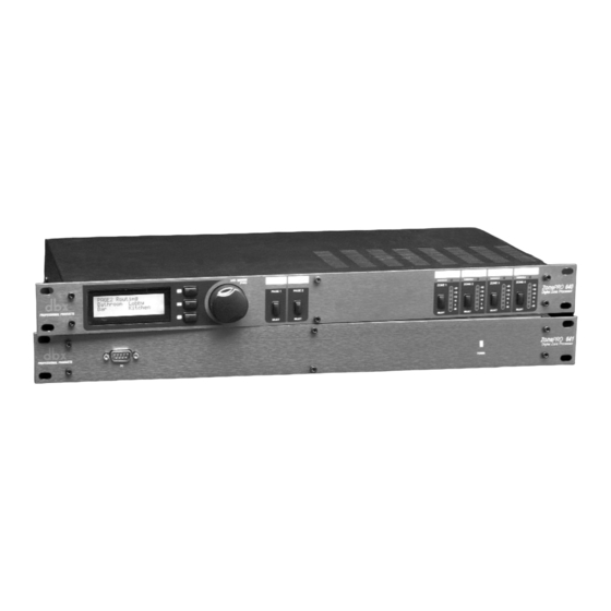
Page 11: 640)Front Panel
™ ZonePro Section 1 Getting Started 1.2 - Front Panel (640) 5 6 7 1. LCD Display The backlit LCD display of the ZonePro 640 provides the end-user with all the necessary con- trols including source selection, page steering, zone volume and mute. 2. -
Page 12: Connections
1024 x 768 pixels or higher Installation • Install the ZonePro GUI software from either the dbx website at www.dbxpro.com or from the included CD ROM onto your computer. • Once the software setup is downloaded, double click on the file named: ZonePro setup. - Page 13 Section 2 ™ ZonePro SOFTWARE OPERATION ®...
-
Page 14: Section 2 - Software Operation
™ ZonePro Section 2 Software Operation For your convenience, all the configuration and editing features of the ZonePro™ 640 and 641 are performed via the included Zone Pro GUI. This section has been created to act as a tuto- rial for performing various editing aspects of the unit. 2. -
Page 15: Online/Offline
™ ZonePro Section 2 Software Operation 2. 4 - Online/Offline The ZonePro Designer GUI provides a mechanism for creating scenes and device files while not physically connected to a ZonePro unit. To work off-line, open the GUI, select DEVICE then select ADD. At this point you will be prompted to choose a 640 or 641. Once the unit has been inserted into GUI you can proceed to configure, edit, create scenes, and save ZonePro device files. -
Page 16: Saving And Recalling Scenes
™ ZonePro Section 2 Software Operation 2. 7 - Saving and Recalling Scenes As previously stated, scenes include parameter data and zone controller assignment. Multiple scenes can be saved and recalled by either clicking on the Scene tab of the Menu bar or by using the Store Scene and Recall Scene buttons. - Page 17 Section 3 ™ ZonePro Setup SYSTEM SETUP ®...
-
Page 18: Section 3 - System Setup
™ ZonePro Section 3 System Setup 3.1 - Overview The System Setup section of the ZonePro manual will provide the user with detailed instruc- tion for Configuration of the ZonePro unit and any Zone Controllers that may be used with it. The following sub-sections will provide you with detailed information regarding the various setup functions. - Page 19 ™ ZonePro Section 3 System Setup 3.2.1 Input Setup • This page is the Input Setup Page page and allows naming of inputs, input configuration (mono or stereo), and selection of the two mic/line DSP modules. Once you have named your inputs and selected insert modules, click on the Next Page button and the display will appear as follows: 3.2.2 Output Setup...
- Page 20 ™ ZonePro Section 3 System Setup 3.2.3 ZC Panel Configuration The ZC Panel Configuration Page allows setup of wall-mounted Zone Controllers to be used with the ZonePro unit. ID #s - The ID numbers on the left side of the window correspond to the identification num- ber set using the DIP switches on the individual zone controllers.
-
Page 21: System Setup
™ ZonePro Section 3 System Setup controller, then select the desired zones with each of the 16 switch positions. Like a ZC-3, the ZC-7 only has four positions so it will only support up to four zones or groups of zones, but it does have momentary switches that can be used in a push to call fashion, where each switch must be pushed and held to route the page to that zone or group of zones. -
Page 22: Scene Wizard
™ ZonePro Section 3 System Setup 3.2.5 Front Panel Setup • The Front Panel Setup Page allows selection of which controls will be available to the end- user of the 640 unit. If Zone Controllers are being used for page steering, source, or vol- ume control of an output zone these parameters will not be available from the front panel. -
Page 23: Schedule Wizard
™ ZonePro Section 3 System Setup 3.4 - Schedule Wizard The Schedule Wizard provides for pre-determined scene changes corresponding to the time of day and/or day of week. For example installations such as restaurants often require volume increases during peak hours of operation. This sub-section will walk you through setting up the Schedule Wizard. - Page 24 ™ ZonePro Section 3 System Setup ® ZonePro ™ User Manual...
-
Page 25: Section 4 - Detailed Parameters
Section 4 ™ ZonePro Detailed Parameters DETAILED PARAMETERS ®... -
Page 26: Input
™ ZonePro Section 4 Detailed Parameters The following section will provide you with a module block representation for each effect, as well as descriptions and explanations of all parameters within the ZonePro. 4.1 - Input The signal routing begins at the INPUT block of the ZonePro™. Gain Level -Inf to 20dB Adjusts the input level. -
Page 27: Automatic Gain Control (Agc)
™ ZonePro Section 4 Detailed Parameters Flat /Restore These buttons either flatten (Flat) or restore (Restore) all bands to their original settings. Band (1-4) Frequency 20Hz to 20kHz (Low Shelf) Selects the frequency of the EQ. Q (1-4) 0.105 to 16.0 Selects the Q or the Bell parametric EQ. -
Page 28: Notch Filters
™ ZonePro Section 4 Detailed Parameters Target -20 to 20 dB The Target parameter defines where you would like the average level of the AGC output to be. If the average level of the signal rises above the Target the gain will be reduced. For signals with an average level below the Target the gain will be increased. -
Page 29: Compressor
™ ZonePro Section 4 Detailed Parameters Notch On/Off Turns the notch filters on and off. Frequency (1 to 6) 20 to 20K Selects the desired notch filter frequency of the selected notch filter. Q 16 to 128 Selects the Q of the selected notch filter. Level -36 to 6 dB Sets the level of the selected notch filter. - Page 30 ™ ZonePro Section 4 Detailed Parameters Compressor On/Off Turns the Compressor module on and off. OverEasy Off to 10 OverEasy is a soft-knee smoothing function that occurs about the compression threshold. OverEasy off is considered hard knee; the higher the OverEasy the greater the smoothing. Threshold -40 to +20dBu Threshold is the signal level at which the unit starts to compress the signal.
-
Page 31: Noise Gate
™ ZonePro Section 4 Detailed Parameters Auto On/Off When Auto Mode is on, the ZonePro™ automatically sets the Attack, Hold, and Release times for the signal. The auto mode constantly adjusts these parameters in real time for optimum per- formance from the unit. You will find that for most applications, not only is using the auto mode faster and easier but by letting the unit constantly tweak these parameters for you will result in a better end result. -
Page 32: De-Esser
™ ZonePro Section 4 Detailed Parameters Threshold -50 to 20 dBu The threshold is the level at which the gate opens. Anything above the threshold passes, while signal that is lower than the threshold is attenuated. Beware, setting the threshold to high can cut off the tail end of signals as they fade out (the sustain of a guitar note, a held piano chord, a reverb tail, etc.). -
Page 33: Advanced Feedback Suppression (Afs)
™ ZonePro Section 4 Detailed Parameters Freq 800 Hz to 8.00 kHz This is the center frequency the De-Esser uses when in Band Pass mode or the corner frequency used when in High Pass mode. Amount 0 to 100% This controls the amount of De-Essing. The amount control is very much like a combination threshold / ratio control. - Page 34 ™ ZonePro Section 4 Detailed Parameters Mode - Live or Fixed When the mode is Fixed, the algorithm updates only the fixed filters. When the mode is Live, the algorithm updates only the live filters. In FIXED mode, the filters are stored with the pro- gram at that frequency until cleared by the user.
-
Page 35: Router
™ ZonePro Section 4 Detailed Parameters 4.9 - Router The Router module is the heart of the ZonePro device and allows for a primary source, a pri- ority override sources and a paging source, where the paging source has the highest priority. Both priority override and page have duckers that allow them to duck the previous sources. -
Page 36: Auto Warmth
™ ZonePro Section 4 Detailed Parameters The Page Ducker attenuates both the primary source and the Priority source if present. A Page source Gate can be added using the Mic/Line Insert 1 or 2. Threshold -40 to +20dBu Threshold is the level from the priority or page source at which the Ducker will attenuate the Router source. -
Page 37: Band Pass Filter/Crossover
™ ZonePro Section 4 Detailed Parameters Auto Warmth On/Off This parameter is used to turn the Autowarmth module on and off. Threshold -40 to +20dBu The threshold sets the level where AutoWarmth® begins to work. Signals below the threshold are processed to increase the Bass response in proportion to the overall volume of the signal. Above the threshold there is no processing. -
Page 38: Output Peq
™ ZonePro Section 4 Detailed Parameters 4.12 - Output Parametric EQ The ZonePro units offer parametric EQ on all inputs. A 4-Band PEQ is available on the Mic/Line inputs while a 2-Band PEQ is available on the RCA line inputs. EQ On/Off Turns the PEQ on and off. - Page 39 ™ ZonePro Section 4 Detailed Parameters Limiter On/Off Turns the Limiter module on and off. OverEasy (O) Off to 10 OverEasy is a soft-knee smoothing function that occurs about the limiting threshold. OverEasy off is considered hard knee; the higher the OverEasy, the greater the smoothing. Threshold -40 to +20dBu Threshold is the signal level at which the unit starts to limit the signal.
-
Page 40: Delay
™ ZonePro Section 4 Detailed Parameters PeakstopPlus ® On/Off The first stage of PeakStopPlus is the Instantaneous Transient Clamp™ which clamps the signal with a soft logarithmic clamp function. This logarithmic function ensures that the signal will not exceed the level set by the PeakStopPlus OVERSHOOT control by more than the overshoot amount, and that it will not introduce harsh artifacts. -
Page 41: Section 5- Application Guide
Section 5 ™ ZonePro APPLICATION GUIDE ®... -
Page 42: Retail Establishment
ZonePro ™ SECTION 5 Application Guide 5.1 - Retail Install ® ZonePro™ User Manual... - Page 43 ™ ZonePro SECTION 5 Application Guide Retail Application Notes 1. The configuration is setup from the Wizard function and is used to select the main inputs to each zone except the sales floor where the ZCs are selected as the source and level. 2.
-
Page 44: Restaurant Install
™ ZonePro SECTION 5 Application Guide 5.2 - Restaurant/Bar Install ® ZonePro™ User Manual... - Page 45 ™ ZonePro SECTION 5 Application Guide Notes - Restaurant/Bar Application 1. The ZonePro 640 is located in the manager’s office and provides source selection for the wait- ing area. 2. Both the restaurant and the bar area have ZC controllers. The bar is using them for source selection and volume control, the ZC-1 in the restaurant is used for volume control, and the ZC-3 is used for scene changes.
-
Page 46: Health Club
™ ZonePro Section 5 Application Guide 5.3 - Health Club Install ® ZonePro™ User Manual... - Page 47 ™ ZonePro Section 5 Application Guide Notes - Health Club Application 1. The ZonePro 640 units are located near the front desk area. 2. ZCs in the weight room and the aerobics room allow source selection and volume control. 3. The aerobics instructor’s microphone is routed only to the aerobics area as the Priority source and is simply mixed in as the priority source rather than Ducking the primary source.
-
Page 48: Night Club
™ ZonePro Section 5 Application Guide 5.3 - Night Club Install ® ZonePro™ User Manual... - Page 49 ZonePro ™ Section 5 Application Guide Notes - Nightclub Application 1. The ZonePro 640 units are located in the manager’s office. 2. The ZCs in the nightclub are situated near the bar and allow source selection and volume control. 3. The feed from the nightclub allows the restaurant to receive the signal from the nightclub allowing it to be sent to the entire restaurant.
- Page 51 Appendix ™ ZonePro ®...
-
Page 52: Appendix
™ ZonePro Appendix A.1 - Factory Reset/Flash Update In the event that a reset is required, the ZonePro™ offers you the option of performing a “Soft” or “Hard” reset. The Soft Reset resets all operating parameters except user programs. The Hard Reset Procedure will reset all programmable information back to the factory defaults. -
Page 53: Specifications
120 Ω balanced, 60Ω unbalanced Max Output Level: +20dBu A/D Performance: Type: dbx Type IV™ conversion system Dynamic Range line: >113 dB A-weighted, >110 dB unweighted Type IV dynamic range: >119 dB, A-weighted, 22kHz BW >117 dB, unweighted, 22kHz BW... -
Page 54: Block Diagram
™ ZonePro Appendix A.3 - Block Diagram ® ZonePro™ User Manual... -
Page 55: Link I/O
™ ZonePro Appendix A.4 - Link Input/Output CAUTION: These servicing instructions are for use by qualified service personnel only. To reduce the risk of electric shock, do not perform any servicing other than that contained in the operating instructions unless you are qualified to do so. -
Page 56: Zone Controller Wiring And Install
™ ZonePro Appendix A.5 - Zone Controller Wiring and Install Zone Controller Wiring The Zone Controllers, (ZC-1, ZC-2, ZC-3, ZC-4) can be wired serially or in parallel. To wire in series each Zone Controller must have an identification or zone number chosen using the DIP switches on the side of the controller (see diagram A). - Page 57 ™ ZonePro Appendix Diagram A Diagram B ID # 1 ID # 4 80- 1342-A 80- 1342-A Diagram C ® ZonePro™ User Manual...
- Page 58 ™ ZonePro Appendix Cable Specification: Cat 5 Cable - 4-Twisted Pairs of 24 AWG wire RJ-45 RJ-45 (8-Position) (8-Position) White/Orange -VREF Orange -Zone 1 White/Green -Zone 2 Green -Zone 3 White/Blue -Zone 4 Blue -Zone 5 White/Brown -Zone 6 Brown -GND Diagram A Diagram B...
- Page 59 ® 8760 South Sandy Parkway • Sandy, Utah 84070 Phone: (801) 568-7660 • Fax (801) 568-7662 Int’l Fax: (801) 568-7583 Questions or comments? E-mail us at: customer@dbxpro.com or visit our World Wide Web home page at: www.dbxpro.com A Harman International Company 18-0282-A...