dbx Zone Pro 1260 User Manual
Digital zone processor
Hide thumbs
Also See for Zone Pro 1260:
- User manual (73 pages) ,
- Manual (2 pages) ,
- Installation manual (24 pages)
Table of Contents
Advertisement
Advertisement
Table of Contents

Related Manuals for dbx Zone Pro 1260


Summary of Contents for dbx Zone Pro 1260
- Page 1 1 2 6 0 / 1 2 6 1 User Manual...
-
Page 2: Important Safety Instructions
IMPORTANT SAFETY INSTRUCTIONS WARNING FOR YOUR PROTECTION READ THESE INSTRUCTIONS: KEEP THESE INSTRUCTIONS HEED ALL WARNINGS FOLLOW ALL INSTRUCTIONS The symbols shown above are internationally accepted symbols that warn of potential hazards with electrical DO NOT USE THIS APPARATUS NEAR WATER products. -
Page 3: Declaration Of Conformity
Vice-President of Engineering – Pro 8760 S. Sandy Parkway Sandy, Utah 84070, USA Date:August 23, 2004 European Contact: Your local dbx Sales and Service Office or Harman Music Group 8760 South Sandy Parkway Sandy, Utah 84070, USA Ph: (801) 566-8800... -
Page 4: Table Of Contents
™ ZonePRO Introduction Introduction 4.12 Output Dynamics .........32 4.13 Delay .............33 0.1 ZonePro Features ..........ii 4.14 Output Polarity ..........33 0.2 Service Contact Info ........iii 0.3 Warranty............iv Section 5- Application Guide Section 1 - Getting Started 5.1 Restaurant Install ..........36 5.2 Health Club.............38 1.1 Rear Panel Connections ........2 5.3 Night Club............40 1.2 (1260)Front Panel ..........3... - Page 5 ™ ZonePRO INTRODUCTION INTRO CUSTOMER SERVICE INFO Defining the ZonePRO WARRANTY INFO...
-
Page 6: Introduction
™ ZonePRO Introduction Congratulations on your purchase of the dbx ZonePRO 1260 and/or 1261! The ZonePRO prod- ® INTRODUCTION ucts are based on the same unparalleled design philosophy that made the DriveRack family famous. This philosophy, “To provide everything you need between the sources and the ampli- fiers,”... -
Page 7: Service Contact Info
In addition to the processing available, the ZonePRO units provide intuitive wall-panel control from the dbx Zone Controller (ZC) series. The ZC-1 and ZC-6 offer remote programmable Volume control to any installation using the ZonePRO units. The ZC-2 provides programmable Volume and Mute control. -
Page 8: Warranty
In no event shall dbx or its dealers be liable for special or consequential damages or from any delay in the performance of this warranty due to caus- es beyond their control. -
Page 9: Section 1 - Getting Started
Section 1 ™ ZonePRO Getting Started... -
Page 10: Rear Panel Connections
™ ZonePRO Section 1 Getting Started 1.1 - Rear Panel (1260 and 1261) 1. IEC Power Cord Receptacle The ZonePRO 1260/1261 comes with a power supply that will accept voltages ranging from 100V-240V at frequencies from 50Hz-60Hz. An IEC cord is included. 2. -
Page 11: 1260)Front Panel
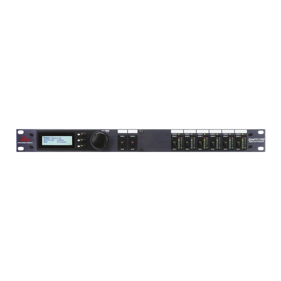
™ ZonePRO Section 1 Getting Started 1.2 - Front Panel (1260) 1. LCD Display The backlit LCD display of the ZonePRO 1260 provides the end-user with all the necessary con- trols including source selection, page steering, zone volume and mute. 2. -
Page 12: Zonepro Designer Gui
Recommended screen resolution: 1024 x 768 pixels or higher Installation • Install the ZonePRO GUI software from either the dbx website at www.dbxpro.com or from the included CD ROM onto your computer. • Once the software setup is downloaded, double click on the file named: ZonePRO setup. - Page 13 Section 2 ™ ZonePRO SOFTWARE OVERVIEW...
-
Page 14: Section 2 - Software Overview
™ ZonePRO Section 2 Software Overview For your convenience, all the configuration and editing features of the ZonePRO™ 1260 and 1261 are performed via the included ZonePRO Designer GUI. This section has been created to act as a tutorial for performing various editing aspects of the unit. 2. - Page 15 ™ ZonePRO Section 2 Software Overview unit; double clicking on the unit also takes you to the Unit view. When off - l i n e , You can delete the unit by selecting D e l e t e f rom the Device Menu. Selecting P ro p e rt i e s f rom the Device menu allows you to view and edit some of the device properties like the device's name, its MAC address, Its Node address, and its peak output level.
-
Page 16: Unit View Functions
™ ZonePRO Section 2 Software Overview 2. 4 - Unit View Functions The Unit View provides access to the signal routing configuration, Zone Controller assignment, and processing parameters. 2.4.1 File Menu The File Menu selection allows saving of the existing ZonePRO device file (.zpd) as well as recalling of other files. - Page 17 ™ ZonePRO Section 2 Software Overview 2.4.4 Wizard Menu The Wizard Menu provides setup functions for the unit configuration, scene changes that might involve routing or ZC assignment changes, and automated scene changes via the real time clock schedule. Configuration of the ZonePRO device is done from the Configuration Wizard and allows setup of the inputs and outputs along with selection of their processing modules, zone controller setup, signal routing, and front panel setup.
-
Page 18: Module View Functions
™ ZonePRO Section 2 Software Overview 2. 5 - Module View Functions Double clicking on a processing module provides access to those parameters. All modules except for the input Gain module and the output Polarity have ON/OFF buttons allowing the processing of that module to be bypassed. Any changes made to the processing happen in real time as long as the ON/OFF button is turned on (indicated by the button turn- ing red). - Page 19 Section 3 ™ ZonePRO Setup S O F T WA R E OPERATION...
-
Page 20: Section 3 - Software Operation
™ ZonePRO Section 3 Software Operation 3.1 - Overview The Software operation section of the manual will provide in-depth step by step instructions for setting up a ZonePro 1260 or 1261 and any Zone Controllers that may be used with it. The following subsections will provide you with detailed information regarding the various set up functions. - Page 21 ™ ZonePRO Section 3 Software Operation 3.3.1 Source Configuration This page is the Input Setup Page, and allows naming of inputs, input configuration (mono or stereo), and selection of the two mic/line DSP modules. Once you have named your inputs and selected insert modules, click on the Next Page button and the display will appear as fol- lows: 3.3.2 Zone Configuration...
- Page 22 ™ ZonePRO Section 3 Software Operation 3.3.3 ZC Panel Configuration The ZC Panel Configuration Page allows setup of wall-mounted Zone Controllers to be used with the ZonePRO unit. ID #s - The ID numbers on the left side of the window correspond to the identification num- ber set using the DIP switches on the individual zone controllers.
- Page 23 ™ ZonePRO Section 3 Software Operation Edit - Source Selection - A ZC-3, ZC-4, ZC-8, or ZC-9 can be used to provide source selection. Select the desired ZC type and make sure it has the correct ID number. For a ZC-3, ZC-8, or ZC-9 for each switch position, select the cor- responding source.
-
Page 24: Parameter Editing
™ ZonePRO Section 3 Software Operation 3.3.6 Front Panel Configuration The Front Panel Setup Page allows selection of which controls will be available to the end-user of the ZonePRO unit. If Zone Controllers are being used for page steering, source, or volume c o n t ro l of an output zone these parameters will not be available from the front panel. -
Page 25: Storing Scenes
™ ZonePRO Section 3 System Setup 3.5 - Storing Scenes After editing parameters the scene needs to be stored. You can store the scene by using the Scene Store button at the base of the device view, or use the Scene Wizard Menu also found in the device view. -
Page 26: Schedule Wizard
™ ZonePRO Section 3 System Setup 3.7 - Schedule Wizard The Schedule Wizard provides for pre-determined scene changes corresponding to the time of day and/or day of week. For example installations such as restaurants often require volume increases during peak hours of operation. This sub-section will walk you through setting up the Schedule Wizard. -
Page 27: Section 4 - Detailed Parameters
Section 4 ™ ZonePRO Detailed Parameters DETAILED PARAMETERS... -
Page 28: Input
™ ZonePRO Section 4 Detailed Parameters The following section will provide you with a module block representation for each effect, as well as descriptions and explanations of all parameters within the ZonePRO. 4.1 - Input The signal routing begins at the INPUT block of the ZonePRO™. Gain Level -Inf to 20dB Adjusts the input level. -
Page 29: Advanced Feedback Suppression (Afs)
™ ZonePRO Section 4 Detailed Parameters Flat /Restore These buttons either flatten (Flat) or restore (Restore) all bands to their original settings. Band (1-4) Frequency 20Hz to 20kHz (Low Shelf) Selects the frequency of the EQ. Q (1-4) 0.105 to 16.0 Selects the Q or the Bell parametric EQ. - Page 30 ™ ZonePRO Section 4 Detailed Parameters Mode - Live or Fixed When the mode is Fixed, the algorithm updates only the fixed filters. When the mode is Live, the algorithm updates only the live filters. In FIXED mode, the filters are stored with the pro- gram at that frequency until cleared by the user.
-
Page 31: Automatic Gain Control (Agc)
™ ZonePRO Section 4 Detailed Parameters 4.4 - AGC ( Insert and DYN Module) The AGC is used to keep the average level of a signal constant. This is done by selecting a desired Target output level and Window. The AGC keeps the signal within the Window about the selected Target by slowly adjusting the gain. -
Page 32: Noise Gate
™ ZonePRO Section 4 Detailed Parameters Attack 0.20 to 5 Seconds This adjusts how fast the AGC will increase gain. Release 30.0 to 1 dB/Second This adjusts how fast the AGC will reduce gain. AGC Limiter Threshold -40 to +20dBu The AGC is designed to add or remove gain slowly to maintain an average signal level. -
Page 33: Compressor
™ ZonePRO Section 4 Detailed Parameters This is where you decide how much downward expansion you want. This ratio works oppo- site from that of the compressor or limiter. If a ratio of 1:4 is selected, a signal that is 1dB below the threshold will be reduced in gain so that it becomes 4dB below the threshold. - Page 34 ™ ZonePRO Section 4 Detailed Parameters Threshold -40 to +20dBu Threshold is the signal level at which the unit starts to compress the signal. If the level is set to -10 dBu, than any signal larger than -10 dBu is compressed while any signal that has a level that is lower than -10dBu is left at the same signal level.
-
Page 35: De-Esser
™ ZonePRO Section 4 Detailed Parameters 4.7 - De-Esser (Insert Module) The ZonePRO™ offers a de-Esser module. This De-esser effect is ideal for removing unwanted vocal sibilance. These parameters are user adjustable on all programs and are as follows: De-Esser On/Off Turns the De-Esser on or off. -
Page 36: Notch Filters
™ ZonePRO Section 4 Detailed Parameters 4.8 - Notch Filters (Insert Module) The notch filter is the perfect tool for dropping out undesirable frequencies that may appear in the input signal. Notch On/Off Turns the notch filters on and off. Frequency (1 to 6) 20 to 20K Selects the desired notch filter frequency of the selected notch filter. - Page 37 ™ ZonePRO Section 4 Detailed Parameters Source Select This parameter allows the user to select the input source for the zone. Priority Select This parameter allows the user to select which input will override the primary source signal.. Priority Level -Inf to 20dB Adjusts the output level of the selected Priority input signal.
-
Page 38: Auto Warmth
™ ZonePRO Section 4 Detailed Parameters Threshold -40 to +20dBu Threshold is the level from the priority or page source at which the Ducker will attenuate the Router source. Depth Inf to 0dB This parameter sets the amount of Ducker attenuation. Attack 0.1 m Sec to 200 m Sec Attack is how quickly the signal is attenuated by the Ducker Hold 0.1 to 20.2 m Sec... -
Page 39: Band Pass Filter/Crossover
™ ZonePRO Section 4 Detailed Parameters Threshold -40 to +20dBu The threshold sets the level where AutoWarmth® begins to work. Signals below the threshold are processed to increase the Bass response in proportion to the overall volume of the signal. Above the threshold there is no processing. -
Page 40: Output Dynamics
™ ZonePRO Section 4 Detailed Parameters 4.12 - Output Dynamics The ZonePRO™ units offer a dedicated output dynamics module which includes Compression, Limiting and Auto Gain Control. The Output Dynamics are located on each output channel and have been strategically placed for speaker and amplifier protection. Note: Compression para- meters are explained in sub section 4.5, and AGC parameters are explained in sub section 4.3. -
Page 41: Delay
™ ZonePRO Section 4 Detailed Parameters been triggered. Be careful not to set the hold time too long as it will not release in time. Release 360 to 5 dB / Sec (per band or global) Just like the release time on the compressor, the limiter's release time controls how fast the lim- iter releases from gain reduction after the signal drops below the threshold. - Page 42 ™ ZonePRO Section 4 Detailed Parameters 4.14 - Output Polarity Normal or Invert This section is used to select either the Positive or Negative polarity. ZonePRO ™ User Manual...
-
Page 43: Section 5- Application Guide
Section 5 ™ ZonePRO APPLICATION GUIDE... -
Page 44: Restaurant Install
™ ZonePRO SECTION 5 Application Guide 5.1 - Restaurant Install ZonePRO™ User Manual... - Page 45 ™ ZonePRO SECTION 5 Application Guide Notes - Restaurant/Bar Application 1. The ZonePRO 640 is located in the manager’s office and provides source selection for the waiting area. 2. Both the restaurant and the bar area have ZC controllers. The bar is using them for source selection and volume control, the ZC-1 in the restaurant is used for volume control, and the ZC-3 is used for scene changes.
-
Page 46: Health Club
™ ZonePRO SECTION 5 Application Guide 5.2 - Health Club Install ZonePRO™ User Manual... - Page 47 ™ ZonePRO SECTION 5 Application Guide Notes - Health Club Application 1. The ZonePRO 1260 unit is located near the front desk area. 2. ZCs in the weight room and the aerobics room allow source selection and volume control. 3. The aerobics instructor’s microphone is routed only to the aerobics area as the Priority source and is simply mixed in as the priority source rather than Ducking the primary source.
-
Page 48: Night Club
™ ZonePRO Section 5 Application Guide 5.3 - Night Club Install ZonePRO™ User Manual... - Page 49 ™ ZonePRO Section 5 Application Guide Notes - Nightclub Application 1. The ZonePRO 640 units are located in the manager’s office. 2. The ZCs in the nightclub are situated near the bar and allow source selection and volume c o n t rol. 3.
- Page 50 ™ ZonePRO Section 5 Application Guide This page intentionally left blank ZonePRO™ User Manual...
-
Page 51: Section 6- Application Notes
Section 6 ™ ZonePRO APPLICATION Notes... -
Page 52: Using The Input Link Bus
™ ZonePRO SECTION 6 Applications Notes 6.1 - Using the Input Link Bus The Input Link Buss allows the first six inputs from unit to be sent via a piece of CAT5 cable to the second, third or more units. Simply get a short piece of CAT5 cable cut to the appro- priate length and place one end in the Link Output RJ-45 connector of the unit sending the sig- nals and the other end in the Link Input RJ-45 connector of the unit receiving the signals. -
Page 53: Using The Locate Function
™ ZonePRO SECTION 6 Application Notes 6.4 - Using the Locate Function The Locate Function is useful when there are multiple units on the network and you want to verify which unit you are actually working with. To Locate the unit select Locate from either the Device Menu in the Venue View with a particular device highlighted, or you can select Locate from the Help Menu of the Device View. - Page 54 ™ ZonePRO SECTION 6 Application Notes This page allows you to set networking preferences like startup behavior and methods of con- nection from the GUI to the ZonePRO units (Serial Port and/or Ethernet). This page also allows you to configure Proxies. Only add a proxy if you will be connecting to pre-configured 1260/1261 over a complex / remote network.
- Page 55 ™ ZonePRO SECTION 6 Application Notes Now the ZonePRO designer will display the Address Resolution page. This page will inform you as to any addressing conflicts and allow you to fix them. This page displays a list of ZonePRO units that are on the main ZonePRO Designer device window as well as the ZonePRO units that are discoverable on the network.
- Page 56 ™ ZonePRO SECTION 6 Applications Notes ZonePRO™ User Manual...
-
Page 57: Appendix
Appendix ™ ZonePRO... -
Page 58: Factory Reset/Flash Update
™ ZonePRO Appendix A.1 - Factory Reset/Flash Update In the event that a reset is re q u i red, the ZonePRO offers you the option of perf o rming a “Hard” or “Soft” Factory Reset. The results of performing a “Soft” reset are: •... -
Page 59: Specifications
Impedance: balanced, 60 unbalanced Max Output Level: +20dBu A/D Performance: Type: dbx Type IV™ conversion system Dynamic Range line: >113 dB A-weighted, >110 dB unweighted Type IV dynamic range: >119 dB, A-weighted, 22kHz BW>117 dB, unweighted, 22kHz BW Sample Rate:... -
Page 60: Block Diagram
™ ZonePRO Appendix A.3 - Block Diagram ZonePRO™ User Manual... -
Page 61: Link I/O
™ ZonePRO Appendix A.4 - Link Input/Output The link I/O connectors are used to pass program material from one box to another instead of using "Y" cables to feed multiple 1260's. The link connectors are RJ45's. The Mic/Line inputs and Source inputs 1-4 are fed to the Link Out. The program material coming out of the Link Out has not been processed by the DSP. -
Page 62: Zone Controller Installation
™ ZonePRO Appendix To wire the Zone Controllers in parallel, a ZC-BOB must be used. Each Zone controller must have a unique identification or number chosen using the DIP switches on the rear of the panel (see diagram A). To wire in parallel, each controller must be wired into a port of the ZC-BOB with a connecting wire going to the ZonePRO units (see diagram C). - Page 63 ™ ZonePRO Appendix Diagram A Diagram B Diagram C ZonePRO™ User Manual...
- Page 64 ™ ZonePRO Appendix Diagram A Diagram B Diagram C ZonePRO™ User Manual...
-
Page 65: Network Overview
™ ZonePRO Appendix A.6 - Network Overview This section of the appendix provides a step-by-step guide on how to properly connect and configure LAN settings for three different network architectures. The first topology is a simple direct connection using the provided Ethernet crossover cable. The second method describes how to connect several ZonePROs to an isolated network and configure them with the ZonePRO Designer GUI. -
Page 66: Connecting Via Direct-Connect Ethernet
™ ZonePRO Appendix The subnet mask is a code that indicates which part of the TCP/IP address is the NETWORK ID and which part is the HOST ID. In subnet-mask code, 255 means “This part of the address is the NETWORK ID”. Example: Suppose the IP ADDRESS of a device is 192.168.12.34 and the SUBNET MASK is 255.255.0.0. -
Page 67: Setup Of Simple Isolated Ethernet Network
™ ZonePRO Appendix mand again. (Windows is still trying to obtain an IP address.) It takes Windows about 1-2 minutes to set an Auto-IP address. If you have some other address, you are either not hooked directly to the ZonePRO with the crossover Ethernet cable, or your computer is configured with a static IP address. - Page 68 ™ ZonePRO Appendix 3. Windows networking, in its default configuration, will automatically configure its IP setting to something in the Auto-IP range (169.254.xxx.yyy with a subnet mask of 255.255.0.0 and no gateway). This process normally takes 1-2 minutes. 4. Optional (You only need to do these steps if the ZonePRO unit does not show up in step 7.) - verify that you have the correct IP settings on your computer by running ipconfig.
- Page 69 ™ ZonePRO Appendix A.6.4 Adding the ZonePRO 1260 to an existing Local Area Network: Assumptions: • Using Microsoft Windows XP or 2000. • Computer has a working Ethernet network adapter. • You have a static IP address that is compatible with your existing network. •...
- Page 70 ™ ZonePRO Appendix A.6.5 Proxy The proxy feature allows you to access a ZonePRO over a complex or remote network. An example of this is when the PC and the ZonePRO reside on different subnets. The mechanism that is used by default for the ZonePRO designer software to discover and maintain a connec- tion to the ZonePRO units utilizes IP broadcast packets.
- Page 71 ™ ZonePRO Appendix UDP and TCP traffic (most do). The ZonePRO 1260 / 1261 has been tested against several solu- tions and should work with all VPNs that meet these criteria. Please work with your system administrator and Internet service provider to find a VPN that will best fit your network. The 3Com OfficeConnect Secure Router (model # 3CR860-95) is one solution that has been tested, and is both inexpensive and simple to set up.
-
Page 72: Copyright
™ ZonePRO Appendix A If you fail to see a link light try removing and reinserting the cable or trying a different, known good, cable. Also, make sure that you are using the correct cable. The included crossover cable is only for making a direct connection between your PC and the ZonePRO 1260 / 1261. - Page 73 ™ ZonePRO Appendix Except as contained in this notice, the name of the X Consortium shall not be used in adver- tising or otherwise to promote the sale, use or other dealings in this Software without prior writ- ten authorization from the X Consortium. X Window System is a trademark of X Consortium, Inc.
- Page 74 ™ ZonePRO Appendix A 1. Redistributions of source code must retain the above copyright notice, this list of conditions and the following disclaimer. 2. Redistributions in binary form must reproduce the above copyright notice, this list of con- ditions and the following disclaimer in the documentation and/or other materials provided with the distribution.
- Page 75 8760 South Sandy Parkway • Sandy, Utah 84070 Phone: (801) 568-7660 • Fax (801) 568-7662 Int’l Fax: (801) 568-7583 Questions or comments? E-mail us at: customer@dbxpro.com or visit our World Wide Web home page at: www.dbxpro.com 18-0244-A...