
Related Manuals for Garmin 128


Summary of Contents for Garmin 128
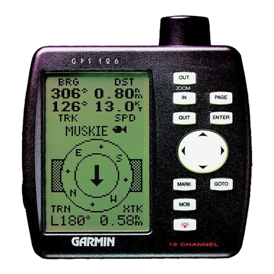
- Page 1 GPS 126/128 Marine Navigator GPS 126 shown ZOOM O w n e r ’ s M a n u a l & R e f e r e n c e ®...
- Page 2 GARMIN. Information in this document is subject to change without notice. GARMIN reserves the right to change or improve its products and to make changes in the content without obligation to notify any person or organization of such changes or improvements.
- Page 3 Due to the simi- larity between the GPS 126 and GPS 128, we have addressed both units in one manual. This manual is organized into four sections for your conve-...
- Page 4 NAVigation AID (NAVAID), any NAVAID can be misused or misinterpreted and, therefore, become unsafe. Use the GPS 126/128 at your own risk. To reduce the risk of unsafe operation, carefully review and understand all aspects of this Operator’ s Manual and thoroughly practice operation using the simulator mode prior to actual use.
-
Page 5: Table Of Contents
INTRODUCTION Table of Contents SECTION ONE Introduction Glossary ..........1 Navigation Basics . -
Page 6: Glossary
INTRODUCTION Glossary The GPS 126/128 is a powerful navigation tool that can guide you any- where in the world. To better understand its operation and capabilities, it may be helpful to review the basic terms and concepts briefly explained below. - Page 7 Grid Coordinate system that projects the earth on a flat surface, using square zones for position measurements. UTM/UPS and Maidenhead formats are grid systems. Ground Speed The velocity you are traveling relative to a ground position. Latitude The north/south measurement of position perpendicular to the earth’ s polar axis.
-
Page 8: Navigation Basics
000º, east as 090º, south as 180º, and west as 270º. The diagram and compass rose below provide a graphic illustration of the navigation terms used by the GPS 126/128. More information on basic navigation and GPS are available at your local library or bookstore. -
Page 9: Keypad Usage & Data Entry
Turns the unit on and off and activates screen backlighting. Scrolls through the main data pages in sequence and returns display from a submenu page to the main page. Captures a position and dis- plays the mark position page. Displays the GOTO page with the waypoint highlighted for GOTO operation. -
Page 10: Primary Pages
Position Page Primary Pages Before we start the tour, let’ s briefly look at the five primary information pages used for the GPS 126/128. To switch between pages press either the keys (see below). Satellite Page The Satellite Page shows satellite positions and signal strength. -
Page 11: Primary Pages
Navigation Page A navigation page gives you steering guidance when going to a waypoint. The GPS 126/128 has two naviga- tion page choices: the Highway Page and the Compass Page. The Highway Page is the default and will be briefly explained here. -
Page 12: Power On & Marking A Position
The tour will take you through the receiver’ s basic features and functions as you move about on the water and assumes that the GPS 126/128 is turned on and initialized, (see page 52 for initialization proce- dure) and that you have not changed any of the factory settings (units of measure, selectable fields, etc.). -
Page 13: Position Page And Map
Position Page (or whatever page was displayed M key). The ‘DOCK’ waypoint prior to pressing the is now stored in the GPS 126/128’ s memory, and will remain there until you manually remove it or clear the receiver’ s memory. For more on waypoint management, see pages 19-24. -
Page 14: Map Pages
GETTING STARTED Position and Map Pages The Map Page displays your present position as a diamond icon and provides a real-time graphic “bread- crumb” display of your track right on the screen. The moving map’s default screen orientation is track- up. -
Page 15: Going To A Waypoint
Going To a Waypoint Once you’ve stored the “CHANNL” waypoint in memory, you can use the GPS 126/128 to guide you to it by performing a simple GOTO. A GOTO is nothing more than a straight-line course from your present posi- tion to the destination you’ve selected. -
Page 16: Compass Page & Cancelling A Goto
Going To a Waypoint (continued) The GPS 126/128’ s Highway Page provides graphic steering guidance to a destination, with an emphasis on a straight-line course to the desired waypoint and the distance and direction you are off course. The bearing and distance to a waypoint–along with your current... -
Page 17: Clearing The Map Display, Adjusting Contrast, & Power Off
‘CANCEL GOTO?’ prompt at the bottom of the page and press Clearing a Cluttered Map Display After you’ve used the GPS 126/128 for a few trips, you may find that your map display has become a bit messy from keeping track of your every move. For practice, let’... -
Page 18: Satellite Page
Satellite Page Status Field The GPS 126/128’ s Satellite Page displays the status of various receiver functions. The status information will help you understand what the GPS 126/128 is doing at any given time, and will tell you whether or not the receiver has calculated a position fix. -
Page 19: Backlighting
The status will be shown as one of the following condi- tions: Searching— the GPS 126/128 is looking for any available satellites in view. AutoLocate— the GPS 126/128 is initializing and collecting new almanac data. -
Page 20: Position Page & User Selectable Fields
Memory Erase Function You may erase the GPS 126/128’ s memory in four quick steps. This will cause all stored data to be deleted, including routes, waypoints, and the track log. - Page 21 Position Page (continued) Directly below the graphic compass tape are the track and speed fields. Track is the compass direction representing your actual course over the ground, and Speed is how fast you’re moving. Below track and speed are two user-selectable fields. Both user selec- table fields can display a variety of information that will aid in navigation The left field offers options for TRIP (default), AVSPD, MXSPD, TTIME, and ELPSD.
-
Page 22: Marking A Position & Position Averaging Function
12– or– 24 hour clock (see system setup page 46). Marking A Position The GPS 126/128 allows you to mark and store up to 500 positions as waypoints. A waypoint can be entered by taking an instant electronic fix, by manually entering coordinates (pg. -
Page 23: Waypoint Pages & Managing Waypoints
The GPS 126/128 positioning averaging function will help reduce the effects of selective availability when marking a waypoint. Note: As the GPS 126/128 calculates the FOM, it will rapidly change before it stabilizes on one number. 1. After you have pressed the ‘AVERAGE?’... -
Page 24: Waypoint List
2. Press Waypoint List Page The waypoint list page provides a complete list of all waypoints currently stored in the GPS 126/128 and their respective waypoint symbols. The total number of empty and used waypoints is also indicated. From the... -
Page 25: Proximity Waypoints
Note: This feature is handy for deleting temporary waypoints created by the TracBack function. Proximity Waypoints The GPS 126/128’ s proximity waypoint function warns you when you are getting too close to hazardous waypoints. This function allows you to create up to nine proximity waypoints and designate an alarm circle for each waypoint. -
Page 26: Waypoint Definition Page
REFERENCE Waypoint Definition & Reference Waypoints 126/128’s advanced waypoint plan- ning features allow you to create new waypoints and practice navigation with- out ever setting foot out- side. If you create a new way- point by entering coordi- nates from a map, you may want to re-mark the waypoint’s exact position... -
Page 27: Waypoint Symbols
6. Press to confirm the ‘DONE?’ prompt. Waypoint Symbols The GPS 126/128 allows you to select one of 16 symbols for each waypoint for easy recognition on the map display. From the symbol page, you may also select how the waypoint appears on the map. -
Page 28: Scanning Waypoints
Can’t be Deleted” message. Scanning Waypoints As you manually enter a waypoint’ s name, the GPS 126/128’ s waypoint scanning feature will automatically display the first numerical or alphabetical match of the character you have entered. If you have more than one... -
Page 29: Selecting A Goto Destination
Selecting a GOTO Destination The GPS 126/128 provides four ways to navigate to a destination: GOTO, MOB, TracBack, and route navi- gation. The most basic method of selecting a destina- tion is the GOTO function, which lets you choose any stored waypoint as the destination and quickly sets a direct course from your present position. -
Page 30: Tracback Navigation
, highlight ‘TRACBACK?’, and press Once the TracBack function has been activated, the GPS 126/128 will take the track log currently stored in memory and divide it into segments called legs. Up to 30 temporary waypoints will be created to mark the most significant features of the track log in order to duplicate your exact path as closely as possible. - Page 31 • If there are not enough available waypoints in memory to create a TracBack route, you will be alerted with a ‘waypoint memory full’ message, and the receiver will use any available waypoints to create a TracBack route with an emphasis on the track log closest to the destination (the oldest track log point in memory).
-
Page 32: Route Navigation
The last form of navigating to a destination with the GPS 126/128 is to create a user-defined route. The GPS126/128 lets you create and store up to 20 routes of 30 waypoints each. The route navigation feature lets you plan and navigate a course from one place to another using a set of pre-defined waypoints. -
Page 33: Route Definition
Route Definition Page Comment Field Desired Track of Leg Copy Field Function Prompts The bottom of the route definition page features ‘function’ fields which let you copy, clear, invert, or activate the displayed route. Routes 1-19 are used as storage routes, with route 0 always serving as the active route you are navigating. -
Page 34: Creating And Using Routes
REFERENCE Using Routes You may use up to 16 characters to custom name a route. The default name will be the first and last waypoint in the route. To activate a route, high- light the ‘ACT?’ prompt and press ENTER. Creating and Navigating Routes To create a route from the route definition page: 1. -
Page 35: Active Route
Active Route Page Once a route has been activated, the active route page will display the waypoint sequence of your route with the estimated time enroute (ETE) at your present speed and the distance to each waypoint. As long as you are navigating an active route, the active route page will become part of the main page sequence of the unit. - Page 36 On-Route GOTO At the beginning of this section, we mentioned that the GPS 126/128 will automatically select the route leg closest to your position as the active leg. This may mean that you are not navigating to the first waypoint in the active route.
-
Page 37: Using The Compass & Highway
Using the Navigation Pages Once you’ve selected a GOTO destination or acti- vated a TracBack, MOB, or Route, the GPS 126/128 will provide graphic steering guidance to the destina- tion with one of two navigation pages: Highway Page Highway Page (default) provides a graphic •The... - Page 38 REFERENCE Navigation Pages Use the user-selectable fields to customize the navigation pages. The turn option will show you the number of degrees you need to turn to head directly to your destina- tion. Selecting a User-Defined Navigation Page (cont.) User-Selectable Field The fields located in the lower corners of both pages are user-selectable fields that allow you to display a vari-...
-
Page 39: Highway Page
Waypoint Graphic Highway User Selectable Fields The GPS 126/128’ s Highway Page provides graphic steering guidance to a destination waypoint, with a greater emphasis on the straight-line desired course and the distance and direction you are off course. The bear- ing and distance to a waypoint–along with your current... - Page 40 ETE, ETA, CTS, XTK, VMG, or TRN. When you are one minute away from your destina- tion (based on your current speed and track over ground), the GPS 126/128 will alert you with a flashing on-screen message box. Distance to...
-
Page 41: Map Page, Zooming, & Panning
Map Page The GPS 126/128 features a powerful real-time moving map that does much more than just plot your course and route. The Map Page also provides you with a target cursor that will let you pan ahead to nearby... - Page 42 REFERENCE Zooming, Panning, & Pointing A crosshair will appear when you activate the pan function. The distance and direction of the crosshair from your current position will be shown in the upper corners of the Map Page. On-Screen Pointing The crosshair will “snap” to displayed waypoints, which allows you to quick- ly review or GOTO the...
-
Page 43: Map Page & Track Log Setup
Zooming, Panning, & Pointing (continued To go to a waypoint highlighted on the map: 1. Press the key.The GOTO waypoint page will appear with the waypoint’s name highlighted. 2. Press the key to confirm. To stop panning and display present position: 1. - Page 44 From the waypoint definition page, you can also define how each individual waypoint is displayed on the map. The GPS 126/128 displays waypoints as a name with a corresponding symbol (e.g., “nearest fuel” and a gas pump symbol), a symbol only (e.g., a fish symbol), or a 16-character comment and corresponding symbol (e.g., “great view”...
- Page 45 . Select ‘YES’ or ‘NO' and press Track Setup Page The track setup page manages the GPS 126/128’ s track log data. From this page, you can select whether to record a track log and define how it is recorded.
-
Page 46: Track Log
REFERENCE Track Log Management The track setup menu lets you instantly change track features directly from the Map Page. Clear the track log any time your screen gets clut- tered or when starting a new TracBack. Track Method The stored track method determines how often positions are stored in the track log. -
Page 47: Menu Page & Distance/Sun Calculation
Menu Page The GPS 126/128’ s Menu Page provides access to additional pages (submenus) that are used to select and customize operation and navigation setup. These eight pages are divided into categories by function. We’ve already gone over the waypoint and route management pages in their respective sections. -
Page 48: Interface Setup & Dgps Interface
GARMIN GPS units or a GARMIN GPS and a PC. There are ten data transfer options: send alm, send wpt, send trk, send rte, send prx, request alm, request wpt, request trk, request rte, request prx. - Page 49 DGPS operation. You may also monitor the DGPS status from the status field on the interface page. The GPS 126/128 will display one of three alert mes- sages concerning DGPS operation: No DGPS Position— there is not enough data available to compute a DGPS position.
-
Page 50: System Setup
Appendix C. System Setup The system setup page is used to select the operat- ing mode, time offset, and screen preferences. The GPS 126/128 has two operating modes: Normal Mode operates the unit using satellite • tracking information. Simulator Mode allows you to operate the unit •... -
Page 51: Navigation Setup
CDI scale, units, and heading information. Position Formats The default position format for the GPS 126/128 is latitude and longitude in degrees and minutes (hdddºmm.mmm’). You may also select degrees, min- utes and seconds (hdddºmm’... -
Page 52: Map Datums
1. Highlight the ‘cdi scale’ field, and press 2. Select the desired setting, and press Units of Measure The GPS 126/128 lets you select statute (default), nautical, or metric units of measure for all ‘speed’ and ‘distance’ fields. . Enter values for... -
Page 53: Magnetic Heading Reference
2. Select the desired unit of measure, and press Speed Filter The speed filter allows you to determine how the GPS 126/128 responds to changes in track or ground speed. Three settings are available: automatic, on, or off. The ‘Auto’ setting is the default and will monitor changes in your current track and speed and adjust the receiver’... -
Page 54: Alarms Setup
Alarms Setup The alarms setup page is used to set the three alarms available on the GPS 126/128: the anchor drag alarm, arrival alarm, and CDI alarm. The anchor drag alarm will sound if your boat has moved outside a range measured from a central point (your position). -
Page 55: Navigation Simulator
Navigation Simulator The GPS 126/128’ s simulator mode lets you prac- tice all aspects of its operation without active satellite acquisition. You can plan and practice trips, enter new waypoints and routes, and save them for use during normal operation. -
Page 56: Appendix A--Initialization
•Select Country––allows you to initialize the receiver by selecting your present position from a list of countries in the GPS 126/128’ s internal data- base. This may speed up the initialization process. •Autolocate ––allows the GPS 126/128 to initial- ize itself and calculate a position fix without know- ing your present position. -
Page 57: Initialization Troubleshooting
500 miles of your present position. 5. Press to finish. The GPS 126/128 will now begin searching for the appropriate satellites for your location and should acquire a position within 3-5 minutes. You can verify that you have acquired a position by watching the Satellite Page transition to the Position Page (provided you haven’t pressed any other buttons) or by looking... -
Page 58: Appendix B-Installation
APPENDIX B Installation Mounting the GPS 126 The GARMIN GPS 126 should be mounted in an exposed location with an unobstructed view of the sky. The unit comes with a gimbal bracket that can be used to surface mount the unit. When choosing a location... - Page 59 (not included). 3. Fasten the bracket to the surface using the appropri- ate fasteners. 4. Insert the GPS 128 into the mounting bracket. 5. Screw the two mounting knobs through the bracket and into the GPS 128.
- Page 60 1. Cut a 4.15” W x 4.67” H hole in panel. 2. Place GPS 128 into hole from the front until its flange rests against the mounting surface. 3. From the back side of the panel, loosely attach the bracket such that the slot in the ratchet area points away from the mounting panel.
- Page 61 3. Once the GPS 128 has been installed, connect the cable to the antenna connector on the back of the display unit. Make sure that you turn the antenna...
-
Page 62: Appendix C-Specifications & Wiring
The GPS 126/128 is constructed of high quality materials and should not require user maintenance. Should your unit ever need repair, please take it to an authorized GARMIN ser- vice center or contact the GARMIN customer service department. The GPS 126/128 has no user serviceable parts. Never attempt any repairs yourself. -
Page 63: Specifications
To connect an external alarm, connect the ground side of the alarm device to the YELLOW harness lead. (100 mA DC load max.) The following interface formats are sup- ported by the GPS 126/128 for driving three NMEA devices: NMEA 0180, NMEA 0182, NMEA 0183 version 1.5:... -
Page 64: Appendix D-Messages And Time Offsets
RTCM Input has Failed—DGPS data being received has been lost. You are no longer receiving the beacon signal. Searching the Sky—The GPS 126/128 is in searching the sky for almanac data or the unit is in AutoLocate The GPS 126/128 uses a flashing on-screen message indicator to alert you to important information. -
Page 65: Time Offsets
Transfer has been Completed—The receiver is finished uploading or downloading information to the connected device. WPT Memory is Full—You have used all 500 waypoints in the GPS 126/128. Delete unwanted waypoints to make room for new entries. Time Offset Chart The table below gives approximate UTC time offset for various longitudi- nal zones. -
Page 66: Appendix E--Map Datums
APPENDIX E Map Datums the GPS 126/128 Menu page abbreviations are listed first, followed by the corresponding map datum name and area. The default map datum for the GPS 126/128 is WGS 84. Adindan Adindan- Ethiopia, Mali, Senegal, Sudan Afgooye Afgooye- Somalia AIN EL ABD ‘70... - Page 67 Mahe 1971 Mahe 1971- Mahe Island Marco Astro Marco Astro- Salvage Island Massawa Massawa- Eritrea (Ethiopia) Merchich Merchich- Morocco Midway Ast ‘61 Midway Astro ‘61- Midway Minna Minna- Nigeria NAD27 Alaska North American 1927- Alaska NAD27 Bahamas North American 1927- Bahamas (excluding San Salvador Island) NAD27 Canada...
-
Page 68: Appendix F--Index
APPENDIX F Index Activating a Route ..30 Active Route Page ..31 Altitude (ALT) ... . .18 Antenna Installation ..57 AutoLocate™... - Page 69 Magnetic Heading ..49 Man Overboard ..25 Map Cursor ...37 Map Datums ..48, 62 Map Orientation .
- Page 70 APPENDIX f Index Units of Measure ..48 User-defined route ..30 User Grid ... .48 Using the Keypad ..5 Using the Position Page .
-
Page 71: Limited Warranty
GARMIN International warrants this product to be free from defects in materials and workmanship for one year from the date of purchase. GARMIN will at its sole option, repair or replace any com- ponents which fail in normal use. Such repairs or replacement will be made at no charge to the customer for parts or labor. - Page 72 NOTES...
- Page 74 1200 E. 151st Street, Olathe, KS USA 66062 GARMIN (Europe) Ltd. - Unit 5, The Quadrangle, Abbey Park, Romsey, UK SO51 9AQ GARMIN (Asia) Corp., 4th Fl., No. 1, Lane 45, Pao-Hsing Road, Hsin Tein, Taiwan R.O.C. Part Number 190-00151-00 Rev. A Printed in Taiwan...