Honeywell VISTA 15P - Ademco 6 Zone Control Panel Installation And Operation Manual
Ademco vista series
Hide thumbs
Also See for VISTA 15P - Ademco 6 Zone Control Panel:
- User manual (64 pages) ,
- Installation manual (24 pages)

Related Manuals for Honeywell VISTA 15P - Ademco 6 Zone Control Panel


Summary of Contents for Honeywell VISTA 15P - Ademco 6 Zone Control Panel
- Page 1 ADEMCO VISTA SERIES VISTA-20P / VISTA-20PSIA VISTA-15P / VISTA-15PSIA Security Systems Installation and Operation Guide K5305-1V8 4/09 Rev. A...
- Page 2 RECOMMENDATIONS FOR PROPER PROTECTION The Following Recommendations for the Location of Fire and Burglary Detection Devices Help Provide Proper Coverage for the Protected Premises. Recommendations For Smoke And Heat Detectors With regard to the number and placement of smoke/heat detectors, we subscribe to the recommendations contained in the National Fire Protection Association's (NFPA) Standard #72 noted below.
-
Page 3: Table Of Contents
Table Of Contents Features and Installation Highlights......................1-1 Capabilities and Functions..............................1-1 Compatible Devices ................................1-2 Important Installation Highlights (Installer Please Read) .....................1-2 Mounting and Wiring the Control .........................2-1 Installing the Control Cabinet and PC Board ........................2-1 Cabinet and Lock .................................2-1 Mounting the PC Board Alone (no RF Receiver) ......................2-1 Mounting Board with RF Receiver..........................2-1 Auxiliary Device Current Draw Worksheet........................2-2 AC Power, Battery, and Ground Connections ........................2-3... - Page 4 Table Of Contents System Communication and Operation .......................3-1 Panel Communication with Central Station ........................3-1 Report Code Formats.................................3-1 Ademco Contact ID ® .................................3-3 Uploading/Downloading via the Internet .........................3-4 System Security Codes ..............................3-5 Panic Keys..................................3-7 Setting the Real-Time Clock .............................3-7 Various System Trouble Displays .............................3-8 Testing the System.............................4-1 About Test Procedures...............................4-1 System Test..................................4-1...
-
Page 5: Features And Installation Highlights
• Via Standard Phone Line: Use an IBM compatible computer, Compass downloading Downloading via Phone Line or software, and a compatible HAYES or CIA modem specified by Honeywell. • Via Internet: supports Upload/Download via the Internet/Intranet when used with an Internet appropriate communications device (ex. -
Page 6: Compatible Devices
Installation and Setup Guide Compatible Devices Device VISTA-20P VISTA-15P Notes Addressable Keypads 6150 Fixed-Word Keypad, 6160 Alpha Keypad, 6150V Fixed-Word Display Voice Keypad, 6160V Alpha Display Voice Keypad, 6150RF Keypad/Transceiver Touch Screen (AUI) Touch Screen (AUI) devices are in addition to the 8 Devices addressable keypads. -
Page 7: Mounting And Wiring The Control
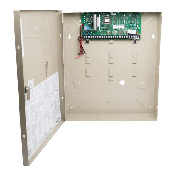
S E C T I O N Mounting and Wiring the Control Installing the Control Cabinet and PC Board Cabinet and Lock 1. Mount the control cabinet to a PUSH ON LOCK sturdy wall in a clean, dry area, CHECK UNTIL IT SNAP IS SEATED... -
Page 8: Auxiliary Device Current Draw Worksheet
Installation and Setup Guide CABINET CABINET BOARD SUPPORTING RECEIVER CIRCUIT BOARD SLOTS CIRCUIT BOARD MOUNTING CLIP CONTROL CIRCUIT BOARD DETAIL A SIDE VIEW MOUNTING CLIP OF BOARD - SUPPORTING SLOTS INSTALLATION WITH RECEIVER CIRCUIT BOARD ANTENNA SCREW GROUNDING WHITE BLACK MOUNTING MOUNTING MOUNTING... -
Page 9: Ac Power, Battery, And Ground Connections
Mounting and Wiring the Control AC Power, Battery, and Ground Connections 1321 Transformer Wire Run Chart Connect the 1321 Transformer (1321CN in Canada) to terminals 1 and 2 on the Distance from control Wire Size control board. See Wire Run Chart for Up to 50 feet # 20 wire size to use. -
Page 10: Sounder (Bell) Connections
Installation and Setup Guide Sounder (Bell) Connections Basic Connections Make sounder connections to alarm output terminals 3 (+) and 4 (–). • The 12VDC sounder output activates when an alarm occurs. • Total current drawn from this output cannot exceed 2 amps (going beyond 2 amps will overload the power supply, or may cause the electronic circuit protecting the sounder output to trip). -
Page 11: Keypad Notes
Mounting and Wiring the Control Keypad Notes Set device addresses. Refer to the instructions included with the devices and set each address according to the Table of Device Addresses. See Keypad Programming Fields (fields *190-*196) in Section 4. Data Field Programming for details on enabling keypad addresses, assigning keypad partitions and selecting keypad sounding options. -
Page 12: Hardwire Zones And Zone Expansion
Installation and Setup Guide Hardwire Zones and Zone Expansion Hardwire Zones Normally Open Zones/ N.O. EOLR Zones 1. Connect open circuit devices in parallel across the loop; for EOLR zones, connect the EOLR across the loop wires at the last device. 2. -
Page 13: Smoke Detector Notes
Mounting and Wiring the Control • • • • Fire Verification (zone type 16): The control panel will “verify” a fire alarm by Smoke Detector Notes resetting the smoke detectors after the first alarm trigger, and then waiting up to 90 seconds for a second alarm trigger. -
Page 14: Installing The Rf Receiver And Wireless Transmitter Zones
Installation and Setup Guide 4229 RELAY RELAY CONNECTOR DIP SWITCH FOR SETTING ADDRESS EITHER OR BOTH CAN BE USED AND ZONE "A" RESPONSE TERMINALS ON CONTROL PANEL RELAY 4-PIN CONSOLE PLUG DATA OUT (>) NO C NC (TERM 6) TO CONTROL TAMPER JUMPER POSITION 4229 IN CABINET (–) GROUND... -
Page 15: Installing A 5800Tm Module
Mounting and Wiring the Control • Use this module only if you are using one or more wireless bi-directional keypads or Installing a 5800TM Module keyfobs with a wireless Receiver; 5800TM is not necessary if using a Transceiver (e.g., 5883). •... -
Page 16: Installing A Keyswitch
Installation and Setup Guide Installing a Keyswitch Keyswitch Connections 1. Connect the 4146 keyswitch's normally open momentary switch to a zone’s (2-8) terminals. Remove the 2000 ohm EOL resistor if connected across the selected zone. 2. Using a standard keypad cable as shown: Connect the yellow and white keyswitch wires to trigger connector pin 3 (+12V). -
Page 17: Connecting Relay Modules, Powerline Carrier Devices And Output Triggers
Mounting and Wiring the Control Connecting Relay Modules, Powerline Carrier Devices and Output Triggers 4204/4229 Relay Modules 1. Mount either remotely or in the control panel. 2. Connect each module to the control’s keypad terminals and set the device addresses as previously described in the Connecting Keypads and Other Addressable Device section. -
Page 18: On-Board Triggers
Installation and Setup Guide On-Board Triggers Connect field wiring to the desired trigger pin on the 8-pin trigger connector centrally located above the terminal strip. • If using 1361X10 transformer and powerline carrier devices, use the SA4120XM-1 cable (part of 4120TR Trigger Cable). See Wiring the AC Transformer section for transformer connections. -
Page 19: Phone Line/Phone Module, And Audio Alarm Verification (Aav) Connections
Mounting and Wiring the Control Phone Line/Phone Module, and Audio Alarm Verification (AAV) Connections Phone Line Connect incoming phone line and handset wiring to the main terminal block (via an RJ31X jack) as shown in the Summary of Connections diagram at the back of this manual. -
Page 20: Audio Alarm Verification Connections
Installation and Setup Guide Audio Alarm Verification Using the UVS System with UVCM Module Connections The UVS system provides audio alarm verification via the phone line. (UVS System) • Refer to the connection diagrams below. One diagram shows connections when a 4286 Phone Module is used, the other shows connections when the 4286 is not used. -
Page 21: Audio Alarm Verification Connections
Mounting and Wiring the Control Audio Alarm Verification Using the AVS System with AVS Module and AVST Remote Stations Connections The AVS system provides audio alarm verification via the phone line or via AlarmNet if (AVS System) the GSMV module is used as the communication device. Refer to the instructions included with the AVS system for installation procedures. - Page 22 Installation and Setup Guide RING RJ31X RING INCOMING TELCO PREMISES PHONES DIRECT CONNECT CORD VISTA SERIES RESIDENTIAL CONTROL KEYPAD TRIGGER HEADER INCOMING HANDSET PHONE LINE ECP TERMINALS DATA DATA GND AUX AVST STATION IMPORTANT: SPEAKERS DO NOT CONNECT ANY OTHER ECP DEVICES TO PANEL.
-
Page 23: System Communication And Operation
S E C T I O N System Communication and Operation Panel Communication with Central Station This system accommodates several formats for reporting alarms and other system conditions to the Central Station. The process of a successful transmission consists of both the method of communication between the control panel and the Central Station receiver;... - Page 24 Installation and Setup Guide The following table lists codes for reports sent in different formats: Code for Code for Type of 3+1/4+1 3+1/4+1 Code for Report Standard Expanded Alarm SSS(S) A SSS(S) A SSSS AZ AAA(A) Z Trouble SSS(S) T SSS(S) T SSSS Tt TTT(T) t...
-
Page 25: Ademco Contact Id
System Communication ® Ademco Contact ID ® The Ademco Contact ID Reporting Format comprises the following: 4-digit or 10-digit subscriber number (depending on format selected). 1-digit event qualifier (“new” or “restore”). 3-digit event code. 2-digit Partition No. 3-digit zone number, user number, or system status number (see the following page). ®... -
Page 26: Uploading/Downloading Via The Internet
Installation and Setup Guide Uploading/Downloading via the Internet UL: Up/downloading via the Internet has not been evaluated by UL. This control, when used with a compatible Internet/Intranet Communication Device, supports upload/download programming capability via the Internet using the AlarmNet network or, depending on the communication module used, a Private local area network (Intranet). -
Page 27: System Security Codes
System Operation System Security Codes The systems provides one Installer code, one System Master code, plus a set of other user codes intended for other users of the system. These codes can each be assigned one of 5 authority levels, which determine the functions each code can perform as listed in the table below. - Page 28 Installation and Setup Guide Keypad Functions The following is a brief list of system commands. For detailed information concerning system functions, refer to the User's Manual. For Touch Screen style keypad users, refer to the separate Touch Screen keypad (AUI) User’s Guide. Voice Keypads The 6150V/6160V Voice Keypads provide the following features: •...
-
Page 29: Panic Keys
System Operation SUMMARY OF ARMING MODES Arming Mode Features for Each Arming Mode Exit Delay Entry Delay Perimeter Armed Interior Armed AWAY STAY NIGHT-STAY only those zones listed in Night- Stay zone list INSTANT MAXIMUM Panic Keys There are three Panic keys (A, B, and C) that, if programmed, can be used to manually initiate alarms and send a report to the central station. -
Page 30: Various System Trouble Displays
Installation and Setup Guide Various System Trouble Displays Alpha Display Fixed Disp. Meaning ALARM CANCELED will appear if an exit or interior zone contained a fault during closing at the time the Exit Delay ended (e.g., exit door left open), but the system was disarmed during the Entry Delay time. -
Page 31: Testing The System
S E C T I O N Testing the System About Test Procedures After the installation is complete, you should perform the following tests: System Test: Checks that all zones have been installed properly and the system responds to faults. Dialer Test: Checks that the phone connection to the central station is working properly. -
Page 32: Go/No Go Test Mode
Installation and Setup Guide NOTES: • All BR type units must physically be activated to clear the display. • When one button of a transmitter (RF, UR, or BR) is activated, all zones assigned to other buttons on that transmitter are cleared from the display. This also applies to 5816 and 5817 transmitters, which have multiple loops (zones). -
Page 33: Specifications & Accessories
S E C T I O N Specifications & Accessories Security Control 1. Physical: 12-1/2” W x 14-1/2” H x 3” D (318mm x 368mm x 76mm) 2. Electrical: VOLTAGE INPUT: 16.5VAC from plug-in 25VA transformer, ADEMCO 1321 (in U.S.A.) RECHARGEABLE BACKUP BATTERY: 12VDC, 4AH (sealed lead acid type). - Page 34 Installation and Setup Guide 2-Wire Smoke Detector: System Sensor Model No. Detector Type Photoelectric w/heat sensor, direct wire 2300TB Photoelectric, direct wire 2400 Photoelectric w/heat sensor, direct wire 2400TH Photoelectric 2451 w/B401B base Photoelectric w/heat sensor 2451TH w/B401B base Ionization, direct wire 1400 Ionization 1451 w/B401B base...
-
Page 35: Regulatory Agency Statements
S E C T I O N Regulatory Agency Statements FEDERAL COMMUNICATIONS COMMISSION (FCC) STATEMENTS The user shall not make any changes or modifications to the equipment unless authorized by the Installation Instructions or User's Manual. Unauthorized changes or modifications could void the user's authority to operate the equipment. CLASS B DIGITAL DEVICE STATEMENT NOTE: This equipment has been tested and found to comply with the limits for a Class B digital device, pursuant to part 15 of the FCC Rules. - Page 36 Installation and Setup Guide UL NOTICES Entry Delay No. 1 and No. 2 (fields ∗ 35, ∗ 36) cannot be greater than 30 seconds for UL Residential Burglar Alarm installations, and entry delay plus dial delay should not exceed 1 minute. For UL Commercial Burglar Alarm installations, total entry delay may not exceed 45 seconds.
-
Page 37: Limitations And Warranty
S E C T I O N Limitations and Warranty WARNING THE LIMITATIONS OF THIS ALARM SYSTEM While this System is an advanced design security system, it does not offer guaranteed protection against burglary, fire or other emergency. Any alarm system, whether commercial or residential, is subject to compromise or failure to warn for a variety of reasons. - Page 38 Installation and Setup Guide – INDEX – 1321 ......... 1-2, 2-3 Cabinet ..........2-1 MODel 112 ........2-10 1321 AC Transformer ....2-11 CALIFORNIA STATE FIRE Modem ..........3-8 1361X10 ....2-3, 2-11, 2-12, 5-2 MARSHALL.........2-2 Momentary Switch ......2-10 3+1 and 4+1 Standard Formats ..3-1 Caller ID Unit .........
- Page 39 ONLY VISTA-20P ZONE ZONE ZONE ZONE ZONE ZONE ZONE CONTACTS TAMPER GROUPS) BOTH EITHER FROM ZONES ADDITIONAL OPTIONAL ZONE DETECTORS SMOKE 2-WIRE USED DATA KEYPAD YELLOW: KEYPAD FROM DATA GREEN: KEYPAD RED: (TRIG. OUTPUT (TRIG. OUTPUT RETURN GROUND KEYPAD BLACK: Figure 17.
- Page 40 WARRANTY INFORMATION For the latest warranty information, please go to: www.honeywell.com/security/hsc/resources/wa 2 Corporate Center Drive, Suite 100 P.O. Box 9040, Melville, NY 11747 Copyright © 2004 Honeywell International Inc. www.honeywell.com/security ÊK5305-1V88Š K5305-1V8 4/09 Rev. A...