HP DL370 - ProLiant - G6 Performance User Manual
Hp proliant dl/ml370 g6 server user guide
Hide thumbs
Also See for DL370 - ProLiant - G6 Performance:
- Quickspecs (56 pages) ,
- Introduction manual (22 pages) ,
- Introduction manual (22 pages)

Related Manuals for HP DL370 - ProLiant - G6 Performance


Summary of Contents for HP DL370 - ProLiant - G6 Performance
-
Page 1: User Guide
HP ProLiant DL/ML370 G6 Server User Guide Part Number 513482-001 March 2009 (First Edition) - Page 2 © Copyright 2009 Hewlett-Packard Development Company, L.P. The information contained herein is subject to change without notice. The only warranties for HP products and services are set forth in the express warranty statements accompanying such products and services. Nothing herein should be construed as constituting an additional warranty. HP shall not be liable for technical or editorial errors or omissions contained herein.
-
Page 3: Table Of Contents
Contents Component identification ....................... 7 Front panel components ..........................7 Front panel LEDs and buttons ........................8 Systems Insight Display LEDs ........................9 Systems Insight Display LED combinations..................... 9 Rear panel components..........................11 Rear panel LEDs ............................12 System board components........................13 System maintenance switch...................... - Page 4 Installing the operating system........................37 Registering the server..........................38 Hardware options installation....................... 39 Introduction ............................39 Processor option............................39 Memory options ............................43 Memory subsystem architecture ....................... 44 Single-, dual-, and quad-rank DIMMs ....................44 DIMM identification ........................45 Memory configurations........................45 General DIMM slot population guidelines ..................
- Page 5 SmartStart software........................99 HP ROM-Based Setup Utility......................100 Array Configuration Utility ......................102 Option ROM Configuration for Arrays ................... 102 HP ProLiant Essentials Rapid Deployment Pack ................102 Re-entering the server serial number and product ID ................. 103 Management tools..........................103 Automatic Server Recovery ......................
- Page 6 POST error messages and beep codes ..................... 129 Regulatory compliance notices ....................130 Regulatory compliance identification numbers ................... 130 Federal Communications Commission notice..................... 130 FCC rating label.......................... 130 Class A equipment........................130 Class B equipment ........................130 Declaration of conformity for products marked with the FCC logo, United States only........131 Modifications............................
-
Page 7: Component Identification
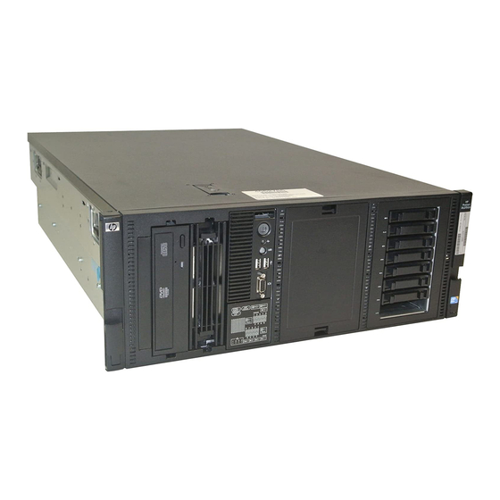
Component identification Front panel components Item Description USB connectors (2) Drive cage blank SAS/SATA drives (8) Front video connector (rack model only) Systems Insight Display Removable media bay DVD-ROM drive Optical drive blank Component identification 7... -
Page 8: Front Panel Leds And Buttons
Front panel LEDs and buttons Item Description Status Power On/Standby button Green = Normal (system on) and system power LED Amber = System in standby, but power still applied Off = Power cord not attached or power supply failure Health LED Green = Normal (system on) Amber = System health is degraded Red = System health is critical. -
Page 9: Systems Insight Display Leds
Systems Insight Display LEDs The HP Systems Insight Display LEDs represent the system board layout. Item Description Status Power cap To determine Power cap status, see "Systems Insight Display LED combinations (on page 9)." AMP Status Green = AMP mode enabled Amber = Failover Flashing amber = Invalid configuration Off = AMP mode disabled... - Page 10 Systems Insight Display Health LED System power Status LED and color Processor (amber) Amber One or more of the following conditions may exist: • Processor in socket X has failed. • Processor X is not installed in the socket. • Processor X is unsupported.
-
Page 11: Rear Panel Components
Rear panel components Item Description Mouse connector Keyboard connector Serial connector iLO 2 connector USB connectors (2) NIC connectors (4) PCI expansion slots Reserved Video connector Power supply bay 2 Power supply bay 1 (populated) Component identification 11... -
Page 12: Rear Panel Leds
Rear panel LEDs Item Description Status UID LED Blue = Activated Flashing blue = System is being managed remotely. Off = Deactivated iLO 2 activity LED Green or flashing green = Network activity Off = No network activity iLO 2 link LED Green = Linked to network Off = No network connection NIC link LED... -
Page 13: System Board Components
System board components Item Description SD card slot Power backplane connector Processor 1 DIMM slots Power supply connector SAS connector B SAS connector A Front panel connector Systems Insight Display connector Front video connector Front USB connector Smart Array P410i memory module Reserved System battery TPM connector... -
Page 14: System Maintenance Switch
Item Description Slot 8 PCIe2 x16 (16, 8, 4, 2, 1) Slot 9 PCIe2 x8 (4, 2, 1) Slot 10 PCIe2 x8 (8, 4, 2, 1) Internal USB connector Processor socket 2 Processor 2 DIMM slots Power supply connector Processor socket 1 (populated) System maintenance switch The system maintenance switch (SW1) is a ten-position switch that is used for system configuration. -
Page 15: Nmi Functionality
Position Description Function Reserved Reserved Reserved Reserved Reserved Reserved When the system maintenance switch position 6 is set to the On position, the system is prepared to erase all system configuration settings from both CMOS and NVRAM. CAUTION: Clearing CMOS and/or NVRAM deletes configuration information. Be sure to properly configure the server or data loss could occur. - Page 16 • SFF hard drives • LFF hard drives Component identification 16...
-
Page 17: Sas And Sata Hard Drive Leds
SAS and SATA hard drive LEDs Item Description Status Fault/UID LED Amber = Drive failure Flashing amber = Fault-process activity Blue = Unit identification is active Off = No fault-process activity Online/activity LED Green = Drive activity Flashing green = High activity on the drive or drive is being configured as part of an array Off = No drive activity... -
Page 18: Dimm Slots
Online/activity Fault/UID LED Interpretation LED (green) (amber/blue) Flashing regularly Amber, flashing Do not remove the drive. Removing a drive may terminate the (1 Hz) regularly (1 Hz) current operation and cause data loss. The drive is part of an array that is undergoing capacity expansion or stripe migration, but a predictive failure alert has been received for this drive. -
Page 19: Fans
Fans Item Description Configuration Fan 1 Redundant Fan 2 Primary Fan 3 Redundant Fan 4 Primary Fan 5 Primary Battery pack LEDs Component identification 19... - Page 20 Item ID Color Description Green System Power LED. This LED glows steadily when the system is powered up and 12 V system power is available. This power supply is used to maintain the battery charge and provide supplementary power to the cache microcontroller.
-
Page 21: Power Supply Backplane Connectors
Power supply backplane connectors Item Description Drive bay 1 power cable Drive bay 2 power cable Drive bay 3 power cable Power supply 1 cable Power supply 2 cable SATA power cable SATA power cable SATA power cable Video adapter power cable Data cable Video adapter power cable Drive cage jumper configuration settings... -
Page 22: Operations
Operations Power up the server To power up the server, press the Power On/Standby button. Power down the server WARNING: To reduce the risk of personal injury, electric shock, or damage to the equipment, remove the power cord to remove power from the server. The front panel Power On/Standby button does not completely shut off system power. - Page 23 Use the key provided with the server to unlock the bezel with a counterclockwise turn. If necessary, remove the tower bezel. Operations 23...
-
Page 24: Extend The Server From The Rack
The middle panel can be removed to access the Systems Insight Display and I/O bezel. The top panel can be removed to access the removable media bays. Extend the server from the rack IMPORTANT: If the server is installed in a telco rack, remove the server from the rack to access internal components. -
Page 25: Remove The Access Panel
After performing the installation or maintenance procedure, slide the server into the rack by pressing the server rail-release latches. Remove the access panel WARNING: To reduce the risk of personal injury from hot surfaces, allow the drives and the internal system components to cool before touching them. CAUTION: Do not operate the server for long periods with the access panel open or removed. -
Page 26: Remove The Air Baffle
Extend the server from the rack (on page 24). Open the locking latch, slide the access panel to the rear of the chassis, and remove the access panel. If the locking latch is locked, use a T-15 Torx screwdriver to unlock the latch. Remove the air baffle Power down the server (on page 22). -
Page 27: Remove The Media Bay Blank
Remove the fan cage. Remove the media bay blank Power down the server (on page 22). Do one of the following: Open or remove the tower bezel, as needed ("Open or remove the tower bezel" on page 22). Extend the server from the rack (on page 24). Remove the access panel (on page 25). -
Page 28: Remove The Dvd-Rom Drive
Remove the DVD-ROM drive Power down the server (on page 22). Do one of the following: Open or remove the tower bezel, as needed ("Open or remove the tower bezel" on page 22). Extend the server from the rack (on page 24). Remove the access panel (on page 25). - Page 29 Remove the hard drive cage blank. Operations 29...
-
Page 30: Setup
Setup Optional installation services Delivered by experienced, certified engineers, HP Care Pack services help you keep your servers up and running with support packages tailored specifically for HP ProLiant systems. HP Care Packs let you integrate both hardware and software support into a single package. A number of service level options are available to meet your needs. -
Page 31: Optimum Environment
Optimum environment When installing the server, select a location that meets the environmental standards described in this section. Space and airflow requirements Tower server In a tower configuration, leave at least a 7.6-cm (3-in) clearance space at the front and back of the server for proper ventilation. -
Page 32: Temperature Requirements
Temperature requirements To ensure continued safe and reliable equipment operation, install or position the system in a well- ventilated, climate-controlled environment. The maximum recommended ambient operating temperature (TMRA) for most server products is 35°C (95°F). The temperature in the room where the rack is located must not exceed 35°C (95°F). CAUTION: To reduce the risk of damage to the equipment when installing third-party options: •... -
Page 33: Rack Warnings
Furthermore, you must be sure that all power distribution devices used in the installation, such as branch wiring and receptacles, are listed or certified grounding-type devices. Because of the high ground-leakage currents associated with multiple servers connected to the same power source, HP recommends the use of a PDU that is either permanently wired to the building’s branch circuit or includes a nondetachable cord that is wired to an industrial-style plug. -
Page 34: Identifying Tower Server Shipping Carton Contents
WARNING: To reduce the risk of personal injury, electric shock, or damage to the equipment, remove the power cord to remove power from the server. The front panel Power On/Standby button does not completely shut off system power. Portions of the power supply and some internal circuitry remain active until AC power is removed. -
Page 35: Installing Hardware Options
• Hardware options • Operating system or application software • Installing hardware options Install any hardware options before initializing the server. For options installation information, refer to the option documentation. For server-specific information, refer to "Hardware options installation (on page 39)."... -
Page 36: Installing The Server Into The Rack
Push the tab into place to secure the power cord. Connect the power cord to the AC power source. WARNING: To reduce the risk of electric shock or damage to the equipment: Do not disable the power cord grounding plug. The grounding plug is an important safety •... -
Page 37: Powering Up And Configuring The Server
WARNING: This server is very heavy. To reduce the risk of personal injury or damage to the equipment: • Observe local occupational health and safety requirements and guidelines for manual material handling. Get help to lift and stabilize the product during installation or removal, especially when the •... -
Page 38: Registering The Server
Registering the server To register the server, refer to the HP Registration website (http://register.hp.com). Setup 38... -
Page 39: Hardware Options Installation
Hardware options installation Introduction If more than one option is being installed, read the installation instructions for all the hardware options and identify similar steps to streamline the installation process. WARNING: To reduce the risk of personal injury from hot surfaces, allow the drives and the internal system components to cool before touching them. - Page 40 Remove the processor socket protective cover. IMPORTANT: Be sure the processor remains inside the processor installation tool. If the processor has separated from the installation tool, carefully re-insert the processor in the tool. Hardware options installation 40...
- Page 41 Align the processor installation tool with the socket and install the processor. Press down firmly until the processor installation tool clicks and separates from the processor, and then remove the processor installation tool. Hardware options installation 41...
- Page 42 Close the processor socket retaining bracket and the processor retaining latch. Open the heatsink retaining latches. Hardware options installation 42...
-
Page 43: Memory Options
Remove the protective cover from the heatsink. CAUTION: To prevent thermal instability and damage to the server, do not separate the processor from the heatsink after assembling. Install the heatsink, and then close the heatsink retaining latches. Install the air baffle. Install the access panel. -
Page 44: Memory Subsystem Architecture
IMPORTANT: This server does not support mixing RDIMMs and UDIMMs. Attempting to mix these two types causes the server to halt during BIOS initialization. The memory subsystem in this server can support RDIMMs or UDIMMs. Both types are referred to as DIMMs when the information applies to both types. -
Page 45: Dimm Identification
Dual- and quad-rank DIMMs provide the greatest capacity with the existing memory technology. For example, if current DRAM technology supports 2-GB single-rank DIMMs, a dual-rank DIMM would be 4- GB, and a quad-rank DIMM would be 8-GB. DIMM identification IMPORTANT: This server does not support mixing RDIMMs and UDIMMs. - Page 46 • Advanced ECC—provides the greatest memory capacity for a given DIMM size, while providing up to 8-bit error correction, depending on the specific DIMM type. This mode is the default option for this server. • Mirrored Memory—provides maximum protection against failed DIMMs. Uncorrectable errors in one channel are corrected by the mirror channel.
-
Page 47: General Dimm Slot Population Guidelines
Lockstep mode uses channel 1 and channel 2. Channel 3 is not populated. Because channel 3 cannot be populated when using Lockstep mode, the maximum memory capacity is lower than Advanced ECC mode. Memory performance with Advanced ECC is also slightly higher. General DIMM slot population guidelines Observe the following guidelines for all AMP modes: •... - Page 48 Lockstep Memory population guidelines For Lockstep memory mode configurations, observe the following guidelines: • Observe the general DIMM slot population guidelines (on page 47). • Always install DIMMs in channels 1 and 2 for each installed processor. • Do not install DIMMs in channel 3 for any processor. •...
-
Page 49: Installing A Dimm
Installing a DIMM CAUTION: To avoid damage to the hard drives, memory, and other system components, the air baffle, drive blanks, and access panel must be installed when the server is powered up. Power down the server (on page 22). Do one of the following: Open or remove the tower bezel, as needed ("Open or remove the tower... - Page 50 • If one fan fails in redundant mode, the server converts to non-redundant mode. • If two fans fail in redundant mode, the server shuts down. WARNING: To prevent personal injury from hazardous energy: Remove watches, rings, or other metal objects. •...
-
Page 51: Redundant Hot-Plug Power Supply Option
Install the redundant fans. Install the fan cage. Install the air baffle. Install the access panel. Do one of the following: Close or install the tower bezel, as needed. Slide the server back into the rack. Power up the server (on page 22). Redundant hot-plug power supply option The server supports a second hot-plug power supply to provide redundant power to the system if the primary power supply fails. -
Page 52: Power Supply Configuration
CAUTION: Always install either a hot-plug power supply or a power supply blank into each bay to maintain proper airflow and cooling in the server. Improper airflow can lead to thermal damage. Power supply configuration CAUTION: All power supplies installed in the server must have the same output power capacity. -
Page 53: Hot-Plug Sas Hard Drive Options
Install the second hot-plug power supply. Connect the power cord to the redundant power supply. Use the power cord management clip to secure the cord and form a service loop. Connect the power cord to the AC power source. Be sure that the power supply LED is green ("Rear panel LEDs"... -
Page 54: Installing A Hot-Plug Sas Hard Drive
Installing a hot-plug SAS hard drive Remove the SAS hard drive blank. Prepare the hard drive. Install the hard drive. Determine the status of the hard drive from the hot-plug SAS hard drive LED combinations ("SAS and SATA hard drive LED combinations"... -
Page 55: Eight-Bay Sff Drive Cage Option
Determine the status of the hard drive from the hot-plug SAS hard drive LED combinations ("SAS and SATA hard drive LED combinations" on page 17). Back up all server data on the hard drive. Remove the hard drive. Eight-bay SFF drive cage option Install the optional eight-bay SFF drive cage in drive cage bay 2 or drive cage bay 3. - Page 56 Save the screws. Using the screws, install the eight-bay SFF drive cage. Connect the SAS cables to an optional SAS controller ("Storage controller option" on page 78). Hardware options installation 56...
-
Page 57: Installing The Eight-Bay Sff Drive Cage (Bay 3)
Route and connect the drive cage bay 2 power cable (BP2) and the SAS cables to the drive cage backplane. Install the fan cage. Install the air baffle. Install the access panel. Do one of the following: Close or install the tower bezel, as needed. Slide the server back into the rack. - Page 58 Remove the DVD-ROM drive (on page 28). Using a T-10 Torx screwdriver, remove the two screws on top of the drive cage. Using a T-15 Torx screwdriver, remove the sleeve from the drive cage. Hardware options installation 58...
- Page 59 Install the drive cage. Using a T-15 Torx screwdriver, install the locking brackets. Connect the SAS cables to an optional SAS controller ("Storage controller option" on page 78). Hardware options installation 59...
-
Page 60: Six-Bay Lff Backplane Option
Route and connect the drive cage bay 3 power cable (BP3) and the SAS cables to the drive cage backplane. Install the fan cage. Install the air baffle. Install the access panel. Do one of the following: Close or install the tower bezel, as needed. Slide the server back into the rack. - Page 61 Open or remove the tower bezel, as needed ("Open or remove the tower bezel" on page 22). Extend the server from the rack (on page 24). Remove the access panel (on page 25). Remove the air baffle (on page 26). Remove the fan cage (on page 26).
- Page 62 Connect the power cable. Route and connect the SAS cables. Install the fan cage. Install the air baffle. Install the access panel. Do one of the following: Close or install the tower bezel, as needed. Slide the server back into the rack. CAUTION: To prevent improper cooling and thermal damage, do not operate the server unless all bays are populated with either a component or a blank.
-
Page 63: Installing The Six-Bay Lff Backplane (Bay 2)
Installing the six-bay LFF backplane (bay 2) To install the component: Power down the server (on page 22). Do one of the following: Open or remove the tower bezel, as needed ("Open or remove the tower bezel" on page 22). Extend the server from the rack (on page 24). - Page 64 The cabling for drive cage bay 1 is not shown for clarity. Connect the SAS cables to an optional SAS controller ("Storage controller option" on page 78) or to an optional SAS expander. Route and connect the SAS cables. Install the fan cage. Install the air baffle.
-
Page 65: Two-Bay Lff Drive Cage Option
Power up the server (on page 22). Two-bay LFF drive cage option To configure this option for drive cage bay 3, locate the three jumper pins on the backplane. Move the jumper from pins 1 and 2 to pins 2 and 3. For more information, see "Drive cage jumper configuration settings (on page 21)."... - Page 66 Using a T-15 Torx screwdriver, install the locking brackets. Connect the drive cage bay 3 power cable (BP3) to the two-bay LFF drive cage backplane. Connect the two-bay LFF drive cage to one of the following: A six-bay LFF backplane. See step 13. An optional SAS controller.
- Page 67 Connect the remaining connector to SAS connector B on the system board. Connect the LED cable to the two-bay LFF drive cage backplane and to the six-bay LFF backplane. Proceed to step 15. Connect the SAS/SATA controller cable: Connect the main branch of the SAS/SATA controller cable to an optional SAS controller ("Storage controller option"...
-
Page 68: Removable Media Device Options
For this cabling scenario, the "2LFF" labeled connector is not used. Coil the excess cable to minimize the impact to airflow. Install the fan cage. Install the air baffle. Install the access panel. Do one of the following: Close or install the tower bezel, as needed. Slide the server back into the rack. - Page 69 Remove the media bay blank (on page 27). Using a T-15 Torx screwdriver, remove the screws from the blank and install them on the device. Slide the media device part of the way into the bay. Connect the server data and power cables to the rear of the device. Slide the media drive fully into the bay until it is seated securely.
-
Page 70: Installing A Full-Height Media Device
Installing a full-height media device Power down the server (on page 22). Do one of the following: Open or remove the tower bezel, as needed ("Open or remove the tower bezel" on page 22). Extend the server from the rack (on page 24). Remove the access panel (on page 25). -
Page 71: Slimline Optical Drive Option
Connect the server data and power cables to the rear of the device. Slide the media drive fully into the bay until it is seated securely. Install the fan cage. Install the air baffle. Install the access panel. Do one of the following: Close or install the tower bezel, as needed. - Page 72 Slide the optical drive into the drive bay. Route and connect the cables: Connect the power and data cable to the optical drive. Connect the power cable to an available system power cable Route and connect the data cable to the system board. Install the fan cage.
-
Page 73: Expansion Board Options
Expansion board options The server supports up to ten PCIe expansion boards. For more information, see "System board components (on page 13)." IMPORTANT: The HP SAS Expander Card and the HP NC524SFP Adapter are not supported in expansion slot 1. To install the component: Power down the server (on page 22). - Page 74 Remove the expansion slot cover. Install the expansion board. Close the expansion slot retainer. Connect any internal cables to the expansion board. Install the air baffle. Install the access panel. Do one of the following: Close or install the tower bezel, as needed. Slide the server back into the rack.
-
Page 75: Hp Nc524Sfp Dual Port 10Gbe Module Option
HP NC524SFP Dual Port 10GbE Module option When installed on the HP NC375i Integrated Quad Port Multifunction Gigabit Server Adapter, the HP NC524SFP Dual Port 10GbE Module provides two 10G NIC connectors for server I/O. If more than one HP NC375i adapter is installed in the server, always install the HP NC524SFP module on the adapter in expansion slot 10. - Page 76 Remove the HP NC375i adapter from expansion slot 10. Install the HP NC524SFP module on the HP NC375i adapter. Hardware options installation 76...
- Page 77 Install the mini-DIMM on the expansion board. Install the HP NC375i adapter in expansion slot 10. Close the expansion board slot retainer. Hardware options installation 77...
-
Page 78: Storage Controller Option
Secure the 10G NIC connectors to the chassis with the retaining screw. Install the RJ-45 plugs on the bottom (rack model) or right (tower model) two RJ-45 connectors on the HP NC375i adapter. Install the air baffle. Install the access panel. Do one of the following: Close or install the tower bezel, as needed. -
Page 79: Hp Sas Expander Card Option
IMPORTANT: For additional installation and configuration information, refer to the documentation that ships with the option. To install the component: Power down the server (on page 22). Do one of the following: Open or remove the tower bezel, as needed ("Open or remove the tower bezel"... -
Page 80: Graphics Adapter Option
For more information, see the documentation that ships with the expander card. Install the fan cage. Install the air baffle. Install the access panel. Do one of the following: Close or install the tower bezel, as needed. Slide the server back into the rack. Power up the server (on page 22). - Page 81 The tower-to-rack conversion kit includes: • Rack-mounting hardware kit • Rack bezel • Front video connector cable • T-15 screws (6) • Screwlocks (2) • This document In addition to the items supplied in the conversion kit, you will also need the following items: •...
- Page 82 For more information, see the server maintenance and service guide. (Optional) Reduce the weight of the server: Remove the power supplies. Remove all LFF hard drives and blanks. Disconnect cabling and remove all devices from the removable media bays. Extend the Systems Insight Display from the chassis. For the remaining steps, the Systems Insight Display is not shown for clarity.
- Page 83 Rear (1) Front (2) Remove the chassis from the tower side panels: Hardware options installation 83...
- Page 84 Disengage the chassis from the tower side panels by pushing the bottom side panel back and by pulling the chassis forward. Lift the chassis up and out of the tower side panels. Hardware options installation 84...
- Page 85 With T-10 Torx screwdriver, remove the tower bezel bracket. Extend the I/O bezel from the chassis. Install the rack bezel using the T-15 screws provided. Hardware options installation 85...
- Page 86 The I/O bezel is not shown for clarity. Remove the front video connector cable blank from the I/O bezel. Hardware options installation 86...
- Page 87 Using a 3/16-in nut driver and the screwlocks, install the front video connector cable. Route the front video connector cable through the front of the chassis. Hardware options installation 87...
- Page 88 Install the I/O bezel. Route and connect the front video connector cable to the front video connector on the system board. Install the Systems Insight Display. Install the SFF drive cages. Install the two-bay LFF drive cage, if removed. Install the DVD-ROM drive, if removed. Connect the drive cables.
-
Page 89: Hp Trusted Platform Module Option
For the location of the system maintenance switch, see the label attached to the access panel.. Install the access panel. Install the server in the rack. See the instructions in the rack-mounting hardware kit. Install the following items: Hard drives and blanks Media blank Power supplies Power up the server. -
Page 90: Installing The Trusted Platform Module Board
Installing the Trusted Platform Module board WARNING: To reduce the risk of personal injury, electric shock, or damage to the equipment, remove the power cord to remove power from the server. The front panel Power On/Standby button does not completely shut off system power. Portions of the power supply and some internal circuitry remain active until AC power is removed. -
Page 91: Retaining The Recovery Key/Password
Install the TPM security rivet by pressing the rivet firmly into the system board. Install the fan cage. Install the air baffle. Install the access panel. Do one of the following: Close or install the tower bezel, as needed. Install the server in the rack. Power up the server (on page 22). - Page 92 Press the Esc key to exit the current menu, or press the F10 key to exit RBSU. Reboot the server. Enable the TPM in the OS. For OS-specific instructions, see the OS documentation. CAUTION: When a TPM is installed and enabled on the server, data access is locked if you fail to follow the proper procedures for updating the system or option firmware, replacing the system board, replacing a hard drive, or modifying OS application TPM settings.
-
Page 93: Cabling
Cabling Storage device cabling guidelines CAUTION: To prevent damage to the equipment, be sure that the server is powered down, all cables are disconnected from the back of the server, and the power cord is disconnected from the grounded (earthed) AC outlet before installing devices. CAUTION: To prevent damage to electrical components, properly ground the server before beginning any installation procedure. - Page 94 • Drive cage bay 2 • Drive cage bay 3 Cabling 94...
-
Page 95: Six-Bay Lff Backplane Cabling
Six-bay LFF backplane cabling • Drive cage bay 1 • Drive cage bay 2 Cabling 95... -
Page 96: Two-Bay Lff Drive Cage Cabling
Two-bay LFF drive cage cabling • Two-bay LFF drive cage cabling to an optional six-bay LFF backplane Item Description Drive cage bay 1 power cable Drive cage bay 3 power cable SAS cable SAS/SATA controller cable LED cable • Two-bay LFF drive cage cabling to an optional SAS controller Cabling 96... -
Page 97: Battery Cabling For Bbwc
Battery cabling for BBWC DVD-ROM drive cabling Cabling 97... -
Page 98: Slimline Optical Drive Cabling
Slimline optical drive cabling Cabling 98... -
Page 99: Configuration And Utilities
Configuration and utilities Configuration tools SmartStart software SmartStart is a collection of software that optimizes single-server setup, providing a simple and consistent way to deploy server configuration. SmartStart has been tested on many ProLiant server products, resulting in proven, reliable configurations. SmartStart assists the deployment process by performing a wide range of configuration activities, including: •... -
Page 100: Hp Rom-Based Setup Utility
Configuration Replication Utility CONREP is shipped in the SmartStart Scripting Toolkit and is a program that works with RBSU to replicate hardware configuration on ProLiant servers. This utility is run during State 0, Run Hardware Configuration Utility, when doing a scripted server deployment. CONREP reads the state of the system environment variables to determine the configuration and then writes the results to an editable script file. -
Page 101: Boot Options
intervention. During this process, the ORCA utility, in most cases, automatically configures the array to a default setting based on the number of drives connected to the server. NOTE: The server may not support all the following examples. NOTE: If the boot drive is not empty or has been written to in the past, ORCA does not automatically configure the array. -
Page 102: Array Configuration Utility
For more information on Lockstep memory, see the white paper on the HP website (http://h18000.www1.hp.com/products/servers/technology/memoryprotection.html). Array Configuration Utility ACU is a browser-based utility with the following features: • Runs as a local application or remote service • Supports online array capacity expansion, logical drive extension, assignment of online spares, and RAID or stripe size migration •... -
Page 103: Re-Entering The Server Serial Number And Product Id
For more information about the RDP, refer to the HP ProLiant Essentials Rapid Deployment Pack CD or refer to the HP website (http://www.hp.com/servers/rdp). Re-entering the server serial number and product ID After you replace the system board, you must re-enter the server serial number and the product ID. During the server startup sequence, press the F9 key to access RBSU. -
Page 104: Integrated Lights-Out 2 Technology
Integrated Lights-Out 2 technology The iLO 2 subsystem is a standard component of selected ProLiant servers that provides server health and remote server manageability. The iLO 2 subsystem includes an intelligent microprocessor, secure memory, and a dedicated network interface. This design makes iLO 2 independent of the host server and its operating system. -
Page 105: Management Agents
For additional information, refer to the Management CD in the HP ProLiant Essentials Foundation Pack or the HP SIM website (http://www.hp.com/go/hpsim). Management Agents Management Agents provide the information to enable fault, performance, and configuration management. The agents allow easy manageability of the server through HP SIM software, and third- party SNMP management platforms. -
Page 106: Hp Proliant Essentials Performance Management Pack
HP ProLiant Essentials Performance Management Pack HP ProLiant Essentials Performance Management Pack (PMP) is an integrated performance management solution that detects and analyzes hardware bottlenecks on HP ProLiant servers, select HP Integrity servers and MSA500/MSA1000/MSA1500 shared storage devices. PMP provides the tools you need to receive proactive notification of building bottlenecks, and debug existing performance issues. -
Page 107: Redundant Rom Support
Redundant ROM support The server enables you to upgrade or configure the ROM safely with redundant ROM support. The server has a 4-MB ROM that acts as two, separate 2-MB ROMs. In the standard implementation, one side of the ROM contains the current ROM program version, while the other side of the ROM contains a backup version. -
Page 108: Diagnostic Tools
Diagnostic tools HP Insight Diagnostics HP Insight Diagnostics is a proactive server management tool, available in both offline and online versions, that provides diagnostics and troubleshooting capabilities to assist IT administrators who verify server installations, troubleshoot problems, and perform repair validation. HP Insight Diagnostics Offline Edition performs various in-depth system and component testing while the OS is not running. -
Page 109: Array Diagnostic Utility
For more information, refer to the Management CD in the HP ProLiant Essentials Foundation Pack. Array Diagnostic Utility The HP Array Diagnostics Utility is a web-based application that creates a report of all HP storage controllers and disk drives. This report provides vital information to assist in identifying faults or conditions that may require attention. -
Page 110: Proliant Support Packs
If you are installing a SmartStart-supported operating system, use the SmartStart software (on page 99) and its Assisted Path feature to install the operating system and latest driver support. NOTE: If you are installing drivers from the SmartStart CD or the Software Maintenance CD, refer to the SmartStart website (http://www.hp.com/servers/smartstart) to be sure that you are using the latest version of SmartStart. -
Page 111: Change Control And Proactive Notification
IMPORTANT: This utility supports operating systems that may not be supported by the server. For operating systems supported by the server, see the HP website (http://www.hp.com/support). • Integrates with other software maintenance, deployment, and operating system tools • Automatically checks for hardware, firmware, and operating system dependencies, and installs only the correct ROM upgrades required by each target server To download the tool and for more information, see the HP website (http://www.hp.com/support). -
Page 112: Battery Replacement
Battery replacement If the server no longer automatically displays the correct date and time, you may need to replace the battery that provides power to the real-time clock. Under normal use, battery life is 5 to 10 years. WARNING: The computer contains an internal lithium manganese dioxide, a vanadium pentoxide, or an alkaline battery pack. - Page 113 For more information about battery replacement or proper disposal, contact an authorized reseller or an authorized service provider. Battery replacement 113...
-
Page 114: Troubleshooting
Troubleshooting Troubleshooting resources The HP ProLiant Servers Troubleshooting Guide provides procedures for resolving common problems and comprehensive courses of action for fault isolation and identification, error message interpretation, issue resolution, and software maintenance on ProLiant servers and server blades. This guide includes problem- specific flowcharts to help you navigate complex troubleshooting processes. -
Page 115: Symbols On Equipment
Important safety information Before servicing this product, read the Important Safety Information document provided with the server. Symbols on equipment The following symbols may be placed on equipment to indicate the presence of potentially hazardous conditions. This symbol indicates the presence of hazardous energy circuits or electric shock hazards. -
Page 116: Symptom Information
WARNING: To reduce the risk of personal injury or damage to the equipment, be sure that: The leveling feet are extended to the floor. • • The full weight of the rack rests on the leveling feet. The stabilizing feet are attached to the rack if it is a single-rack installation. •... -
Page 117: Prepare The Server For Diagnosis
To answer these questions, the following information may be useful: • Run HP Insight Diagnostics (on page 108) and use the survey page to view the current configuration or to compare it to previous configurations. • Refer to your hardware and software records for information. •... -
Page 118: Service Notifications
• If a device has latches, be sure they are completely closed and locked. • Check any interlock or interconnect LEDs that may indicate a component is not connected properly. • If problems continue to occur, remove and reinstall each device, checking the connectors and sockets for bent pins or other damage. -
Page 119: General Diagnosis Flowchart
General diagnosis flowchart The General diagnosis flowchart provides a generic approach to troubleshooting. If you are unsure of the problem, or if the other flowcharts do not fix the problem, use the following flowchart. Item Refer to "Symptom information (on page 116)" "Loose connections (on page 117)"... - Page 120 Item Refer to "General memory problems are occurring" in the HP ProLiant Servers Troubleshooting Guide located on the Documentation CD or on the HP website (http://www.hp.com/support) Server maintenance and service guide, located on the Documentation CD or the HP website (http://www.hp.com/products/servers/platforms) •...
-
Page 121: Server Power-On Problems Flowchart
Server power-on problems flowchart Symptoms: • The server does not power on. • The system power LED is off or amber. Troubleshooting 121... - Page 122 • The external health LED is red or amber. • The internal health LED is red or amber. NOTE: For the location of server LEDs and information on their statuses, refer to the server documentation. Possible causes: • Improperly seated or faulty power supply •...
- Page 123 Troubleshooting 123...
-
Page 124: Post Problems Flowchart
POST problems flowchart Symptoms: • Server does not complete POST NOTE: The server has completed POST when the system attempts to access the boot device. • Server completes POST with errors Possible problems: • Improperly seated or faulty internal component •... -
Page 125: Os Boot Problems Flowchart
OS boot problems flowchart Symptoms: • Server does not boot a previously installed operating system • Server does not boot SmartStart Possible causes: • Corrupted operating system • Hard drive subsystem problem • Incorrect boot order setting in RBSU Troubleshooting 125... - Page 126 Item Refer to HP ROM-Based Setup Utility User Guide (http://www.hp.com/servers/smartstart) "POST problems flowchart (on page 124)" • "Hard drive problems" in the HP ProLiant Servers Troubleshooting Guide located on the Documentation CD or on the HP website (http://www.hp.com/support) • Controller documentation "HP Insight Diagnostics (on page 108)"...
-
Page 127: Server Fault Indications Flowchart
Server fault indications flowchart Symptoms: • Server boots, but a fault event is reported by Insight Management Agents (on page 105) • Server boots, but the internal health LED, external health LED, or component health LED is red or amber Troubleshooting 127... - Page 128 NOTE: For the location of server LEDs and information on their statuses, refer to the server documentation. Possible causes: • Improperly seated or faulty internal or external component • Unsupported component installed • Redundancy failure • System overtemperature condition Item Refer to "Management agents (on page 105)"...
-
Page 129: Post Error Messages And Beep Codes
POST error messages and beep codes For a complete listing of error messages, refer to the "POST error messages" in the HP ProLiant Servers Troubleshooting Guide located on the Documentation CD or on the HP website (http://www.hp.com/support). WARNING: To avoid potential problems, ALWAYS read the warnings and cautionary information in the server documentation before removing, replacing, reseating, or modifying system components. -
Page 130: Regulatory Compliance Notices
Regulatory compliance notices Regulatory compliance identification numbers For the purpose of regulatory compliance certifications and identification, this product has been assigned a unique regulatory model number. The regulatory model number can be found on the product nameplate label, along with all required approval markings and information. When requesting compliance information for this product, always refer to this regulatory model number. -
Page 131: Declaration Of Conformity For Products Marked With The Fcc Logo, United States Only
To identify this product, refer to the part, series, or model number found on the product. Modifications The FCC requires the user to be notified that any changes or modifications made to this device that are not expressly approved by Hewlett-Packard Company may void the user’s authority to operate the equipment. Cables Connections to this device must be made with shielded cables with metallic RFI/EMI connector hoods in order to maintain compliance with FCC Rules and Regulations. -
Page 132: Canadian Notice (Avis Canadien)
EMC Directive 2004/108/EC Compliance with these directives implies conformity to applicable harmonized European standards (European Norms) which are listed on the EU Declaration of Conformity issued by Hewlett-Packard for this product or product family. This compliance is indicated by the following conformity marking placed on the product: This marking is valid for non-Telecom products and EU harmonized Telecom products (e.g. -
Page 133: Japanese Notice
This symbol on the product or on its packaging indicates that this product must not be disposed of with your other household waste. Instead, it is your responsibility to dispose of your waste equipment by handing it over to a designated collection point for the recycling of waste electrical and electronic equipment. -
Page 134: Chinese Notice
Class B equipment Chinese notice Class A equipment Laser compliance This product may be provided with an optical storage device (that is, CD or DVD drive) and/or fiber optic transceiver. Each of these devices contains a laser that is classified as a Class 1 Laser Product in accordance with US FDA regulations and the IEC 60825-1. -
Page 135: Taiwan Battery Recycling Notice
Batteries, battery packs, and accumulators should not be disposed of together with the general household waste. To forward them to recycling or proper disposal, use the public collection system or return them to HP, an authorized HP Partner, or their agents. For more information about battery replacement or proper disposal, contact an authorized reseller or an authorized service provider. -
Page 136: Electrostatic Discharge
Electrostatic discharge Preventing electrostatic discharge To prevent damaging the system, be aware of the precautions you need to follow when setting up the system or handling parts. A discharge of static electricity from a finger or other conductor may damage system boards or other static-sensitive devices. -
Page 137: Specifications
Specifications Environmental specifications Specification Value Temperature range* Operating 10°C to 35°C (50°F to 95°F) Shipping -40°C to 70°C (-40°F to 158°F) Maximum wet bulb temperature 28°C (82.4°F) Relative humidity (noncondensing)** Operating 10% to 90% Non-operating 5% to 95% * All temperature ratings shown are for sea level. An altitude derating of 1°C per 300 m (1.8°F per 1,000 ft) to 3048 m (10,000 ft) is applicable. -
Page 138: Power Supply Specifications
Power supply specifications Depending on installed options, the server is configured with one of the following power supplies: • HP ProLiant 1200 W Power Supply Specification Value Input requirements Rated input voltage 100 to 120 VAC, 200 to 240 VAC Rated input frequency 50 Hz to 60 Hz Rated input current... - Page 139 Rated steady-state power 750 W at 100V to 120V AC input 750 W at 200V to 240V AC input Maximum peak power 750 W at 100V to 120V AC input 750 W at 200V to 240V AC input • HP ProLiant 460 W Power Supply Specification Value Input requirements...
-
Page 140: Technical Support
Technical support Before you contact HP Be sure to have the following information available before you call HP: • Technical support registration number (if applicable) • Product serial number • Product model name and number • Product identification number • Applicable error messages •... - Page 141 • Optional—Parts for which customer self repair is optional. These parts are also designed for customer self repair. If, however, you require that HP replace them for you, there may or may not be additional charges, depending on the type of warranty service designated for your product. NOTE: Some HP parts are not designed for customer self repair.
-
Page 142: Riparazione Da Parte Del Cliente
Pour plus d'informations sur le programme CSR de HP, contactez votre Mainteneur Agrée local. Pour plus d'informations sur ce programme en Amérique du Nord, consultez le site Web HP (http://www.hp.com/go/selfrepair). Riparazione da parte del cliente Per abbreviare i tempi di riparazione e garantire una maggiore flessibilità nella sostituzione di parti difettose, i prodotti HP sono realizzati con numerosi componenti che possono essere riparati direttamente dal cliente (CSR, Customer Self Repair). -
Page 143: Reparaciones Del Propio Cliente
HINWEIS: Einige Teile sind nicht für Customer Self Repair ausgelegt. Um den Garantieanspruch des Kunden zu erfüllen, muss das Teil von einem HP Servicepartner ersetzt werden. Im illustrierten Teilekatalog sind diese Teile mit „No“ bzw. „Nein“ gekennzeichnet. CSR-Teile werden abhängig von der Verfügbarkeit und vom Lieferziel am folgenden Geschäftstag geliefert. -
Page 144: Reparo Feito Pelo Cliente
el caso de todas sustituciones que lleve a cabo el cliente, HP se hará cargo de todos los gastos de envío y devolución de componentes y escogerá la empresa de transporte que se utilice para dicho servicio. Para obtener más información acerca del programa de Reparaciones del propio cliente de HP, póngase en contacto con su proveedor de servicios local. - Page 145 • Obrigatória – Peças cujo reparo feito pelo cliente é obrigatório. Se desejar que a HP substitua essas peças, serão cobradas as despesas de transporte e mão-de-obra do serviço. • Opcional – Peças cujo reparo feito pelo cliente é opcional. Essas peças também são projetadas para o reparo feito pelo cliente.
- Page 146 Technical support 146...
- Page 147 Technical support 147...
-
Page 148: Acronyms And Abbreviations
Acronyms and abbreviations ABEND abnormal end Array Configuration Utility Advanced Memory Protection Automatic Server Recovery BBWC battery-backed write cache Canadian Standards Association Customer Self Repair double data rate error checking and correcting International Electrotechnical Commission Integrated Lights-Out Integrated Management Log Acronyms and abbreviations 148... - Page 149 NFPA National Fire Protection Association non-maskable interrupt NVRAM non-volatile memory ORCA Option ROM Configuration for Arrays peripheral component interface PCIe peripheral component interconnect express POST Power-On Self Test processor power module ProLiant Support Pack RBSU ROM-Based Setup Utility RDIMM Registered Dual In-line Memory Module Rapid Deployment Pack serial attached SCSI SDRAM...
- Page 150 small form-factor Systems Insight Manager Server Migration Pack SMTP Simple Mail Transfer Protocol SNMP Simple Network Management Protocol TMRA recommended ambient operating temperature UDIMM Unregistered Dual In-Line Memory Module unit identification uninterruptible power system universal serial bus Version Control Agent Acronyms and abbreviations 150...
-
Page 151: Index
Index access panel 25 Declaration of Conformity 131 ACU (Array Configuration Utility) 102 deployment software 102 additional information 114 device numbers 15 ADU (Array Diagnostic Utility) 109 diagnosing problems 114 air baffle 26 diagnostic tools 99, 102, 103, 108 airflow requirements 32 diagnostics utility 108 Altiris eXpress Deployment Server 102 DIMM identification 45... - Page 152 graphics card option 80 keyboard connector 11 grounding methods 136 grounding requirements 32 laser devices 134 LEDs 7, 8, 9, 12 half-height media device 68 LEDs, hard drive 17 hard drive cage blank 28 LFF backplane 60 hard drive LEDs 17 link LED 12 hard drives 7, 17 loose connections 117...
- Page 153 powering down 22 support packs 99 powering up 22, 100 switches 15 preparation procedures 22, 117 symbols on equipment 115 problem diagnosis 114 system board battery 134 processors 13, 39 system board components 13 system components 7 system configuration settings 37, 99 system maintenance switch 13, 14, 15 rack installation 30, 33, 36 system power LED 8, 19...