Kyocera TASKalfa 2420w Hardware Operation Manual
Taskalfa 2420w operation guide
Hide thumbs
Also See for TASKalfa 2420w:
- Operation manual (81 pages) ,
- Operation manual (7 pages) ,
- Quick manual (24 pages)
Table of Contents
Advertisement
Advertisement
Chapters
Table of Contents

Related Manuals for Kyocera TASKalfa 2420w


Summary of Contents for Kyocera TASKalfa 2420w
- Page 1 2420 / 9124 / 8124 Hardware Operation Guide...
- Page 2 Thank you for purchasing the Multi-Function Printer this machine. This Hardware Operation Guide contains functional and operational explanations for . Please read this Hardware Operation Guide carefully before using the printer. Please keep this Hardware Operation Guide for future reference. 1.
-
Page 3: Safety Warnings
Safety Warnings The following warnings are very important in order to safely use this product. These notes are important in preventing danger to the operator or operation of the printer. The following symbols are found throughout the USER’S Manual and have the following meaning: WARNING This WARNING mark means that there is a possibility of death or serious injury if you ignore or do not follow the said instruction. - Page 4 WARNING Ground the product with a correct ground source or you may be electrically shocked. 1. The Power source should be as follows: 120 V Specification Model: 120V plus/minus10%, 50/60Hz, 15A or higher 230 V Specification Model: 220-240V plus6% or minus10%, 50/60Hz, 10A or higher 2.
- Page 5 CAUTION Do not install the printer in a humidified room or a dusty room. Also, do not install the printer on an unstable floor as injuries may occur. 1. Unplug the printer before you move it. The power cord may be damaged and it may result in a fire or electric shock.
-
Page 6: Table Of Contents
Chapter 1 Before Use page 1. 1 Installation Requirements 1- 2 1. 2 Originals Prohibited from Duplication 1- 3 1. 3 Features 1- 4 1. 4 Specifications 1- 5 1. 4. 1 General 1- 5 1. 4. 2 Printer part 1- 7 1. -
Page 7: Installation Requirements
1. 1 Installation Requirements The following conditions are required for installation of the equipment. 1. POWER SOURCE should be rated as follows. 120 V Specification Model: 120V plus/minus 10%, 50/60Hz, 15A or higher 230 V Specification Model: 220-240V plus 6% or minus10%, 50/60Hz, 10A or higher 2. -
Page 8: Originals Prohibited From Duplication
1. 2 Originals Prohibited from Duplication It is not necessarily allowed to copy every kind of original. You may be punished by the law if only you possess the copy of some kind of original. We recommend you to consider enough before you copy such original. [Originals prohibited from copying by the law] 1. -
Page 9: Features
1. 3 Features (1) This machine is a Multi-Function Printer for scan, copy and print large format documents. Some of these features may be optional. (2) Front loading - front delivery structure saves the installation space. (3) Various media source; roll media feeding (1 roll), cut sheet manual feeding, Paper Tray multiple cut sheet feeder (option). -
Page 10: Specifications
1. 4 Specifications 1. 4. 1 General Subject Specification Model 2420 / 9124 / 8124 Configuration Console Power consumption 1500w (120 V Specification Model) (Maximum) 1600w (230 V Specification Model) (Including Scanner & Controller Unit) Power consumption 13w or less (120 V Specification Model) (Low power mode) 13.5w or less (230 V Specification Model) Acoustic noise... -
Page 11: Printer Part
1. 4. 2 Printer part Subject Specification Printing method LED Array Electro photography Photoreceptor Organic Photoconductive Drum Print speed 40mm per second (Inch) 1.7ppm/E 2.9ppm/D Landscape (Metric) 1.6ppm/A0 2.8ppm/A1 Landscape Print head LED Array Resolution of print head 600dpi x 600dpi Print width Maximum 914mm / 36”... - Page 12 Subject Specification Media source 1 Roll Deck (3” / 2” core roll) Manual Feeder (single cut sheet) Paper Tray (multiple cut sheet, option) Media (Recommended Roll Media) - 120 V Specification Model: Bond : 64g/m to 80g/m , US Bond (20# Bond) Vellum : US Vellum (20# Vellum) Film...
-
Page 13: Scanner Part
1. 4. 3 Scanner part Subject Specification Scanning method Contact Image Sensor (CIS) (5 pieces of A4 sized CIS) Light source LED (R/G/B) Setting of original Face up Starting point of scan Center Scan width Max: 914.4mm / 36” Min : 279.4mm Scan length Max:... -
Page 14: Appearance
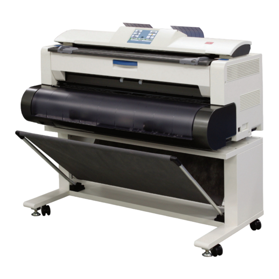
1. 5 Appearance 1. 5. 1 Front view Name Function Main Switch You can turn on/off this machine. Original Guides Feed the original under the Scanner Unit along the Original Guides. User Interface This is a Touch Screen, and many kinds of user operation are available. -
Page 15: Rear View
1. 5. 2 Rear view 7: behind Name Function Toner Cover Open here to access toner supply system. Original Guide These trays catch the original ejected from the Scanner Unit. LAN Port Connect the LAN Cable to connect this machine to the network. -
Page 16: Specifications For The Scan Original
1. 6 Specifications for the Scan Original A scan original must satisfy the following specifications. Thickness 0.05mm to 1.6mm Width 279.4mm to 914.4mm Length 210mm to 6,000mm (If an original is thicker than 0.65mm, its image quality is not guaranteed even it is transported.) Do not scan the following kinds of originals. - Page 17 Not square Metal or fabric material Metal Fabric Rough surface (Carbon paper for example) Rough surface Clipped or stapled Clipped Stapled 1-12 Chapter 1 Before Use...
- Page 18 The following kinds of originals can be read with using a carrier sheet. Image quality or the reliability of paper feeding for them is not guaranteed. Patched Punched 1-13 Chapter 1 Before Use...
-
Page 19: Specifications For The Printing Paper
1. 7 Specifications for the Printing Paper 1. 7. 1 Papers not available to use Do not use the following kinds of printing paper. Doing so may damage the print engine. Excessively curled (a diameter of 50 mm or less) Folded Creased Torn... -
Page 20: Keeping The Paper In The Custody
Pre-printed Extremely slippery Extremely sticky Extremely thin and soft OHP Film CAUTION Do not use the paper with staple, or do not use such conductive paper as aluminum foil and carbon paper. The above may result in a danger of fire. NOTE (1) Print image may become light if printed on a rough surface of the paper. -
Page 21: Treatment Against Environmental Condition
1. 7. 3 Treatment against environmental condition Take a necessary treatment according to the environmental condition as shown below. Humidity(%) Possible problem Necessary treatment “Void of image”, “crease of paper” and 1. Install an humidifier in the room, and other problems occurs when you print humidify the room air. - Page 22 Chapter 2 Basic Operation page 2. 1 Turning on 2- 2 2. 2 Turning off 2- 4 2. 3 Replacing Roll Media 2- 5 2. 4 Initial Cut 2- 9 2. 5 Toner Supply 2-10 2. 6 Cut Sheet Media 2-13 2.
-
Page 23: Turning On
2. 1 Turning on 1. Ensure that the machine is plugged into a dedicated wall outlet. WARNING (1) Do not handle the Power Plug with wet hands, or you may receive an electrical shock. (2) Make sure to earth the machine for safety. (3) Do not plug the printer into a multi-wiring connector in which other devices are plugged. - Page 24 3. The User Interface (UI) starts operating, and displays the following Copy Mode Screen in one minute. The Ready Indicator on Copy Mode Screen will flash during warming up. Ready Indicator The UI screen may vary depending on your system configuration. (Shown with available options) 4.
-
Page 25: Turning Off
2. 2 Turning off 1. There is a Power Switch on the right side of the machine. Press its “ ” side to turn off the machine. Power Switch Press “ ” side. CAUTION This machine print engine and UI appear to be shut down when you turn off the machine. However, the controller PC embedded inside the machine is still operating and will shutdown in approximately two minutes after Power Switch operation. -
Page 26: Replacing Roll Media
2. 3 Replacing Roll Media NOTE A media mis-feed tends to occur just before out of a roll media. 1. Open Roll Deck Cover (1). Holding both Flanges (2), lift and remove a roll media or an empty roll core (3). 2. - Page 27 4. Insert each Flange (2) into both ends of the roll media core to be installed. NOTE (1) Fully insert Flange into the roll media core so that the inside rim of Flange evenly touches the side face of the roll media. Inside Rim Inside Rim Correct: Fully inserted...
- Page 28 6. Lift the roll media by holding both Flanges. Lower Flanges onto Slide Guides (5) in Roll Deck. NOTE (1) Be careful of the winding direction of the roll media. This direction (2) The outside rim of Flange (2) should fit into the groove on the Slide Guide. Otherwise the roll media may fall in Roll Deck or result in an incorrect media feeding.
- Page 29 7. Rotate the roll media in the arrow direction and insert the leading edge of the roll media to the media path until it touches the feeding rollers (6). After that, the leading edge will automatically go into the roll media’s wait position. This is called “Auto Media Loading”.
-
Page 30: Initial Cut
2. 4 Initial Cut Reference (1) Initial Cut is a function to trim the roll media with its leading edge cut off. (2) Initial Cut becomes available while the printer is ready. 1. Open the Manual Feeder Table (1). 2. Press the green button (2) on the right. 3. -
Page 31: Toner Supply
2. 5 Toner Supply When the UI screen shows “Adding Toner”, follow the instruction to install a genuine Toner Cartridge. 1. Open the Toner Hatch (1) on the rear top. You do not have to remove the Original Guide. 2. Shake the Toner Bottle (2) several times to loosen the toner. - Page 32 3. Put the dent area (3) under the holder (4) to firmly seat the bottom plate of the Toner Bottle (2) to the toner supply position. from front from right from front 2-11 Chapter 2 Basic Operation...
- Page 33 4. With pressing down the Toner Bottle (2), slide the green lever (5) to the arrow direction until it stops. When it stops, wait 10 seconds as it is. from right NOTE Gently press down the Toner Bottle. Pressing too much makes the lever (5) much heavier. 5.
- Page 34 6. Close the Toner Hatch (1). 7. Press [OK] button on the UI screen. 2-13 Chapter 2 Basic Operation...
-
Page 35: Cut Sheet Media
2. 6 Cut Sheet Media There are several size markings on the table of Bypass Feeder which indicate possible feed positions. Place the cut sheet on the table between its concerning size markings then insert it into the Bypass Feeder. When the leading edge touches the feeding roller, the printer automatically carries and sets the paper at the proper position. -
Page 36: Copying
2. 7 Copying 1. There are several size markings on Original Table which indicate possible feed positions. Line up Original Guides (1) with the proper markings according to the original width. 2. Place the original on the Original Table with face up. Then insert it under the Scanner Unit along with Original Guides. -
Page 37: Emergency Stop Of Scan Or Copy
2. 8 Emergency Stop of Scan or Copy 1. If necessary, press the Emergency Stop Button (1) on the Scanner Unit to immediately stop the original while making a copy or scan. Pressing the button stops the current reading a document immediately. The current printing is stopped as well and is ejected. -
Page 38: Canceling Sleep Mode
2. 9 Canceling Sleep Mode The machine has two Sleep Modes to reduce the power consumption. The machine will enter Sleep Mode after a certain period of inactivity. In the default setting; Warm Sleep Mode will start after a 15 minute of inactivity in order to reduce the power supply for Fuser Unit. - Page 39 Chapter 3 Error Correction page 3. 1 Mis-feed Error 3- 2 3. 1. 1 J-0103 Roll Deck section 3- 3 3. 1. 2 J-0203 Manual Feeder section 3- 5 3. 1. 3 J-0104 / 0204 Media Feed section 1 3- 6 3.
-
Page 40: Mis-Feed Error
3. 1 Mis-feed Error If a jam occurs, the UI screen will show its location and the corresponding code “J-****” (if any). Please refer to the following figure to check the jam location. (Mis-feed Codes are described on the later pages.) Fuser Section J-0106 / 0206 Feed Section 2... -
Page 41: 0103 Roll Deck Section
3. 1. 1 J-0103 Roll Deck section Remove a mis-feed media in the Roll Deck if the UI screen will show J-0103. J-0103 1. Open the Roll Deck Cover. Rewind the roll onto the media core. 2. Rotate the roll media in the arrow direction and insert the leading edge of the roll media to the media path until it touches the feeding rollers (1). - Page 42 Reference If your roll media’s end is not fixed to the core (by glue or a tape), a small portion of the media may remain in the media path of the Roll Deck at a roll empty. The printer does not show any mis-feed error code against the portion.
-
Page 43: 0203 Manual Feeder Section
3. 1. 2 J-0203 Manu l Feeder section Remove a mis-feed media in the Manual Feeder if the UI screen will show J-0203. J-0203 1. Pull out the mis-feed cut sheet from the Manual Feeder. NOTE The mis-feed cut sheet should be replaced with a new one if its leading edge has a torn or fold. -
Page 44: J-0104 / 0204 Media Feed Section
3. 1. 3 J-0104 / 0204 Media Feeder section 1 Remove a mis-feed media in the Media Feeder section 1 if the UI screen will show J-0104 or 0204. J-0104 or J-0204 1. Press down the blue levers (1) on both sides to unlock and open the Upper Unit. 2. - Page 45 3. Put your hands on the rear rim of the scanner unit just as you hold the Upper Unit. Push the entire unit down to the arrow direction. Hold here Hold here Chapter 3 Error Correction...
-
Page 46: J-0105 / 0205 Media Feed Section
3. 1. 4 J-0105 / 0205 Media Feeder section 2 Remove a mis-feed media in the Media Feeder section 2 if the UI screen will show J-0105 or 0205. J-0105 or J-0205 1. Press down the blue levers (1) on both sides to unlock and open the Upper Unit. 2. - Page 47 3. Put your hands on the rear rim of the scanner unit just as you hold the Upper Unit. Push the entire unit down to the arrow direction. Hold here Hold here Chapter 3 Error Correction...
-
Page 48: 0106 / 0206 Fuser Section
3. 1. 5 J-0106 / 0206 Fuser section Remove a mis-feed media in the Fuser section if the UI screen will show J-0106 or 0206. J-0106 or J-0206 1. Hold the blue handle (1) and open the Exit Cover (2). 2. - Page 49 3. Press down the blue levers (3) on both sides to unlock and open the Upper Unit. 4. Remove the mis-feed media. 5. Close the Exit Door. 3-11 Chapter 3 Error Correction...
- Page 50 6. Put your hands on the rear rim of the scanner unit just as you hold the Upper Unit. Push the entire unit down to the arrow direction. Hold here Hold here 3-12 Chapter 3 Error Correction...
-
Page 51: 1300 / 1400 Door Open While Printing
3. 1. 6 J-1300 / 1400 Door Open while printing If the Exit Cover or the Upper Unit is open while the printer is processing a print job, the UI screen will show J-1300 (Exit Cover) / J-1400 (Upper Unit). For clearing J-1400, please start on the step 3. - Page 52 4. Remove the mis-feed media. If the mis-feed media does not exist, go to the next step. 5. Close the Exit Door. 6. Put your hands on the rear rim of the scanner unit just as you hold the Upper Unit. Push the entire unit down to the arrow direction.
- Page 53 7. Open the Roll Deck Cover. Rewind the roll onto the media core. 8. Rotate the roll media in the arrow direction and insert the leading edge of the roll media to the media path until it touches the feeding rollers (4). After that, the leading edge will automatically go into the roll media’s wait position.
-
Page 54: Original Jam
3. 1. 7 Original Jam If an original is mis-fed while scanning, the UI screen shows “Original Jam”. Follow the instruction below to remove the mis-fed original. 1. On both sides, pull the levers (1) under the scanner cover to open the Scanner Unit until it locks. 2. -
Page 55: Other Operator Call Error
3. 2 Other Operator Call Error 3. 2. 1 Roll Replacement When the printer is running out of a loaded roll media, the UI Screen will display “Roll Replacement” sign. If there is no suitable roll media required for the current print job, the UI Screen will display “Roll Replacement”... -
Page 56: Service Call Error
3. 3 Service Call Error In case the following Error Codes for a serious failure appear in the screen; PLEASE CALL YOUR TRAINED SERVICE PERSONNEL TO RESOLVE THE ERRORS. No operation should be done by the customer. Error Code E - 000 E - 001 E - 002 E - 003... - Page 57 Chapter 4 Maintenance page 4. 1 Cleaning 4- 2 4. 1. 1 Scanner Unit 4- 2 4. 1. 2 Touch Screen 4- 4 Chapter 4 Maintenance...
- Page 58 4. 1 Cleaning 4. 1. 1 Scanner Unit It is recommended to clean each Scan Glass, Feeding Rollers and Guide Plates as the scan/copy image may become defective if these parts are dirty. 1. Turn off the machine. 2. Press the levers (1) up to unlock the Scanner Unit. Open the Scanner Unit. 3.
- Page 59 4. Wipe the Feed Rollers (4: gray), Press Rollers (5: white) and the inside surface with a soft dry cloth. 5. Gently press Scanner Unit down and firmly close it. NOTE Press down Scanner Unit on both side to close it. Do not close it by pressing only one side down.
- Page 60 4. 1. 2 Touch Screen 1. Wipe the Touch Screen with a dry cloth. NOTE Do not use water, alcohol, organic solvent and glass cleaner for the cleaning. Chapter 4 Maintenance...
- Page 61 First edition 2011.5 5J0KMEN000...