
Related Manuals for Gigabyte GA-6LXSV


Summary of Contents for Gigabyte GA-6LXSV
- Page 1 GA-6LXSV LGA1150 socket motherboard for Intel E3 series processors ® User's Manual Rev. 1001...
- Page 2 GIGABYTE's prior written permission. Documentation Classifications In order to assist in the use of this product, GIGABYTE provides the following types of documentations: For detailed product information, carefully read the User's Manual.
-
Page 3: Table Of Contents
Table of Contents Box Contents ........................5 GA-6LXSV Motherboard Layout ..................6 Chapter 1 Hardware Installation ..................9 Installation Precautions ..................9 1-2 Product Specifications ..................10 Installing the CPU and CPU Cooler ............... 12 1-3-1 Installing the CPU ....................12 1-3-2 Installing the CPU Cooler ..................14 Installing the Memory .................. - Page 4 2-3-2-2 USB Configuration ....................74 2-3-3 Intel Server Platform Services ................75 Security Menu ....................76 2-4-1 Secure Boot menu ....................77 2-4-1-1 Image Execution Policy ..................78 2-4-1-2 Key Management ....................79 Server Management Menu ................81 2-5-1 BMC LAN Configuration ..................82 2-5-2 Gbt BMC Function ....................83 2-5-3 View FRU Information ....................84 2-5-4...
-
Page 5: Box Contents
Box Contents GA-6LXSV motherboard Driver CD Two SATA cables I/O Shield • The box contents above are for reference only and the actual items shall depend on the product package you obtain. The box contents are subject to change without notice. -
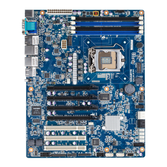
Page 6: Ga-6Lxsv Motherboard Layout
GA-6LXSV Motherboard Layout 44 45 48 49 51 52 - 6 -... - Page 7 Item Code Description ID_SW1 ID Switch button MLAN1 BMC Management LAN port LAN1 port (top) / USB 3.0 ports USB3_LAN1 (bottom) LAN2 port (top) / USB 3.0 ports USB3_LAN2 (bottom) LAN_3_4 LAN ports COM1_VGA1 Serial port (top) / VGA port (bottom) USB 2.0 ports (top)/PS/2 connector KB_USB1 (buttom)
- Page 8 SATA_DOM1 SATA port 0 DOM support jumper. J_HDA_SDO1 ME recovery jumper Intel C224 Chipest F_USB1 USB 2.0 header BP_1 Back plane board header SGPIO SGPIO header LAN3 Active LED (Right) LAN3/LAN4 LAN4 Active LED (Left) FP_1 Front panel header COM2 Serial port cable connector PCI_1 PCI 32bit/33MHz slot...
-
Page 9: Chapter 1 Hardware Installation
Chapter 1 Hardware Installation Installation Precautions The motherboard contains numerous delicate electronic circuits and components which can become damaged as a result of electrostatic discharge (ESD). Prior to installation, carefully read the user's manual and follow these procedures: • Prior to installation, do not remove or break motherboard S/N (Serial Number) sticker or warranty sticker provided by your dealer. -
Page 10: Product Specifications
1-2 Product Specifications Support for Intel Xeon E3-1200 family processors in the LGA1150 package Š ® ® L3 cache varies with CPU Š Chipset Intel C224 PCH Š ® Memory 4 x 1.5V DDR3 DIMM sockets supporting up to 32 GB of system memory Š... - Page 11 * If you want to active the rear I/O USB 3.0 ports in Linux RedHat operating system, please update the kernel to the version 2.6.37. GIGABYTE reserves the right to make any changes to the product specifications and product-related information without prior notice.
-
Page 12: Installing The Cpu And Cpu Cooler
Read the following guidelines before you begin to install the CPU: • Make sure that the motherboard supports the CPU. (Go to GIGABYTE's website for the latest CPU support list.) • Always turn off the computer and unplug the power cord from the power outlet before installing the CPU to prevent hardware damage. - Page 13 B. Follow the steps below to correctly install the CPU into the motherboard CPU socket. Before installing the CPU, make sure to turn off the computer and unplug the power cord from the power outlet power plug to prevent any damage to prevent damage to the CPU. Step 1: Step 2: Gently press the CPU socket lever handle down...
-
Page 14: Installing The Cpu Cooler
1-3-2 Installing the CPU Cooler Follow the steps below to correctly install the CPU cooler on the motherboard. (The following procedure uses Intel boxed cooler as the example cooler.) ® Male Push Direction of the Arrow Sign on The Top the Male Push of Female Push Pin... -
Page 15: Installing The Memory
Installing the Memory Read the following guidelines before you begin to install the memory: • Make sure that the motherboard supports the memory. It is recommended that memory of the same capacity, brand, speed, and chips be used. • Always turn off the computer and unplug the power cord from the power outlet before installing the memory to prevent hardware damage. -
Page 16: Installing A Memory
1-4-2 Installing a Memory Before installing a memory module, make sure to turn off the computer and unplug the power cord from the power outlet to prevent damage to the memory module. Be sure to install DDR3 DIMMs on this motherboard. Installation Step: Step 1. -
Page 17: Back Panel Connectors
Back Panel Connectors USB 2.0/1.1 Port The USB port supports the USB 2.0/1.1 specification. Use this port for USB devices such as a USB keyboard/mouse, USB printer, USB flash drive and etc. PS/2 Keyboard/Mouse Port Coonnect a PS/2 keyboard or mouse to this port. Serial Port Connects to serial-based mouse or data processing devices. -
Page 18: Hardware Installation
Link MLAN Speed LED: Link/Activity LED: Speed LED Activity LED State Description State Description Green On 100 Mbps data rate Link bet ween system and net work or no Green Blink 10 Mbps or 100 Mbps access data rate Blinking Data transmission or receiving is occurring 10/100 LAN Port 10 Mbps data rate No data transmission or receiving is occurring... -
Page 19: Internal Connectors
Internal Connectors SGPIO IPMB1 CPU0_FAN1 (CPU Fan) BMC_LED2 SYS_FAN1 (System Fan) LAN3 SYS_FAN2 (System Fan) LAN4 SYS_FAN3 (System Fan) SYS_FAN4 (System Fan) PMBUS_CN_1 J_CLRCMOS SATA0/1 J_MEUPDATE SATA23 J_HDA_SDO1 SATA45 J_PASSWORD FP_1 J_BIOSRCVR F_USB3_1 J_S3MASK F_USB1 PMBUS_SEL1 COM2 SATA_DOM1 TPM_MEZZ1 SATA_DOM2 Read the following guidelines before connecting external devices: • First make sure your devices are compliant with the connectors you wish to connect. - Page 20 1/2) P1/P2 (2x12 Main Power Connector and 2x4 12V Power Connector) With the use of the power connector, the power supply can supply enough stable power to all the components on the motherboard. Before connecting the power connector, first make sure the power supply is turned off and all devices are properly installed.
- Page 21 3/4/5/6/7) CPU0_FAN1/SYS_FAN1/SYS_FAN2/SYS_FAN3/SYS_FAN4 (CPU Fan/System Fan Headers) The motherboard has a 4-pin CPU fan header (CPU0_FAN1), and four 4-pin (SYS_FAN1/SYS_FAN2/ SYS_FAN3/SYS_FAN4) system fan headers. Most fan headers possess a foolproof insertion design. When connecting a fan cable, be sure to connect it in the correct orientation (the black connector wire is the ground wire).
- Page 22 PORT 9/10) SATA0/SATA1/SATA23 (SATA 6Gb/s Connectors) The SATA connectors conform to SATA 6Gb/s standard and are compatible with SATA 3Gb/s and 1.5Gb/s standard. Each SATA connector supports a single SATA device. DEBUG PORT When SATA_DOM0/1 jumper DEBUG are set to 2-3 pin: PORT Pin No.
- Page 23 12) FP_1 (Front Panel Header) Connect the power switch, reset switch, chassis intrusion switch/sensor and system status indicator on the chassis to this header according to the pin assignments below. Note the positive and negative pins before connecting the cables. 23 24 Pin No.
- Page 24 13) F_USB3_1 (USB 3.0 Header) The headers conform to USB 3.0 specification. Each USB header can provide two USB ports via an optional USB bracket. For purchasing the optional USB bracket, please contact the local dealer. Pin No. Definition Power IntA_P1_SSRX- IntA_P1_SSRX+ IntA_P1_SSTX-...
- Page 25 15) COM2 (Serial Port Header) The COM header can provide one serial port via an optional COM port cable. For purchasing the optional COM port cable, please contact the local dealer. Pin No. Definition NDCD- NDSR- NSIN NRST- NSOUT NCTS- NDTR- No Pin 16) TPM_MEZZ1 (TPM Module connector)
- Page 26 17) SGPIO (SATA SGPIO Header) SGPIO is stands for Serial General Purpose Input/Output which is a 4-signal (or 4-wire) bus used between a Host Bus Adapter (HBA) and a backplane. Out of the 4 signals, 3 are driven by the HBA and 1 is driven by the backplane.
- Page 27 19) BMC_LED2 (BMC Firmware Readiness LED) State Description BMC firmware is initial Blinking BMC firmware is ready System is powered off 20/21) LAN3/LAN4(LAN3/LAN4 link/active LED Headers) LAN4 LAN3 Pin No. Definition 3.3V Active - 27 - Hardware Installation...
- Page 28 22) JP2 (Case open intrusion header) Open: Active chassis intrustion alert. Closed: Normal operation. 23) BAT (Battery) The battery provides power to keep the values (such as BIOS configurations, date, and time information) in the CMOS when the computer is turned off. Replace the battery when the battery voltage drops to a low level, or the CMOS values may not be accurate or may be lost.
-
Page 29: Clearing Cmos Jumper
24) J_CLRCMOS (Clearing CMOS Jumper) Use this jumper to clear the CMOS values (e.g. date information and BIOS configurations) and reset the CMOS values to factory defaults. To clear the CMOS values, place a jumper cap on the two pins to temporarily short the two pins or use a metal object like a screwdriver to touch the two pins for a few seconds. - Page 30 27) J_PASSWORD (Clearing Supervisor Password Jumper) 1-2 Close: Normal operation. (Default setting) 2-3 Close: Clear supervisor password. 28) J_BIOSRVCR (BIOS Recovery Jumper) 1-2 Close: Normal operation. (Default setting) 2-3 Close: BIOS recovery mode. Hardware Installation - 30 -...
- Page 31 29) J_S3MASK (S3 Power On Select Jumper) 1-2 Close: Stop an initial power on when BMC is not ready. 2-3 Close: Keep initial power on. (Default setting) 30) PMBUS_SEL1 (PMBus Power Select Jumper) 1-2 Close: PMBus connects to PCH. 2-3 Close: PMBus connects to BMC. (Default setting) - 31 - Hardware Installation...
- Page 32 31/32) SATA_DOM1/SATA_DOM2 (SATA port 0 and port 1 DOM Jumpers) CAUTION! • If the SATA DOM power is supplied by the motherboard, set the jumper to pin 1-2. • If the SATA DOM power is supplied by external power, set the jumper to pin 2-3. •...
-
Page 33: Chapter 2 Bios Setup
Chapter 2 BIOS Setup BIOS (Basic Input and Output System) records hardware parameters of the system in the EFI on the motherboard. Its major functions include conducting the Power-On Self-Test (POST) during system startup, saving system parameters and loading operating system, etc. BIOS includes a BIOS Setup program that allows the user to modify basic system configuration settings or to activate certain system features. - Page 34 Main This setup page includes all the items in standard compatible BIOS. Advanced This setup page includes all the items of AMI BIOS special enhanced features. (ex: Auto detect fan and temperature status, automatically configure hard disk parameters.) ...
-
Page 35: The Main Menu
The Main Menu Once you enter the BIOS Setup program, the Main Menu (as shown below) appears on the screen. Use arrow keys to move among the items and press <Enter> to accept or enter other sub-menu. Main Menu Help The on-screen description of a highlighted setup option is displayed on the bottom line of the Main Menu. -
Page 36: Memory Frequency
BIOS Information BIOS Version Display version number of the BIOS setup utility. BIOS Build Date and Time Displays the date and time when the BIOS setup utility was created. BMC Information BMC Firmware Version Display version number of the BMC setup utility. SDR Version Display the SDR version of the BMC setup utility. -
Page 37: Advanced Menu
Advanced Menu The Advanced menu display submenu options for configuring the function of various hardware components. Select a submenu item, then press Enter to access the related submenu screen. - 37 - BIOS Setup... -
Page 38: Acpi Configuration
2-2-1 ACPI Configuration ACPI Settings ACPI Sleep State Select the highest ACPI sleep state the system will enter, when the suspend button is pressed. Options available: Suspend Disabled/S1 only (CPU Stop Clock)/S3 only (Suspend to RAM)/ Both S1 and S3 available for OS to choose from. Default setting is S3 only (Suspend to RAM). BIOS Setup - 38 -... -
Page 39: Trusted Computing (Optional)
2-2-2 Trusted Computing (Optional) Configuration Security Device Support Select Enabled to activate TPM support feature. Options available: Enabled/Disabled. Default setting is Enabled. Current Status Information Display current TPM status information. - 39 - BIOS Setup... -
Page 40: Pci Subsystem Settings
2-2-3 PCI Subsystem Settings PCI Express Slot #1/2/3/4 I/O ROM When enabled, This setting will initialize the device expansion ROM for the related PCI-E slot. Options available: Enabled/Disabled. Default setting is Enabled. PCI Slot #1/2/3 I/O ROM Enable/Disable PCI slot #1/#2/#3 devices and initialize device expansion ROM. Options available: Enabled/Disabled. -
Page 41: Perr Generation
PERR Generation When this item is set to enabled, PCI bus parity error (PERR) is generated and is routed to NMI. Options available: Enabled/Disabled. Default setting is Disabled. SERR Generation When this item is set to enabled, PCI bus system error (SERR) is generated and is routed to NMI. Options available: Enabled/Disabled. -
Page 42: Pci Express Settings
2-2-3-1 PCI Express Settings PCI Express Device Register Settings Relaxed Ordering Enable/DIsable PCI Express Device Relaxed Ordering feature. Options available: Enabled/Disabled. Default setting is Disabled. Extended Tag Wnen this feature is enabled, the system will allow device to use 8-bit Tag field as a requester. Options available: Enabled/Disabled. - Page 43 Link Training Retry Define the number of Retry Attempts software wil take to retrain the link if previous training attempt was unsuccessful. Press <+> / <-> keys to increase or decrease the desired values. Link Training Timeout (us) Define the number of Microseconds software will wait before polling 'Link Training' bit in Link Status register.
- Page 44 2-2-4 CPU Configuration BIOS Setup - 44 -...
-
Page 45: Cpu Configuration
CPU Configuration CPU Type/ Signature / Microcode Patch / Max CPU Speed / Min CPU Speed / Processor Cores / Intel HT Technology / Intel VT-x Technology / Intel SMX Technology Displays the technical specifications for the installed processor. 64-bit Display the supported information of installed CPU. EIST Technology Display Intel EIST Technology function support information. -
Page 46: Hardware Prefetcher
Overclocking lock Enable/Disable processor overcllocking lock function. Options available: Enabled/Disabled. Default setting is Disabled. Limit CPUID Maximum When enabled, the processor will limit the maximum CPUID input values to 03h when queried, even if the processor suppports a higher CPUID input value. When disabled, the processor will return the actual maximum CPUID input value of the processor when queried. - Page 47 The larger value in MSR_ENERGY_PERFORMANCE_BIAS register, CPU will save more power but lose more performance. Note: This register will be changed by OS too if OS support it like Windows 2008 or newer Linux. Options available: Performance : Write value 0 into MSR_ENERGY_PERFORMANCE_BIAS Balanced Performance: Write value 7 into MSR_ENERGY_PERFORMANCE_BIAS Balanced Energy: Write value 11 into MSR_ENERGY_PERFORMANCE_BIAS Energy Efficient: Write value 15 into MSR_ENERGY_PERFORMANCE_BIAS...
- Page 48 ACPI T State Enable/Disable ACPI T state support. Options available: Enabled/Disabled. Default setting is Disabled. CPU DTS Enable/Disable CPU DTS support. Options available: Enabled/Disabled. Default setting is Disabled. BIOS Setup - 48 -...
-
Page 49: Sata Configuration
2-2-5 SATA Configuration - 49 - BIOS Setup... -
Page 50: Aggressive Lpm Support
SATA Controller(s) Enable/Disable the SATA controller. Options available: Enabled/Disabled. Default setting is Enabled. SATA Mode Selection Select the on chip SATA type. RAID Mode: When set to RAID, the SATA controllerenables both its RAID and AHCI functions. You will be allows access the RAID setup utility at boot time. AHCI Mode: When set to AHCI,the SATA controller enables its AHCI functionality. -
Page 51: Software Feature Mask Configuration
2-2-5-1 Software Feature Mask Configuration RAID 0 Enable/Disable RAID 0 feature. Options available: Enabled/Disabled. Default setting is Enabled. RAID 1 Enable/Disable RAID 1 feature. Options available: Enabled/Disabled. Default setting is Enabled. RAID 10 Enable/Disable RAID 10 feature. Options available: Enabled/Disabled. Default setting is Enabled. RAID 5 Enable/Disable RAID 5 feature. - Page 52 HDD Unlock When this item is enabled, the HDD password unlock in the OS is enabled. Options available: Enabled/Disabled. Default setting is Enabled. LED Locate When this item is enabled, the LED/SGPIO hardware is attached and ping to locate feature is enabled on the OS.
-
Page 53: Info Report Configuration
2-2-6 Info Report Configuration Info Report Configuration Post Report Enable/Disable Post Report support. Options available: Enabled/Disabled. Default setting is Disabled. Delay Time Press <+> / <-> keys to increase or decrease the desired values. Error Message Report Info Error Message Enable/Disable Info Error Message support. Options available: Enabled/Disabled. -
Page 54: Usb Configuration
2-2-7 USB Configuration Legacy USB Support Enables or disables support for legacy USB devices. Options available: Auto/Enabled/Disabled. Default setting is Enabled. USB30. Support Enables/Disable USB3.0 (XHCI) controller support. Options available: Enabled/Disabled. Default setting is Enabled. XHCI Hand-off Enable/Disable XHCI (USB 3.0) Hand-off support. Options available: Enabled/Disabled. -
Page 55: Super Io Configuration
2-2-8 Super IO Configuration - 55 - BIOS Setup... -
Page 56: Serial Port
Super IO Chip Display the model name of Super IO chip. Serial Port 0/1 Configuration Serial Port When enabled allows you to configure the serial port settings. When set to Disabled, displays no configuration for the serial port. Options available: Enabled/Disabled. Default setting is Enabled. Device Settings Display the Serial Port 0/1 base I/O addressand IRQ. -
Page 57: Serial Port Console Redirection
2-2-9 Serial Port Console Redirection - 57 - BIOS Setup... -
Page 58: Console Redirection Settings
COM1/COM2/Serial Port for Out-of Band Management / Windows Emergency Management Service (EMS) Console Redirection (Note) Select whether to enable console redirection for specified device. Console redirection enables users to manage the system from a remote location. Options available: Enabled/Disabled. Default setting is Disabled. Console Redirection Settings Terminal Type Select a terminal type to be used for console redirection. - Page 59 Legacy OS Redirection Resolution (Note) On Legacy OS, the number of Rows and Columns supported redirection. Options available: 80x24/80X25. Putty KeyPad (Note) Select function FunctionKey and KeyPad on Putty. Options available: VT100/LINUX/XTERMR6/SCO/ESCN/VT400. Redirection After BIOS POST (Note) This option allows user to enable console redirection after O.S has loaded. Options available: Always Enable/Boot Loader.
-
Page 60: Network Stack
2-2-10 Network Stack Network stack Enable/Disable UEFI network stack. Options available: Enabled/DIsabled. Default setting is Disabled. BIOS Setup - 60 -... -
Page 61: Iscsi Configuration
2-2-11 iSCSI Configuration iSCSI Initiator Name Add an Attempts Press [Enter] for configuration of advanced items. Delete Attempts Press [Enter] for configuration of advanced items. Change Attempt Order Press [Enter] for configuration of advanced items. - 61 - BIOS Setup... -
Page 62: Intel (R) I210 Gigabit Network Connection
2-2-12 Intel (R) I210 Gigabit Network Connection BIOS Setup - 62 -... - Page 63 PORT CONFIGURATION MENU NIC Configuration Link Speed Change link speed duplex for current port. Options available: AutoNeg/10Mbps Half/10Mbps Half/10Mbps Half/100Mbps Full. Default setting is AutoNeg. Wake On LAN Enable/Disable Wake On LAN feature. Options available: Enabled/DIsabled. Default setting is Enabled. Blink LEDs (range 0-15 seconds) Blink LEDs for the specified duration (up to 15 seconds).
-
Page 64: Chipset Menu
Chipset Menu The Chipset menu display submenu options for configuring the function of North Bridge and South Bridge. Select a submenu item, then press Enter to access the related submenu screen. BIOS Setup - 64 -... -
Page 65: System Agent (Sa)Configuration
2-3-1 System Agent (SA)Configuration System Agent Bridge Name Display the System Agent (SA) Bridge Name. System Agent RC Version Display the version number of System Agent RC. VT-d Capability Display the VT-d support information. VT-d Enable/Disable Intel Virtualization Technology for Directed I/O (VT-d) feature. Options available: Enabled/DIsabled. -
Page 66: Graphic Configuration
2-3-1-1 Graphic Configuration Graphic Configuration Primary Display Device Configure the Primary display device. Options available: Auto//PCIE Slot 1/PCIE Slot 2/PCIE Slot 3/PCIE Slot 4/Onboard Vga. Default setting is Auto. BIOS Setup - 66 -... -
Page 67: Nb Pcie Configuration
2-3-1-2 NB PCIe Configuration NB PCIe Configuration PEG0 Display PEG0 configuration information. PEG0 - Gen X Configure PEG0 B0:D1:F0 Gen1-Gen3. Options available: Auto/Gen1/Gen2/Gen3. Default setting is Auto. PEG1 Display PEG1 configuration information. PEG1 - Gen X Configure PEG1 B0:D1:F1 Gen1-Gen3. Options available: Auto/Gen1/Gen2/Gen3. Default setting is Auto. PEG2 Display PEG2 configuration information. - Page 68 PEG0 De-emphasis Control PEG0:Configure the De-emphasis control on PEG. Options available: Options available: -6 dB/-3.5 dB. Default setting is -3.5 dB. PEG1 De-emphasis Control PEG1:Configure the De-emphasis control on PEG. Options available: Options available: -6 dB/-3.5 dB. Default setting is -3.5 dB. PEG2 De-emphasis Control PEG2:Configure the De-emphasis control on PEG.
-
Page 69: Memory Configuration
2-3-1-3 Memory Configuration Memory Information Memory RC Version Display version number of installed memeory. Memory Frequency Display the frequency information of installed memory. Total Memory Determines how much total memory is present during the POST. Memory Voltage Display the voltage information of installed memory. DIMM Information: DDR3_P0_A0/DDR3_P0_A1/DDR3_P0_B0/DDR3_P0_B1 Status The size of memory installed on each of the DDR3 slots. - Page 70 Memory Frequency Limiter Maximum Memory Frequency Selections in Mhz. Options available: Auto/1067/1333/1600/1867/2133/2400/2667. Default setting is Auto. Max TOLUD Maximum Value of TOLUD. Dynamic assignment would adjust TOLUD automatically based on largest MMIO length of installed graphic controller. Options available: Dynamic/3.5 GB/3.25 GB/3 GB/2.75 GB/2.5 GB/2.25 GB/2 GB/1.75 GB/1.5 GB/ 1.25 GB/1 GB.
-
Page 71: Pch-Io Configuration
2-3-2 PCH-IO Configuration Intel PCH RC Version/Intel PCH SKU/Intel PCH Rev ID Information Displays the RC version, SKU and Reverison ID information of PCH. PCI Express Configuration Press [Enter] for configuration of advanced items. USB Configuration Press [Enter] for configuration of advanced items. DeepSx Power Policies Configure the DeepSx Mode configuration. - Page 72 Restore AC Power Loss This option provides user to set the mode of operation if an AC / power loss occurs. Power On: System power state when AC cord is re-plugged. Power Off: Do not power on system when AC power is back. Last State: Set system to the last sate when AC power is removed.
-
Page 73: Pci Express Configuration
2-3-2-1 PCI Express Configuration PCI Express Clock Gating Enable/Disable PCI Express Clock Gating for each root port. Options available: Enabled/Disabled. Default setting is Enabled. DMI Link ASPM Control The control of Active State Power Management on both NB side and SB side of the DMI Link. Options available: Enabled/Disabled. -
Page 74: Usb Configuration
2-3-2-2 USB Configuration USB Configuration USB Precondition Precondition work on USB host controller and root ports for faster enumeration. Options available: Enabled/Disabled. Default setting is Disabled. XHCI Mode Mode of operation of xHCI controller. Options available: Smart Auto/Auto/Enabled/Disabled/Manual. Default setting is Smart Auto. BTCG Options available: Enabled/Disabled. -
Page 75: Intel Server Platform Services
2-3-3 Intel Server Platform Services Intel Server Platform Services Enable/Disable Intel Server Platform Services Help. Options available: Enabled/Disabled. Default setting is Enabled. - 75 - BIOS Setup... -
Page 76: Security Menu
Security Menu The Security menu allows you to safeguard and protect the system from unauthorized use by setting up access passwords. There are two types of passwords that you can set: • Administrator Password Entering this password will allow the user to access and change all settings in the Setup Utility. •... -
Page 77: Secure Boot Menu
2-4-1 Secure Boot menu The Secure Boot Menu is applicable when your device is installed the Windows 8 operatin system. ® Platform Mode Display the System Platform Mode State. Secure Boot Display the status of Secure Boot. Secure Boot Control Enable/Disable Secure Boot function. -
Page 78: Image Execution Policy
2-4-1-1 Image Execution Policy Image Execution policy Internal FV Image Execution Policy per device path on Security Violation. Options available: Always Execute. Default setting is Always Execute. Option ROM Image Execution Policy per device path on Security Violation. Options available: Always Execute/Always Deny/Allow Execute/Defer Execute/ Deny Execute/ Query User. -
Page 79: Key Management
2-4-1-2 Key Management Key Management This item appears only when the Secure Boot Mode is set to Custom. Default Key Provisioning Factory Force the system to Setup Mode. This will clear all Secure Boot Variables such as Platform Key (PK), Key-exchange Key (KEK), Authorized Signature Database (db), and Forbidden Signaures Database (dbx). - Page 80 Set new KEK Press [Enter] to configure a new KEK. Append Var to KEK Press [Enter] to load additional KEK from a storage devices for an additional db and dbx management. Authorized Signature Database (DB) Display the status of Authorized Signature Database. Delete DB Press [Enter] to delete the db from your system.
-
Page 81: Server Management Menu
Server Management Menu BMC LAN Configuration BMC LAN Configuration. Press Enter to access the related submenu. Gbt BMC Function BMC related function configuration.Press Enter to access the related submenu. View FRU information The FRU information submenu is a simple display page for basic system ID information, as well as system product information. -
Page 82: Bmc Lan Configuration
2-5-1 BMC LAN Configuration Lan Channel 1 Configuration Source Select to configure LAN channel parameters statically or dynamically (DHCP). Do nothing option will not modify any BMC network parameters during BIOS phase. Options available: Static/Dynamic/Do Nothing. IP Address Display IP Address information. Subnet Mask Display Subnet Mask information. -
Page 83: Gbt Bmc Function
2-5-2 Gbt BMC Function Select NCSI and Dedicated LAN Switch NCSI and dedicated LAN and send KCS command. Options available: Mode2(NSCI)/ Mode1 (Dedicated). Default setting is Mode1 (Dedicated). - 83 - BIOS Setup... -
Page 84: View Fru Information
2-5-3 View FRU Information The FRU Information menu is a simple display page for basic system ID information, as well as System product information. Items on this window are non-configurable. BIOS Setup - 84 -... -
Page 85: System Event Log
2-5-4 System Event Log Enabling/Disabling Options Smbios Event Log Choose options to Enable/Disable logging of System boot event. Options available: Enabled/Disabled. Default setting is Disabled. Erasing Settings Erasing Event Log Choose options for erasing Smbios Event Log Erasing is done prior to any logging activation during reset. -
Page 86: Event Logs Menu
Event Logs Menu Change Smbios Event Log Settings Press [Enter] for configuration of advanced items. View Smbios Event Log Press [Enter] to view event logs. BIOS Setup - 86 -... -
Page 87: Change Smbios Event Log Settings
2-6-1 Change Smbios Event Log Settings Enabling/Disabling Options SEL Components Change this to enable or disable all features of System Event Logging during boot. Options available: Enabled/Disabled. Default setting is Enabled. Erasing Settings Erasing SEL Choose options for erasing Smbios Event Log Erasing is done prior to any logging activation during reset. - Page 88 METW Multiple Event Time Window: The number of minutes which must pass between duplicate log entries which utilize a multiple-event counter. The value ranges from 0 to 99 minutes. Press <+> / <-> keys to increase or decrease the desired values. Custom Options Log OEM Codes Enable/Disable the logging of EFI Status Codes as OEM Codes.
-
Page 89: View Smbios Event Log
2-6-2 View Smbios Event Log The Smbios Event Log is a display page of Smbios Event Log information. Items on this window are non- configurable. Press Enter to View Smbios Event Log - 89 - BIOS Setup... -
Page 90: Boot Menu
Boot Menu The Boot menu allows you to set the drive priority during system boot-up. BIOS setup will display an error message if the legacy drive(s) specified is not bootable. Boot Configuration Setup Prompt Timeout Number of seconds to wait for setup activation key. 65535(0xFFFF) means indefinite waiting." Press the numberic keys to input the desired value. - Page 91 Network Device BBS Priorities Press Enter to configure the boot priority. Hard Drive BBS Priorities Press Enter to configure the boot priority. CSM16 Parameters Press [Enter] for configuration of advanced items. CSM parameters Press [Enter] for configuration of advanced items. - 91 - BIOS Setup...
-
Page 92: Csm16 Parameters
2-7-1 CSM16 Parameters CSM16 Module Version Display CSM Module version information. Gate20 Active Upon Request: GA20 can be disabled using BIOS services. Always: Do not allow disabling GA20; this option is useful when any RT code is executed above 1MB. Options available: Upon Request/Always. -
Page 93: Csm Parameters
2-7-2 CSM Parameters CSM parameters Press Enter to configure the advanced items. CSM (Compatibility Support Module) Launch Enable/Disable Compatibility Support Module (CSM) launch. Options available: Enabled/Disabled. Default setting is Enabled. • The following five items appears and configurable when the Launch CSM is set to Enabled. •... - Page 94 Other PCI device ROM priority For PCI devices other than Network, Mass storage or Video device, defines which OpROM to launch. Options available: UEFI OpROM/Legacy OpROM. Default setting is UEFI OpROM. BIOS Setup - 94 -...
-
Page 95: Exit Menu
Exit Menu The Exit menu displays the various options to quit from the BIOS setup. Highlight any of the exit options then press Enter. Save Changes and Exit Saves changes made and close the BIOS setup. Options available: Yes/No. Discard Changes and Exit Discards changes made and close the BIOS setup. -
Page 96: Chapter 3 Appendix
Contravention will be prosecuted. We believe that the information contained herein was accurate in all respects at the time of printing. GIGABYTE cannot, however, assume any responsibility for errors or omissions in this text. Also note that the informa- tion in this document is subject to change without notice and should not be construed as a commitment by GIGABYTE. - Page 97 Finally, we suggest that you practice other environmentally friendly actions by understanding and using the energy-saving features of this product (where applicable), recycling the inner and outer packaging (including shipping containers) this product was delivered in, and by disposing of or recycling used batteries properly. With your help, we can reduce the amount of natural resources needed to produce electrical and electronic equipment, minimize the use of landfills for the disposal of "end of life"...