Panasonic KX MC6020 - Color Laser - All-in-One Service Manual
Optional lower input tray optional automatic duplex unit
Hide thumbs
Also See for KX MC6020 - Color Laser - All-in-One:
- Operating instructions manual (120 pages) ,
- Instrucciones de funcionamiento (120 pages) ,
- Specifications (2 pages)
Table of Contents
Advertisement
Quick Links
Advertisement
Table of Contents
Troubleshooting

Related Manuals for Panasonic KX MC6020 - Color Laser - All-in-One


Summary of Contents for Panasonic KX MC6020 - Color Laser - All-in-One
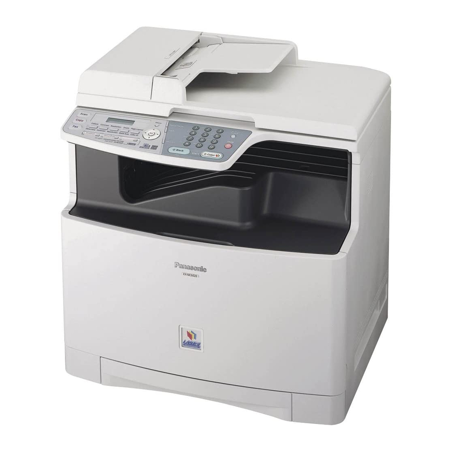
- Page 1 ORDER NO. KMF0811207CE Colour Laser Multi-Function Printer KX-MC6020HX Model No. KX-FAP317E/X (Optional lower input tray) KX-FAB318E/X (Optional Automatic duplex unit) (for Eastern Europe) © Panasonic Communications Co., Ltd. 2008. Unau- thorized copying and distribution is a violation of law.
-
Page 2: Table Of Contents
KX-MC6020HX TABLE OF CONTENTS PAGE PAGE 1 Safety Precautions -----------------------------------------------3 11.2. User Mode (The list below is an example of 1.1. For Service Technicians ---------------------------------3 the SYSTEM SETUP LIST the unit prints out.) - 163 1.2. AC Caution---------------------------------------------------3 11.3. Service Mode Settings (Example of a printed 1.3. -
Page 3: Safety Precautions
KX-MC6020HX 1 Safety Precautions 1. Before servicing, unplug the AC power cord to prevent an electric shock. 2. When replacing parts, use only the manufacturer's recommended components. 3. Check the condition of the power cord. Replace if wear or damage is evident. 4. -
Page 4: Personal Safety Precautions
KX-MC6020HX 1.3. Personal Safety Precautions 1.3.1. Moving Sections of The Unit Be careful not to let your hair, clothes, fingers, accessories, etc., become caught in any moving sections of the unit. The moving sections of the unit are the rollers and a gear. There is a separation roller and a document feed roller which are rotated by the document feed motor. -
Page 5: Service Precautions
KX-MC6020HX 1.4. Service Precautions 1.4.1. Precautions to Prevent Damage From Static Electricity Electrical charges accumulate on a person. For instance, clothes rubbing together can damage electric elements or change their electrical characteristics. In order to prevent static electricity, touch a metallic part that is grounded to release the static electricity. Never touch the electrical sections such as the power supply unit, etc. -
Page 6: Discarding Of P. C. Board
KX-MC6020HX 2.2. Discarding of P. C. Board When discarding P. C. Board, delete all personal information such as telephone directory and caller list or scrap P. C. Board. 2.3. Insulation Resistance Test 1. Unplug the power cord and short the two prongs of the plug with a jumper wire. 2. -
Page 7: Laser Beam And Fuser Unit Section
KX-MC6020HX 2.5. Laser Beam and Fuser Unit Section • The printer of this unit utilizes a laser. Use of controls or adjustments or performance of procedures other than those specified herein may result in hazardous radiation exposure. • The fuser unit is inside of the unit and gets hot. Do not touch it when removing the jammed paper. -
Page 8: Specifications
KX-MC6020HX 3 Specifications Applicable Lines: Public Switched Telephone Network Document Size: Max. 216 mm in width Max. 600 mm in length Effective Scanning Width: 208 mm Effective Printing Width: A4: 202 mm Letter/ Legal: 208 mm Transmission Time*: Approx. 4 s/page (ECM-MMR Memory transmission)** Scanning Density: Scanning resolution: Up to 600 ×... -
Page 9: General/Introduction
KX-MC6020HX 4 General/Introduction 4.1. Optional Accessories Replacement toner cartridge* Replacement toner cartridge (high capacity)* Color Model No. Color Model No. Cyan KX-FATC501E/KX-FATC501X Cyan KX-FATC506E/KX-FATC506X Magenta KX-FATM502E/KX-FATM502X Magenta KX-FATM507E/KX-FATM507X Yellow KX-FATY503E/KX-FATY503X Yellow KX-FATY508E/KX-FATY508X Black KX-FATK504E/KX-FATK504X Black KX-FATK509E/KX-FATK509X Prints about 2,000 sheets of A4-size pages with a 5 % coverage using KX-FATC501E / KX-FATC501X / KX-FATM502E / KX- FATM502X / KX-FATY503E / KX-FATY503X and about 2,500 sheets using KX-FATK504E / KX-FATK504X. - Page 10 KX-MC6020HX 4.2.2. Error Message (Report) 4.2.2.1. CZECH 4.2.2.2. SLOVAK 4.2.2.3. HUNGARIAN...
- Page 11 KX-MC6020HX 4.2.3. Error Message (Display) 4.2.3.1. CZECH...
- Page 12 KX-MC6020HX...
- Page 13 KX-MC6020HX 4.2.3.2. SLOVAK...
- Page 14 KX-MC6020HX...
- Page 15 KX-MC6020HX 4.2.3.3. HUNGARIAN...
- Page 16 KX-MC6020HX...
-
Page 17: Precautions For Shipping
KX-MC6020HX 4.3. Precautions for Shipping KX-MC6000 series have structural possibility that the waste toner may leak due to the vibration or the condition of the shipping. Therefore, appropriate preventive measures for toner leaking should be taken for each service type. Precautions for each service type are mentioned below. - Page 18 KX-MC6020HX Case 1) Exchange Service This service sends the replacement unit to customers first. Then the broken unit is sent to the service center. 1. Install dummy cartridges, which are used for toner leak prevention, before shipping the replacement units. •...
- Page 19 KX-MC6020HX Case 2) Regular Service 1. Request customers that send the broken unit with consumable supplies. 2. Response of service center after completing repairs • Remove all toners and drums and repack the repaired PNZE1MC6020M). (Refer to FIXTURES AND TOOLS unit to ship.
- Page 20 KX-MC6020HX 4.3.2. Repack Procedure Open the front cover (1) by holding the center part. Unlock the drum cartridge cover by pushing the tabs (2) in the direction of the arrows. Lift up the levers (3) and open the drum cartridge cover (4).
- Page 21 KX-MC6020HX Remove each toner cartridge (5) from the main unit. From left to right, yellow, magenta, cyan, black. • Do not touch the toner cartridge shutter at the bottom of the toner cartridge. The toner may spill out of the toner cartridge. Put each toner cartridge (6) into protective tray (7).
- Page 22 KX-MC6020HX Firmly grip the monochrome drum cartridge (13) and insert the protec- tive tray (14) by sliding it toward you. • Do not touch or scratch the green drum surface (15) at the bottom of the drum cartridge. Put the protective cover (16). Apply shipping tapes (17) to the monochrome drum cartridge (18).
- Page 23 KX-MC6020HX Firmly grip the color drum cartridge (23) and insert protective tray (24) by sliding it toward you. • Do not touch or scratch the green drum surface (25) at the bottom of the drum cartridge. Put the protective cover (26). Apply shipping tapes (27) to color drum cartridge (28).
- Page 24 KX-MC6020HX Caution; Put the orange protector (30) to the main unit.
- Page 25 KX-MC6020HX Installing Orange protector...
- Page 26 KX-MC6020HX Lift the drum cartridge cover (31) and push down on the levers (32) to close. • Push the levers down until you hear a click to ensure that the cover is locked. Close the front cover. Apply shipping tapes (33) to the main unit.
- Page 27 KX-MC6020HX Put the packing sheet (34) on the lower packing case (35). Then put the main unit (36) on them. Wrap the main unit (37) by the packing sheet (38).
- Page 28 KX-MC6020HX Put the protection cover (39), (40) and (41). Pack the color drum cartridge (42), the monochrome drum cartridge (43) and 4 toner cartridges (44) into the upper protection cover (45).
- Page 29 KX-MC6020HX Pack the pad (46) and the accessory box (47) into the upper protection cover (48). Then put the upper packing cover (49). Put 4 joints (50) into the packing case (51).
-
Page 30: Features
KX-MC6020HX 5 Features 5.1. General Features General • Help function SUPER FINE: For very small-sized characters. Display: PHOTO: For photographs, shaded drawings, etc. 1. FEATURE LIST Broadcast 2. DIRECTORY • 250-sheet paper capacity (75 g/m 3. FAX RECEIVING Distinctive ring detection. 4. -
Page 31: Technical Descriptions
KX-MC6020HX 6 Technical Descriptions Note: LOW VOLTAGE POWER SUPPLY BOARD = PSU HIGH VOLTAGE POWER SUPPLY BOARD = HVU 6.1. Connection Diagram Co lo r Drum Unit Fuse resistance Mono Dru m U nit CHARGER Fuser SUP PLY Roller re sistance Ro lle r Ro ller POWER... -
Page 32: General Block Diagram
KX-MC6020HX 6.2. General Block Diagram Main Board SOC (IC300) This custom IC is used for general MFP operations. ARM11 operating at 400MHz. DDR-SDRAM Controller Controls DDR (Double Data Rate) SDRAM Memory. USB Controller with PHY Apply to USB 2.0 HS Scanner I/F Controls the CIS and AFE, and process the scan images. - Page 33 KX-MC6020HX FAN MOTOR This model has 2 FAN motors. One cools PSU and inside temprature. The other cools the fuser and others. SOLENOID and CLUTCH This model has 4 solenoids and 1 clutch. Forms the images on the OPC DRUM of the each CYMK by rotating polygon motor and reflecting 4 laser beam against polygon. SENSORS Composed of 3 switches and 11 sensors of transmission type and 7 sensors of reflection type and 2 sensors of fuse resistance.
- Page 34 KX-MC6020HX (256/512Mbit) IC401 DDR-SDRAM (256/512Mbit) IC400 DDR-SDRAM (+24V) (+7V)
-
Page 35: Main Board Section
KX-MC6020HX 6.3. Main Board Section 6.3.1. Data Flow Data Flow [FAX Tx] 1. An analog image data is output from CIS unit to IC500. IC500 decode the analog data to digital data, and output to IC300. Scanner I/F in IC300 process image data and store it in IC400 and IC401 through DDR-SDRAM I/F. - Page 36 KX-MC6020HX Data Flow [PC Scan] 1. An analog image data is output from CIS unit to IC500. IC500 decode the analog data to digital data, and output to IC300. Scanner I/F in IC300 process image data and store it in IC400 and IC401 through DDR-SDRAM I/F.
- Page 37 KX-MC6020HX Data Flow [Monochrome copy] 1. An analog image data is output from CIS unit to IC500. IC500 decode the analog data to digital data, and output to IC300. Scanner I/F in IC300 process image data and store it in IC400 and IC401through DDR-SDRAM I/F.
- Page 38 KX-MC6020HX Description of Pin Distribution (IC300) PIN NO. PinName POWER SUPPLY VOLTAGE EXPLANATION vss_70 DOTCLKOUT 1.2V Video clock (Unused) PCIAD2 3.3V PCI Bus Address and Data [2] PCIAD5 3.3V PCI Bus Address and Data [5] PCIAD9 3.3V PCI Bus Address and Data [9] PCIAD13 3.3V PCI Bus Address and Data [13]...
- Page 39 KX-MC6020HX PIN NO. PinName POWER SUPPLY VOLTAGE EXPLANATION AE02 vss_11 AE03 BZRST25 2.5V BZ Control AE04 TXD1 2.5V Ethernet Transmit Data 1 AE31 EXMDMCS 3.3V Extended Modem CS (Unused) AE32 3.3V General port 2 (Used for Poligon clock) AE33 3.3V General port 3 (Used for Polygon Motor Control) AE34 3.3V...
- Page 40 KX-MC6020HX PIN NO. PinName POWER SUPPLY VOLTAGE EXPLANATION AL19 USBDVSSA12P PLL GND for USB controller AL20 vss_65 AL21 NCCDON 3.3V CCD Power Control AL22 vddio33pcix_11 - 3.3V POWER SUPPLY AL23 IO38 3.3V General port 38/UARTTXD3 (Transfer data for UART) AL24 vdd9 1.2V POWER SUPPLY...
- Page 41 KX-MC6020HX PIN NO. PinName POWER SUPPLY VOLTAGE EXPLANATION AN14 USBOVDDA12_ 1.2V Squeich POWER for USB controller AN15 USBCXIN 3.3V OSC for USB controller (25MHz) AN16 USBDVSSA33_ Bias for USB controller BIAS AN17 USBDDM 3.3V USB Device Signal AN18 USBDVDDA12_ 1.2V Squeich POWER for USB controller AN19 AFESIFDOUT...
- Page 42 KX-MC6020HX PIN NO. PinName POWER SUPPLY VOLTAGE EXPLANATION PCIAD11 3.3V PCI Bus Address and Data [11] PCIAD15 3.3V PCI Bus Address and Data [15] PCIAD18 3.3V PCI Bus Address and Data [18] PCIAD22 3.3V PCI Bus Address and Data [22] PCIAD25 3.3V PCI Bus Address and Data [25]...
- Page 43 KX-MC6020HX PIN NO. PinName POWER SUPPLY VOLTAGE EXPLANATION PCIAD4 3.3V PCI Bus Address and Data [4] vddio33pcix_3 3.3V POWER SUPPLY PCIAD8 3.3V PCI Bus Address and Data [8] vss_49 PCIAD16 3.3V PCI Bus Address and Data [16] vdd1 1.2V POWER SUPPLY PCIAD23 3.3V PCI Bus Address and Data [23]...
- Page 44 KX-MC6020HX PIN NO. PinName POWER SUPPLY VOLTAGE EXPLANATION vddio25_6 2.5V POWER SUPPLY SDCLK2 2.5V DDR-SDRAM Clock 2 NSDRAS 2.5V DDR-SDRAM Row Address Strobe vss_46 vss_47 SCIO20 3.3V General port 20 with schmitt. (Used for detecting CIS home position ) SCIO10 3.3V General port 10 with schmitt.
- Page 45 KX-MC6020HX PIN NO. PinName POWER SUPPLY VOLTAGE EXPLANATION vss_45 IO24 3.3V General port 24 (Used for poligon motor lock detecting ) 3.3V General port 1 (Used for External Tel Relay control) LSI_PROCMON O 3.3V LSI Test (Unused) SDMD16 2.5V DDR-SDRAM Data [16] SDMD17 2.5V DDR-SDRAM Data [17]...
- Page 46 KX-MC6020HX PIN NO. PinName POWER SUPPLY VOLTAGE EXPLANATION vss_15 vss_16 vss_17 vss_18 vss_19 vss_20 IO19 3.3V General port 19 (Unused) IO20 3.3V General port 20 (Used for power management) IO23 3.3V Genaral port 23/DMA INT (Used for INT control) Description of Pin Distribution (IC600) PIN NO.
- Page 47 KX-MC6020HX PIN NO. PinName Power SUPPLY VOLTAGE EXPLANATION NPCIPERR +3.3V PCI Bus Parity Error NPCISERR +3.3V PCI Bus System Error NDDRCS +2.5V DDR-SDRAM Chip Select DDRCLK +2.5V DDR-SDRAM Clock NDDRCLK +2.5V DDR-SDRAM Clock DDRCKE +2.5V DDR-SDRAM Clock Enable DDRBA0 +2.5V DDR-SDRAM Bank Address0 DDRBA1 +2.5V...
- Page 48 KX-MC6020HX PIN NO. PinName Power SUPPLY VOLTAGE EXPLANATION FRMA2 +3.3V Flash/Mask ROM Address [2] FRMA1 +3.3V Flash/Mask ROM Address [1] FRMA0 +3.3V Flash/Mask ROM Address [0] FRMD7 +3.3V Flash/Mask ROM Data [7] FRMD6 +3.3V Flash/Mask ROM Data [6] FRMD5 +3.3V Flash/Mask ROM Data [5] FRMD4 +3.3V...
- Page 49 KX-MC6020HX PIN NO. PinName Power SUPPLY VOLTAGE EXPLANATION EMPLEDM +3.3V LED Control of Toner Sensor for Magenta EMPLEDC +3.3V LED Control of Toner Sensor for Cyan EMPK +3.3V Toner Detection Terminal for Black EMPY +3.3V Toner Detection Terminal for Yellow EMPM +3.3V Toner Detection Terminal for Magenta...
- Page 50 KX-MC6020HX PIN NO. PinName Power SUPPLY VOLTAGE EXPLANATION DVDD4 +1.5V Power Supply for DLL VDD15_1 +1.5V Power SUPPLY VDD15_2 +1.5V Power SUPPLY VDD15_3 +1.5V Power SUPPLY VDD15_4 +1.5V Power SUPPLY VDD15_5 +1.5V Power SUPPLY VDD15_6 +1.5V Power SUPPLY VDD15_7 +1.5V Power SUPPLY VDD15_8 +1.5V...
- Page 51 KX-MC6020HX PIN NO. PinName Power SUPPLY VOLTAGE EXPLANATION GND_37 GND_38 GND_39 GND_40 6.3.2. RTC Backup Circuit 1. Function This unit has a lithium battery (B300) which works for the Real Time Clock IC (RTC: inside IC300). The RTC continues to work, backed up by a lithium battery even when the power switch is OFF. 2.
-
Page 52: Block Diagram
KX-MC6020HX 6.3.4. TEL Line Section Composed of ITS circuit and NCU circuit. 6.3.4.1. Description of Block Diagram in Analog Section Function The analog section works as an interface between the telephone line. DAA control ITS circuit and NCU circuit. DAA control signals are output from Soc IC300. Circuit Operation [NCU]: Network Control Unit the NCU is comprised of the following;... -
Page 53: Ncu Section
KX-MC6020HX 6.4. NCU Section 6.4.1. General This section is the interface between the telephone line and external telephone. It is composed of an EXT. TEL line relay (RLY100), bell detection circuit, TAM interface circuit and line amplifier. 6.4.2. EXT. TEL. Line Relay (RY100) 1. -
Page 54: Its (Integrated Telephone System) And Monitor Section
KX-MC6020HX 6.5. ITS (Integrated Telephone System) and Monitor Section 6.5.1. General The general ITS operation is performed by IC200 which has a handset circuit. The alarm tone, the key tone, and the beep are output from Soc IC300. 6.5.1.1. Telephone Monitor 1. -
Page 55: Cis Control Section
KX-MC6020HX 6.6. CIS Control Section The scanning block of this device consists of a control circuit and a CIS (contact image sensor), and AFE (Analog Front End) includ- ing A/D Converter. When an original document is inserted and the start button is pressed, pin A3 of IC300 goes to a low level and the transistor Q503 is turned on. -
Page 56: Motor Drive Section
KX-MC6020HX 6.7. Motor Drive Section 6.7.1. Engine Motor Control Circuit 6.7.1.1. BK Motor Control Circuit 1. Functions This circuit is used for driving the BK motor which supplies the rotation to the monochrome drum cartridge, black toner car- tridges, accumulator unit, paper feed unit ,and fuser unit. The BK motor control signals are explained as follows. 2. - Page 57 KX-MC6020HX 3. Sequence Control 6.7.1.2. Color Motor Control Circuit 1. Functions This circuit is used for driving the color motor which supplies the rotation to the color drum cartridge and color toner cartridges. The color motor control signals are explained as follows : 2.
- Page 58 KX-MC6020HX 3. Sequence Control...
- Page 59 KX-MC6020HX 6.7.2. Scanner Motor Drive Circuit General Scanner motor drive circuit consists of motor current control circuit ,FB (Flat Bed) motor drive and ADF (Auto Document Feeder: equipped model only) motor drive. 6.7.2.1. Motor Current Control Circuit 1. Circuit explanation According to the scan speed, each motor current is controlled for appropriate value.
- Page 60 KX-MC6020HX 6.7.2.2. FB (FLATBED) Motor Drive Circuit 1. Functions This motor functions for main operations includes FAX transmission, FB copy and PC scan. This motor feeds CIS unit with synchronizing for reading. 2. Motor operation During motor driving, pin AL33 of IC 300 become low level, then motor drive IC401 is activated. Stepping pulses are output from IC300 pins AN34, AM33, AM34, AM31, AP32 and AN32 causing drive IC401 pin 3, 7, 9 and 13 to drive the motor coil.
- Page 61 KX-MC6020HX 6.7.3. ADU (Automatic Duplex Unit (Option)) Motor Drive Circuit General ADU (Automatic Duplex Unit (Option)) motor drive circuit consists of motor current control circuit as well as Scanner motor. 6.7.3.1. Motor Current Control Circuit 1. Circuit explanation According to the print speed, each motor current is controlled for appropriate value. When print speed is low, motor current is decreased to prevent the vibration during motor rotation.
- Page 62 KX-MC6020HX 6.7.3.2. ADU (Automatic Duplex Unit (Option)) Motor Drive Circuit 1. Function The duplex printing is possible by the installation of Optional Automatic Duplex Unit (See Optional Accessories (P.9)). The motor in ADU feeds paper switched back to the registration roller at the duplex printing mode. 2.
- Page 63 KX-MC6020HX 6.7.4. Optional Lower Input Tray Motor (OPF Motor) Drive Circuit General Optional Lower Input Tray (Option) motor drive circuit consists of motor current control circuit as well as Scanner motor. 6.7.4.1. Motor Current Control Circuit 1. Circuit explanation According to the print speed, each motor current is controlled for appropriate value. When print speed is low, motor current is decreased to prevent the vibration during motor rotation.
- Page 64 KX-MC6020HX 6.7.4.2. Optional Lower Input Tray Motor (OPF Motor) Drive Circuit 1. Functions This MFP can add Optional Lower Input Tray for improv- ing the performance. (See Optional Accessories (P.9)) OPF motor feeds the paper in this tray to the registration roller. 2.
-
Page 65: Timing Chart And Waveform Of Scanner Motors
KX-MC6020HX 6.8. Timing Chart and Waveform of Scanner Motors Control sequence and waveform of both FB and ADF motor are almost same. 6.8.1. Normal 1-2 Phase Excitation (Half Step) 1. Timing chart 2. Wave form... - Page 66 KX-MC6020HX 6.8.2. Flat Torque 1-2 Phase Excitation (Half Step) 1. Timing chart 2. Wave form...
- Page 67 KX-MC6020HX 6.8.3. W 1-2 Phase Excitation (Quarter Step) 1. Timing chart 2. Wave form...
- Page 68 KX-MC6020HX 6.8.4. Drive Mode of FB and ADF Motor Correspondent table of operation...
-
Page 69: Timing Chart And Waveform Of Optional Unit Motors
KX-MC6020HX 6.9. Timing Chart and Waveform of Optional Unit Motors 6.9.1. Normal 1-2 Phase Excitation (Half Step) Control sequence and waveform of both Optional ADU (Automatic Duplex Unit) and Optional Lower Input Tray motor are almost same. 1. Timing chart 2. -
Page 70: Fan Section
KX-MC6020HX 6.10. Fan Section 6.10.1. Fuser Fan This FAN is designed to cool the fuser. The FAN starts to rotate when AD34 or AC31 of IC300 turns to High level. Depending on the operation mode, FAN speed is controlled to high, low, or stop. The FAN speed is determined by the logic of AD34 and AC31 of IC300. - Page 71 KX-MC6020HX 6.10.2. PSU Fan This FAN is designed to cool the PSU and inside temperature. The FAN starts to rotate when AC32 or AC33 of IC300 turns to High level. Depending on the operation mode, FAN speed is controlled to high, low, or stop. The FAN speed is determined by the logic of AC32 and AC33 of IC300.
-
Page 72: Solenoid Driver Section
KX-MC6020HX 6.11. Solenoid Driver Section The solenoid drive circuit controls Regist Clutch ,Pickup Solenoid, FTR Solenoid, ADU Solenoid, and PCK Solenoid. These solenoid and clutch are designed to be driven 24V. 24V power supply (SOLPWR_F) for solenoid driving is controlled by IC600, and power is supplied when D11 (PB0_SOLPWR) is in High Level. -
Page 73: Lsu (Laser Scanning Unit) Section
KX-MC6020HX 6.12. LSU (Laser Scanning Unit) Section 6.12.1. LSU (Laser Scanning Unit) Layout A laser diode generates the laser beam, and lenses and mirror in the laser scanner direct the beam to the OPC drum. The beam is made parallel by the collimator lens and is directed at the rotating polygon mirror, attached with the polygon motor. The beam is made parallel by the collimator lens and is directed at the rotating polygon mirror. -
Page 74: Circuit Diagram
KX-MC6020HX 6.12.2. Circuit Diagram 6.12.2.1. Block Diagram NVOUTK,NVOUTC,NVOUTM,NVOUTY There signals are the actual raster image data being printed for each color (NVOUTK: Black, NVOUTC: Cyan, NVOUTM: Magenta, NVOUTY: Yellow). When the signal NVOUTK (Pin11 of IC700) is low, the laser for Black color is turned on. When the signal NVOUTC (Pin8 of IC700) is low, the laser for Cyan color is turned on. - Page 75 KX-MC6020HX 6.12.2.2. Circuit Diagram...
-
Page 76: Timing Diagram
KX-MC6020HX 6.12.3. Timing Diagram Figure1. LD Drive Circuit Timing Diagram... - Page 77 KX-MC6020HX Figure2. APC Detail Timing Diagram during 1-scan...
-
Page 78: Sensors And Switches Section
KX-MC6020HX Figure3. Scanning Motor Operation Timing 6.13. Sensors and Switches Section All of the sensors and switches are shown below. Sensor Name Sensor Location Reference number Message Error OPC home sensor Sensor Board PS301,PS302 [CALL SERVICE 19] FTR home sensor Sensor Board PS303 [CALL SERVICE 13]... - Page 79 KX-MC6020HX Sensor Name Sensor Location Reference number Message Error 23 Option OPF cassette sensor Op OPF Sensor Board PC651 [CHECK INSTALL INPUT TRAY #2] 24 Option OPF cover switch Op OPF (Push SW) [TRAY #2 LEFT COVER OPEN] 25 Option ADU jam sensor Op ADU Board PC501 [PAPER JAMMED]...
- Page 80 KX-MC6020HX 6.13.2. FTR Home Sensor This sensor detects whether the FTR is at its home position or not. When the FTR is not at its home position, a shelter plate closes the sensor light . So the photo-transistor turns off and the input signal of IC300-L34pin becomes high level. When the FTR is not at its home position, a shelter plate lets the sensor light pass.
- Page 81 KX-MC6020HX 6.13.4. Registration and Paper (Paper Sensor) This sensor detects whether there are recording papers in the paper tray #1 or not. When there are recording papers in the tray, a shelter plate closes the sensor light. So the photo-transistor turns off and the input signal of IC300-M31pin becomes high level. When there no recording papers in the tray, a shelter plate lets the sensor light pass.
- Page 82 KX-MC6020HX 6.13.6. Registration and Paper Cassette Sensor This sensor detects whether the paper tray #1 is set or not. When there is the paper tray, a shelter plate closes the sensor light. So the photo-transistor turns off and the input signal of IC300-M32pin becomes high level. When there is not the paper tray, a shelter plate lets the sensor light pass.
- Page 83 KX-MC6020HX 6.13.8. CIS Home Sensor This sensor detects whether the carriage of CIS is at its home position or not. When the carriage is at its home position, a shelter plate closes the sensor light. So the photo-transistor turns off and the input signal of IC300-J32pin becomes high level. When the carriage is not at its home position, a shelter plate lets the sensor light pass.
- Page 84 KX-MC6020HX 6.13.10. ADF Read Position Sensor This sensor detects the front edge of the document. When the front edge of the document is detected, the shelter plate closes the sensor light. So the photo-transistor turns off and input signal of IC300-G34pin becomes high level. When the front edge of the document is not detected, the shelter plate lets the sensor light pass.
- Page 85 KX-MC6020HX 1. Waste Toner Empty 2. Waste Toner Full (detection by hard) State Display Near Waste Toner Full WASTE TONER FULL Waste Toner Full WASTE TONER REPLACE...
-
Page 86: Toner Sensor
KX-MC6020HX 6.13.12. Toner Sensor This sensor detects the toner cartridge and the toner level. The toner cartridge is detected just after the power is turned ON or the covers are closed. (The same with each color) The toner level is detected by LED light through the cartridge when the toner is decreased to a certain level. The phototransistor detects the light, causing the input levels of IC702 (Yellow, Magenta) and IC703 (Cyan, Black) to start dropping. - Page 87 KX-MC6020HX 1. Toner Full (Toner Cartridge Set)
- Page 88 KX-MC6020HX 2. Toner Empty (detection by hardware) 3. No Toner Cartridge State Display No Toner Cartridge TONER CARTRIDGE NOT INSTALLED Near Black Toner End BLACK TONER LOW Near Cyan Toner End CYAN TONER LOW Near Magenta Toner End MAGENTA TONER LOW Near Yellow Toner End YELLOW TONER LOW Black Toner End...
- Page 89 KX-MC6020HX 6.13.13. Drum Cartridge Virgin Sensor This sensor detects the drum cartridge and lifetime. The drum cartridge is detected by measuring the resistance inside the cartridge just after the power is turned on or the covers are closed. (The same with each color) As for the lifetime detection of the drum cartridge, counting the OPC rotation is to be started when the drum cartridge is judged as new by measuring the resistance in the drum cartridge.
- Page 90 KX-MC6020HX 6.13.14. Waste Toner Bottle Switch This switch detects whether the waste toner bottle is set or not. When there is the waste toner bottle, the input signal of IC600-B3pin becomes low level. When there is not the waste toner bottle, the input signal of IC600-B3pin becomes high level. Signal (IC600-B3pin) Toner is set Low level...
- Page 91 KX-MC6020HX 6.13.17. 5V Interlock Switch This switch is designed for safety. Opening and closing the front/left cover switches ON/OFF 5V supply to LSU laser power supply. 6.13.18. Handset Hook Switch When the handset is raised, the switch is turned off, and the signal of IC300-P34pin becomes low level. When the handset is settled, the switch is turned on, and the signal of IC300-P34pin becomes high level.
- Page 92 KX-MC6020HX 6.13.19. Color Registration Detection Circuit 1. Summary This circuit is designed to calculate the horizontal and vertical drift, skewness, etc. between each color by measuring end-to- end dimension of each color pattern printed on the accumulator belt. 2. Calibration Before the pattern detection, the amount of light emitting from the sensor should be adjusted so that the sensor output voltage of the accumulator belt stay within 2.75V~3.1V.
- Page 93 KX-MC6020HX...
- Page 94 KX-MC6020HX 4. Color registration detection circuit and sensor circuit...
- Page 95 KX-MC6020HX 6.13.20. Humidity/Temperature Sensor Circuits The temperature/humidity sensor board has the temperature and humidity sensors. The TEMP is an analog signal, which informs the information concerning the printer environment temperature to IC300 (SOC). IC300 receives this analog signal, converts it to a digital signal internally and detects the printer environment temperature. The HUMI is an analog signal, which informs the information concerning the printer environment humidity.
- Page 96 KX-MC6020HX 6.13.20.1. Temperature Sensor (Characteristics of Temperature Detection Thermistor) Temperature Resistance VTH (V) ADCR Temperature Resistance VTH (V) ADCR °C) °C) Value (kΩ) (TYP) (Standard) (Standard) Value (kΩ) (TYP) (Standard) (Standard) (TYP) (TYP) 34.06 2.551 0xC6 32.31 2.520 0xC3 7.653 1.431 0x6F 30.66...
- Page 97 KX-MC6020HX 6.13.20.2. Humidity Sensor (Characteristics of Humidity Detection Thermistor)
- Page 98 KX-MC6020HX 6.13.21. Optional OPF Paper Sensor This sensor detects whether there are recording papers in the Optional paper tray or not. When there are recording papers in the tray, a shelter plate closes the sensor light. So the photo-transistor turns off and the input signal of IC300-J33pin becomes high level. When there no recording papers in the tray, a shelter plate lets the sensor light pass.
- Page 99 KX-MC6020HX 6.13.23. Optional OPF Cassette Sensor This sensor detects whether the Optional paper tray is set or not. When there is the Optional paper tray, a shelter plate closes the sensor light. So the photo-transistor turns off and the input signal of IC300-F34pin becomes high level. When there is not the Optional paper tray, a shelter plate lets the sensor light pass.
- Page 100 KX-MC6020HX 6.13.24. Optional OPF Cover Switch This switch detects whether the OPF cover is open or closed. When the cover is closed, the input signal of IC300-H34pin becomes low level. When the cover is open, the input signal of IC300-H34pin becomes high level. Signal (IC300-H34Pin) Cover Close Low Level...
-
Page 101: Operation Board Section
KX-MC6020HX 6.14. Operation Board Section The unit consists of a LCD (Liquid crystal display), KEYs, and LEDs (light-emitting diodes). They are controlled by the Gate Array (IC201) and SOC (IC300 on Main board). The key matrix table is shown below. 1. -
Page 102: Lcd Section
KX-MC6020HX 6.15. LCD Section The Gate Array (IC201) works only for writing the ASCII code from the data bus (D4~D7). V0 is supplied for the LCD drive. R118 and R117 are density control resistors. Consequently, in this unit, the timing (positive clock) is generated by the LCD interface circuitry in the gate array (IC201). -
Page 103: Heat Lamp Control Circuit
KX-MC6020HX 6.16. Heat Lamp Control Circuit The temperature of the fixing part of the Fuser Unit is converted to a voltage by THERMISTOR and input to IC300-U34pin. The heat lamp is turned on/off by the HTRCTL signal (IC600-G17pin) through the photo triac (PC2) and the triac (CR001). And two thermostats are set on the AC line as the safety devices. - Page 104 KX-MC6020HX...
- Page 105 KX-MC6020HX 2. Safety Protection a. 2 thermostats are provided with the Fuser unit, and the heater circuit is shut down when their surface temperatures becomes over 180°C. b. When the temperature becomes over 205°C, The heater control circuit of IC300 has the built-in function that the software turns off the heater control automatically.
- Page 106 KX-MC6020HX Temperature AD Value (DEC) HEX reading Temperature AD Value (DEC) HEX reading Temperature AD Value (DEC) HEX reading °C °C °C Note: The value is displayed on LCD at Test Functions (P.154) [#815].
-
Page 107: Hvu (High Voltage Power Supply Board) Section
KX-MC6020HX 6.17. HVU (High Voltage Power Supply Board) Section 6.17.1. High Voltage Circuit This board outputs 12 high voltages used for electronic photographic process. The 12 voltages consists of 2 charge ( VCH/YMC, VCH/K : -1001V ~ -1405V ) for color (YMC) OPC and black OPC, 4 development bias ( VB/Y, VB/M, VB/C, VB/K : DC -100V ~ - 300V + AC400V ) for each color, 4 supply bias ( VSR/Y, VSR/M, VSR/C, VSR/K : -200V ~ -400V), FTR bias ( FTR : 0V ~ 1800V ), STR bias ( STR : 0 ~ 5000V ). - Page 108 KX-MC6020HX 6.17.3. Development Bias Control Circuit This circuits of a DC-DC converter and a DC-AC converter. The DC-DC converter boosts +24V to approximately -100 ~ -300V for the development bias. The DC-AC converter adds the rectangular AC voltage to development bias. AC frequency value is approximately 800/1000 Hz that is determined by the external clock signal SCLKHV from IC300 (ASIC) on the main board.
- Page 109 KX-MC6020HX 6.17.6. Second Transfer Control Circuit (STR) This circuit consists of a DC-DC converter, which boosts +24V to approximately 0 ~ 5000V for the second transfer bias (maxi- mum current rating 100µA). This voltage value is controlled by the D/A converter circuit on the high voltage board. 6.17.7.
- Page 110 KX-MC6020HX 6.17.9. D/A Convertor (8bit, 12ch) Interface Circuit This circuit is for generating the analog voltage signals that control the high voltages (charge bias, development bias, FTR bias, and STR bias). Signal Name Location Description SCLKHV Pin 8 of CN890 This is the shift clock signal (93.4kHz at data transferring).
- Page 111 KX-MC6020HX 6.17.10. Interface...
-
Page 112: Main Board Section
KX-MC6020HX 6.18. Main Board Section 6.18.1. Main Unit Power Supply Circuit Block Diagram DC-DC and regulator generate desired voltage from low voltage power supply of 7V. (Refer to the block diagram shown below.) 1. Power supply diagram 2. Power ON sequence Power ON/OFF sequence is controlled by the sequencer. - Page 113 KX-MC6020HX 6.18.2. DC-DC Power Supply Circuit (3.3V / 2.5V / 1.5V / 1.2V) IC1 and IC2 are 2ch-output PWM type DC-DC converter controllers, which make up step down type DC-DC converter circuit with Pch power MOSFET Q3, Q4, Q5, and Q6, coil of L1, L2, L3, and L4 and schottky diode of D1, D2, D3, and D4. The oscillation frequency in operation of this DC-DC converter is set to about 410kHz.
- Page 114 KX-MC6020HX 1. 3.3V/2.5V booting waveform example (self booting waveform without sequencer) 2. 1.2V/1.5V booting waveform example...
-
Page 115: Reset Circuit
KX-MC6020HX 6.18.3. Regulator Circuit (5V) IC4 and IC6 are turned ON when 3.3V power supply is booted, 5V is generated from 7V-input. 6.18.4. Regulator Circuit (1.25V) IC3 and IC7 generate termination voltage 1.25V for DDR_SDRAM (IC400, 401, 960). 6.18.5. Reset Circuit Reset IC (IC5) monitors 5VD2. -
Page 116: Psu (Low Voltage Power Supply Board) Section
KX-MC6020HX 6.19. PSU (Low Voltage Power Supply Board) Section The low voltage power supply board circuit generates +7V and +24Vdc. It also supplies AC voltage to the halogen heat lamp in the fuser unit. The low voltage power supply board uses the switching regulator method. [Input Circuit] The input current goes into the input rectifier circuit through the filter circuit. -
Page 117: Mechanical Operation
KX-MC6020HX 6.20. Mechanical Operation 6.20.1. Color Motor Rotation Travel The Color Motor (DC Motor) is for driving the 3 Color (Cyan, Magenta, Yellow) Drum Cartridges and 3 Color (Cyan, Magenta, Yel- low) Toner Cartridges. Number Block Name Description Refer to •... - Page 118 KX-MC6020HX 6.20.1.1. Color Motor Rotation Travel for Driving 3 Color (CMY) Drum Cartridges...
- Page 119 KX-MC6020HX 6.20.1.2. Color Motor Rotation Travel for Driving 3 Color (CMY) Toner Cartridges...
- Page 120 KX-MC6020HX 6.20.2. BK Motor Rotation Travel The BK Motor (DC Motor) is for driving the Black Drum Cartridge, Black Toner Cartridge, Fuser Unit, Optional Automatic Duplex Unit (ADU), Accumulator Unit and Waste Toner Cartridge. Number Block Name Description Refer to Black Drum Cartridge Joint (OPC) The Motor Rotation is transmitted to Refer to BK Motor Rotation Travel for Driving Black...
- Page 121 KX-MC6020HX 6.20.3. BK Motor Rotation Travel for Driving Black Drum Cartridge...
- Page 122 KX-MC6020HX 6.20.3.1. BK Motor Rotation Travel for Driving Accumulator Unit and Black Toner Cartridge...
- Page 123 KX-MC6020HX 6.20.3.2. BK Motor Rotation Travel for Driving Fuser Unit CROSS REFERENCE: BK Motor Rotation Travel for Driving Waste Toner Cartridge (P.124). BK Motor Rotation Travel for Driving Accumulator Unit (P.125).
- Page 124 KX-MC6020HX 6.20.3.3. BK Motor Rotation Travel for Driving Waste Toner Cartridge Cross Reference BK Motor Rotation Travel for Driving Fuser Unit (P.123).
- Page 125 KX-MC6020HX 6.20.3.4. BK Motor Rotation Travel for Driving Accumulator Unit Cross Reference BK Motor Rotation Travel for Driving Fuser Unit (P.123).
-
Page 126: Print Process
KX-MC6020HX 6.20.4. Print Process This Laser Printer creates an image on paper using a technique called laser electrophotography. The printer uses the electro- graphic process known as Discharged Area Development, or “write black”. In this process, a digitally modulated laser scans later- ally across a rotating OPC (Organic Photo Conductive) drum that has been negatively charged. -
Page 127: Laser Exposure
KX-MC6020HX Each block is explained in the following sections 1.Charging (See P.127) 5. Paper Pickup (See P.129) 2. Laser Exposure and Scanning (See P.127) 6. Toner Transfer to Paper (See P.130) 3. Developing (See P.128) 7. Fusing (See P.131) 4. Toner Transfer to the Accumulator Belt (See P.129) 8. Paper Exit and Paper Switchback (See P.132) 6.20.4.1. - Page 128 KX-MC6020HX 6.20.4.2.2. Laser Scanning A laser diode generates the laser beam, and lenses and mirror in the laser scanner direct the beam to the OPC drum. The beam is made parallel by the collimator lens and is directed at the rotating polygonal mirror, attached with the polygon motor. The polygon mirror rotates at a constant revolutions approximately 22,000 per minute.
-
Page 129: Paper Pickup
KX-MC6020HX 6.20.4.4. Toner Transfer to the Accumulator Belt As the OPC drum rotates, in contact with the accumulator belt, which is rotating at the same speed. Located under the accumulator belt at the contact point with the OPC drum, the first transfer roller carries a charge approximately +700 volts (FTR voltage). This strong potential attracts and holds the toner from the OPC drum to the accumulator belt. - Page 130 KX-MC6020HX printed on the paper. The registration sensor detects whether the sheet of paper arrived at the registration roller after being properly picked and traveling through the paper feed rollers in the optional lower Input tray. The paper feed unit has the standard paper cassette paper empty and registration sensors. The standard paper cassette has the MPT paper empty sensor for multi-purpose tray and the paper size detection levers.
- Page 131 KX-MC6020HX 6.20.4.7. Fusing After toner image has been applied to the paper, it passes through the fuser. When the BK motor starts to rotate, the Halogen Lamp is turned on, heating the heat roller. As a result, the fuser belt, contacted with the heat roller surface, is heated by the heat roller. A heated fuser belt melts the toner and pressure drives it into the paper.
- Page 132 KX-MC6020HX 6.20.4.8. Paper Exit and Paper Switchback 6.20.4.8.1. Normal Printing Mode (Not Duplex Printing Mode) After fusing, paper is fed to the output tray by the paper exit roller. Rotation from the BK motor is transmitted to the double teeth gear.
- Page 133 KX-MC6020HX 6.20.4.8.2. Duplex Printing Mode (Paper Switchback) The switchback solenoid is turned off by the time the top edge of paper passes by the paper jam sensor on the fuser unit. The switching lever engages with the switching gear-A, and the rotation of rotation switching gear-A is locked. As a result, the rotation from the BK motor is transmitted to the paper exit roller in order of numbers (1 - 7) through the double teeth gear.
-
Page 134: Location Of Controls And Components
KX-MC6020HX 7 Location of Controls and Components 7.1. Overview 7.1.1. Front view (1) ADF (Automatic Document Feeder) cover (2) Document guides (3) Document tray (4) Document tray extender (5) Document cover (6) Document exit (7) Document entrance (8) Power switch (9) Left cover (10) Handset (11) Left cover open lever... -
Page 135: Control Panel
KX-MC6020HX 7.2. Control Panel (1) Copy (2) Scan (3) Collate / Directory (4) Contrast (5) Resolution (6) Zoom / Quick Scan (7) Page Layout / Caller ID (8) Menu (9) Redial / Pause (10) Flash (11) Tone (12) Fax Auto Answer (13) Fax (14) Station keys (15) Broadcast... -
Page 136: Installation Instructions
• Do not leave the toner cartridge out of the protection bag for a long time. It will decrease the toner life. • We cannot be responsible for any damage to the unit or degradation of print quality which may occur from the use of a non-Panasonic toner cartridge and drum cartridge. • Do not add toner to the toner cartridge. - Page 137 KX-MC6020HX Lift up the levers (3) and open the drum cartridge cover (4). Remove the orange protector (5) by pulling it toward you, then pull it completely out from the unit.
- Page 138 KX-MC6020HX Remove the color drum cartridge from the protection bag. • Remove the shipping tape • Do not remove the monochrome drum cartridge from the protection bag before installing the color drum cartridge in step 8. • When holding the color drum cartridge, be sure to handle it over a table to prevent damage caused by dropping it from a high position.
- Page 139 KX-MC6020HX Remove the monochrome drum cartridge from the protection bag. • Remove the shipping tape. Detach the protective cap (15), then detach the upper seal cover by holding the tab (16). Firmly grip the monochrome drum cartridge (17) and remove the pro- tective tray (18) by sliding it toward you.
- Page 140 KX-MC6020HX Remove the 4 toner cartridges from the protection bags. • Remove the shipping tape. Remove each protective tray (23) by lifting up the toner cartridge (24). Insert each toner cartridge (25) in the appropriate color slot. From left to right, yellow, magenta, cyan, black. •...
- Page 141 • When replacing the color drum cartridge, hold the green lever using your left hand same as installing it. • To ensure that the unit operates properly, we recommend the use of Panasonic toner cartridge and drum cartridge (Refer to Specifications (P.8))
-
Page 142: Recording Paper
KX-MC6020HX 8.1.2. Recording Paper 8.1.2.1. Using the paper input tray The standard input tray unit can hold: — Up to 250 sheets of 75 g/m paper. — Up to 230 sheets of 80 g/m paper. — Up to 200 sheets of 90 g/m paper. - Page 143 KX-MC6020HX Pinch the right side of the recording paper guide (4), then slide it to match the paper size mark. Pinch the front and back recording paper guides (5) at the same time, then slide them together to match the paper size mark. •...
-
Page 144: Handset Unit
KX-MC6020HX Caution for the standard input tray • Do not drop the standard input tray. • Hold the standard input tray with both hands when removing or installing. The standard input tray weighs approximately 2.9 kg when the recording paper is fully installed. Do not touch the plate (1) on the left side of the standard input tray. - Page 145 KX-MC6020HX Lift the handset cradle in the direction of the arrow (4) to insert the tab (5), then insert the rib (6) by pushing the handset unit toward the unit. Pull out the handset cord holder (7) and pass the handset cord (8) through the handset cord holder.
- Page 146 KX-MC6020HX To remove the handset unit Disconnect the handset cord (1) from the handset, then remove the handset (2) from the handset cradle. Remove the handset cord from the handset cord holder (3), then close the handset cord holder. Pull the handset unit slightly forward (4), then lift it in the direction of the arrow (5) to remove the rib.
-
Page 147: Using The Scanner Glass
KX-MC6020HX 8.1.4. Documents The Unit Can Send 8.1.4.1. Using the Scanner Glass Note: • Confirm that there are no documents in the automatic document feeder. • Place the original onto the scanner glass gently. Do not press down too firmly to avoid malfunction. •... -
Page 148: Connecting To A Computer
8.1.5. Connecting to a computer Panasonic Multi-Function Station software enables the unit to carry out the following functions: - Printing on plain paper, thin and thick paper,transparencies, labels, envelopes and card stocks - Scanning documents and converting an image into text with Readiris OCR software ®... - Page 149 KX-MC6020HX 5 The [Connect Type] dialogue box appears. For USB connection 1. [Connect directly with a USB cable.] → [Next] • The [Connect Device] dialogue box will appear. 2. Connect the unit to a computer with the USB cable (1), then click [Next]. •...
-
Page 150: Connections
KX-MC6020HX 8.2. Connections Caution: • When you operate this product, the power outlet should be near the product and easily accessible. • Be sure to use the telephone line cord supplied with this unit. • Do not extend the telephone line cord. (1) Power cord •... - Page 151 KX-MC6020HX • A telephone handset cannot be connected directly to this unit. To talk to the other party, please connect an extension telephone. Using network router/network hub • We recommend using network routers/network hubs (6) under secure network environments. Consult your network administrator for firewall settings, etc.
-
Page 152: Operating Instructions
KX-MC6020HX 9 Operating Instructions 9.1. YOUR LOGO You can program your logo (name, company name, etc.) so that it appears on the top of each page sent. - Page 153 KX-MC6020HX 9.1.1. To Select Characters with The Dial Keypad The dial keypad is used to enter characters and numbers. 9.1.2. To Select Characters Using [ ] OR - Press [ ] or [ ] to move the cursor. - Press dial keys to enter characters and numbers. - Press [Stop] to erase the character or number highlighted by the cursor.
-
Page 154: Test Mode
KX-MC6020HX 10 Test Mode Note: LOW VOLTAGE POWER SUPPLY BOARD = PSU HIGH VOLTAGE POWER SUPPLY BOARD = HVU 10.1. Test Functions The codes listed below can be used to perform simple checks of some of the unit’s functions. When complaints are received from customers, they provide an effective tool for identifying the locations and causes of malfunctions. - Page 155 KX-MC6020HX Test Mode Type of Mode Code Function Operation after code input SENSOR CHECK Service Mode “8” “1” “5” First of all, press the copy button, and confirm the action of ON/OFF. For each sensor’s operation, refer to Sensors and Switches Section (P.78). LCD DISPLAY: 1: Standard cassette sensor 2: OPF cassette sensor...
- Page 156 KX-MC6020HX 10.1.1. DTMF Single Tone Transmit Selection Note: After performing this check, do not forget to turn the setting off. Otherwise, dialing in DTMF signal will not work. 10.1.2. Button Code Table...
-
Page 157: Service Mode
KX-MC6020HX 11 Service Mode The programming functions are used to program the various features and functions of the machine, and to test the machine. This facilitates communication between the user and the service man while programming the unit. Note: LOW VOLTAGE POWER SUPPLY BOARD = PSU HIGH VOLTAGE POWER SUPPLY BOARD = HVU 11.1. - Page 158 KX-MC6020HX 11.1.3. Specifications 11.1.3.1. Service Mode #884: History...
- Page 159 KX-MC6020HX 11.1.3.2. Service Mode #852: Color Printing Test 11.1.4. Service Function Table Code Function Set Value Effective Default Remarks Range Pause time set X 100 msec 001~600 ---------- Dial speed select 1:10 pps 1, 2 ---------- 2:20 pps V34 transmission start speed 0: Disable If the code 527 is set at 2, the code 507 and 508 1: 33.6...
- Page 160 KX-MC6020HX Code Function Set Value Effective Default Remarks Range Scanner test See (P.154). Motor test See (P.154). LED test See (P.154). LCD test See (P.154). KEY test See (P.154). T0 timer 001~255 001~255 Sets a higher value when the response from the other party needs more time during automatic FAX transmission.
- Page 161 KX-MC6020HX Code Function Set Value Effective Default Remarks Range HVU (Bais check) Test Pressing SET key starts STR Bias check test. Although "00" appears on the LCD, it isn't related to the test. Pressing STOP key finishes the test. Stop Drum Mode 1:Stop If the code 650 is set at 2,machine doesn't stop 2: Non stop...
- Page 162 KX-MC6020HX 11.1.5. Memory Clear Specification Execute Service Mode #550 when you want to reset the all setting data keeping the user information. Execute Service Mode #710 to clear the user information in case that Main Unit is recycled. Note: Please restart a power supply after clearing a memory.
-
Page 163: User Mode (The List Below Is An Example Of The System Setup List The Unit Prints Out.)
KX-MC6020HX 11.2. User Mode (The list below is an example of the SYSTEM SETUP LIST the unit prints out.) - Page 164 KX-MC6020HX Note: The above values are the default values.
-
Page 165: Service Mode Settings (Example Of A Printed Out List)
KX-MC6020HX 11.3. Service Mode Settings (Example of a printed out list) Note: The above values are the default values. -
Page 166: History
KX-MC6020HX 11.4. History Note: See the following descriptions of this report. Item No. (1) ~ (44) are corresponding to the listed items in Description of The His- tory Report(P.167). - Page 167 KX-MC6020HX 11.4.1. Description of The History Report (1) Usage Time of Recieve Mode (Tel Mode) (35) Accumulator Page Count (2) Usage Time of Recieve Mode (Fax Mode) (The number of rotation is converted. The standard paper (3) Usage Time of Recieve Mode (Tel/Fax Mode) size is A4 or Letter in accordance with the destination.) (4) Usage Time of Recieve Mode (Tad/Fax Mode) (36) Job Number of 1P/J (Page per Job)
-
Page 168: Troubleshooting Guide
KX-MC6020HX 12 Troubleshooting Guide Note: LOW VOLTAGE POWER SUPPLY BOARD = PSU HIGH VOLTAGE POWER SUPPLY BOARD = HVU 12.1. User Recoverable Errors If the unit detects a problem, one or more of the following messages will appear on the display. The explanations given in the [ ] are for servicemen only. - Page 169 KX-MC6020HX DISPLAY MESSAGE CAUSE AND REMEDY • The paper input tray is not installed correctly. Pull out the paper input tray and re-inset it. Note: • “#1”: Standard input tray • "#2": Optional input tray • "#1+#2": Standard input tray and optional input tray •...
- Page 170 KX-MC6020HX DISPLAY MESSAGE CAUSE AND REMEDY • Recording paper is not installed or the paper input tray has run out of paper. Install paper. • Recording paper is not fed into the unit properly. Reinstall paper. Note: • “#1”: Standard input tray •...
-
Page 171: User Recoverable Network Errors
KX-MC6020HX 12.2. User Recoverable Network Errors... - Page 172 KX-MC6020HX...
- Page 173 KX-MC6020HX...
-
Page 174: Remote Programming
KX-MC6020HX 12.3. Remote Programming If, after the call is connected, the customer describes the situation and it is determined that the problem can be corrected by making parameter changes, this function makes it possible to change parameters such as the user code and service code from another fax (using DTMF tones). - Page 175 KX-MC6020HX 12.3.1. Entering The Remote Programming Mode and Changing Service Codes CROSS REFERENCE: Program Mode Table (P.176)
- Page 176 KX-MC6020HX 12.3.2. Program Mode Table 12.3.2.1. User Function Basic features Code Function Set Value Default Remote Setting SET DATE & TIME mm/dd/yy hh:mm 01/01/08 YOUR LOGO --------- None YOUR FAX NUMBER --------- None LANGUAGE 1:ENGLISH / 2:CZECH / 3:SLOVAK / ENGLISH 4:HUNGARIAN LOCATION...
- Page 177 KX-MC6020HX Code Function Set Value Default Remote Setting SET FAX DEFAULT YES / NO Copy features Code Function Set Value Default Remote Setting COPY SETTING 1:#1 / 3:#2 / 4:#1+#2 COPY RESOLUTION 1:TEXT/PHOTO / 2:TEXT / 3:PHOTO TEXT/PHOTO PAGE LAYOUT HOLD 1:DISABLED / 2:ENABLED DISABLED ZOOM HOLD...
- Page 178 KX-MC6020HX 12.3.2.2. Service Function Code Function Set Value Default Remote Setting Pause time set 001~600 x 100msec Dial speed 1:10pps / 2:20 pps 10pps V34 transmission start speed (0:Disable/1:33.6/2:31.2/3:28.8/4:26.4/ 33600bps 5:24.0/6:21.6/7:19.2/8:16.8/) V34 reception start speed (0:Disable/1:33.6/2:31.2/3:28.8/4:26.4/ 33600bps 5:24.0/6:21.6/7:19.2/8:16.8/) Bell signal detect time 1~9 x 100msec CED frequency select 1:2100Hz / 2:1100Hz...
- Page 179 KX-MC6020HX Code Function Set Value Default Remote Setting DTMF ON time 060~200msec DTMF OFF time 060~200msec Skew Correction 1: Valid / 2: Invalid Valid Color Registration Detection Timing 0~65535 History list --------- --------- Journal 2 --------- --------- Journal 3 --------- --------- History ---------...
-
Page 180: Troubleshooting Details
KX-MC6020HX 12.4. Troubleshooting Details 12.4.1. Outline Troubleshooting is for recovering quality and reliability by determining the broken component and replacing, adjusting or cleaning it as required. First, determine the problem then decide the troubleshooting method. If you have difficulty finding the broken part, determine which board is broken. - Page 181 KX-MC6020HX 12.4.3. Initialization There are two types of initialization, one is the short initialization (about 3 seconds) and the other is the long initialization (about 10 seconds). The short initialization makes the unit enter the standby mode. The long initialization makes the unit enter the standby mode after cleaning or detecting the rest of toner.
- Page 182 KX-MC6020HX 12.4.4. Simple Check List Note: Check according to the service code referring to Test Functions (P.154)
- Page 183 KX-MC6020HX 12.4.5. Simplified Troubleshooting Guide 12.4.5.1. Printing Symptom Cause Countermeasure Blank Print (P.204) Failed drum cartridge Replace drum cartridge Failed accumulator unit Replace accumulator unit FTR position Error Refer to CALL SERVICE 13 (P.196) Something wrong with movement of FTR cam Replace FTR cam Something wrong with changer solenoid Replace changer solenoid Damaged gear...
- Page 184 KX-MC6020HX Symptom Cause Countermeasure 14 Image is Skewed on the Overcapacity of paper cassette tray Remain paper level appropriately Paper(P.216) Wrong adjustment of paper guide Adjust paper guide to proper size Failed paper feed unit Replace paper feed unit Something wrong with secondary transfer roller Check secondary transfer roller movement Failed main board...
- Page 185 KX-MC6020HX Symptom Cause Countermeasure Paper Jams at the Fuser Jammed paper remaining Remove jammed paper Unit (P.225) Dirt or distorted on fuser belt Clean belt or replace fuser unit Dirt on pressure roller Clean roller or replace fuser unit Dirt or distorted on separator or paper guide. Clean parts or replace fuser unit Unhooked spring Install spring properly...
- Page 186 KX-MC6020HX 12.4.6. Call Service Troubleshooting Guide Call Service related error is most frequent. Call Service 1 ----- Polygon doesn’t rotate..Refer to LSU (Laser Scanning Unit) Section (P.73). • First, listen to the sound. If rotation sound isn't heard, check 24V line, POLON signal and POLCLK signal. If even a little of sound is heard, check XREADY signal.
- Page 187 KX-MC6020HX Call service 13 ----- FTR (The First Transfer Roller) position error..Refer to FTR Home Sensor (P.80). • Call service 13 appears when FTR does not return to the Home position. • First, replace the AU, and check the operation. •...
-
Page 188: Call Service
KX-MC6020HX 12.4.6.1. CALL SERVICE 1 "CALL SERVICE 1" means that the polygon motor inside the LSU does not rotate. The rotation of the polygon motor is detected by IC300-F23pin (NREADY). - Page 189 KX-MC6020HX 12.4.6.2. CALL SERVICE 2 "CALL SERVICE 2" means that the synchronous signal out of the LSU cannot be detected. The synchronous signal out of the LSU is detected by IC 300-G23pin. (NHSYNC) Note: As for the "Pulse" waveform of the above flow chart, see the timing chart.
- Page 190 KX-MC6020HX 12.4.6.3. CALL SERVICE 3 Call SERVICE 3 appears when one of following phenomena occurs. • In case that the fuser temperature does not reach the specified temperature within the specified time when the fuser is turned on: • In case that the fuser temperature becomes over the specified temperature when the fuser is turned on: * When Call Service 3 is occurred, the cause can be distinguished by service mode 655.
- Page 191 KX-MC6020HX 12.4.6.4. CALL SERVICE 4 Call SERVICE 4 appears when the fuser fan does not rotate or the rotation can not be detected even though the fun is rotating. Fuser FAN rotation is detected by pin A12 of IC600. Rotation detection takes a sampling every 100ms. Call Service appears when an error is found 10 times in a row. Make a copy 3 times after repair.
- Page 192 KX-MC6020HX 12.4.6.5. CALL SERVICE 5 “CALL SERVICE 5” means that main motor’s rotation detection signal (LD) does not become Low.
- Page 193 KX-MC6020HX 12.4.6.6. CALL SERVICE 6 “CALL SERVICE 6” indicates that abnormal charge voltage is output from the high voltage unit.
- Page 194 KX-MC6020HX 12.4.6.7. CALL SERVICE 11 Call SERVICE 11 appears when the PSU FAN motor does not rotate or the rotation can not be detected even though the fun motor is rotating. PSU FAN rotation is detected by pin C11 of IC600. Make a copy 3 times after repair.
- Page 195 KX-MC6020HX 12.4.6.8. CALL SERVICE 12 “CALL SERVICE 12” means that color motor’s rotation detection signal (LD) does not become Low.
- Page 196 KX-MC6020HX 12.4.6.9. CALL SERVICE 13 Call SERVICE 13 appears when the accumulator unit (AU) did not return to the home position within a specified time. CROSS REFERENCE: Note for Assembling (P.347).
- Page 197 KX-MC6020HX 12.4.6.10. CALL SERVICE 14 Call SERVICE 14 appears when the coil of solenoid or the electromagnetic clutch gets layer short. Target solenoids are as follows: Registration and Paper pickup solenoid, regist clutch solenoid, path switching solenoid for ADU, Black Drum driving solenoid, and accumulator junction/disjunction cam solenoid.
- Page 198 KX-MC6020HX 12.4.6.11. CALL SERVICE 15 Call SERVICE 15 appears when the standard pickup roller does not return to the home position within a specified time.
- Page 199 KX-MC6020HX 12.4.6.12. CALL SERVICE 16 Call SERVICE 16 appears when something is wrong with the virgin sensor in the Color drum cartridge. Specifically Call SERVICE 16 appears when the resistance fuse, which is used as a virgin sensor, is not blown out within a specified time.
- Page 200 KX-MC6020HX 12.4.6.13. CALL SERVICE 17 Call SERVICE 17 appears when something is wrong with the virgin sensor in Monochrome drum cartridge. Specifically Call SERVICE 17 appears when the resistance fuse, which is used as a virgin sensor, is not blown out within a specified time.
- Page 201 KX-MC6020HX 12.4.6.14. CALL SERVICE 18 Call SERVICE 18 indicates the watch dog time out error of the DC motor. This call service appears when periodic resistance mon- itoring of the firmware for resistances on IC600 is not conducted during the main motor or color motor driving.
- Page 202 KX-MC6020HX 12.4.6.15. CALL SERVICE 19 Call service 19 appears when one of following phenomena occurs. • In case that the pulse is not input from the encoder for Monochrome drum rotation detector when controlling the rotation of the Monochrome drum. •...
- Page 203 KX-MC6020HX 12.4.6.16. CALL SERVICE 20 Call SERVICE 20 appears when the LED of toner detection sensor is not lighted. Each color (Y, M, C, and Bk) has its own LED. Call SERVICE 20 appears when one of them is not lighted.
-
Page 204: Print Quality
KX-MC6020HX Print Quality 12.4.7. 12.4.7.1. Blank Print CROSS REFERENCE: CALL SERVICE 13 (P.196) - Page 205 KX-MC6020HX 12.4.7.2. All-black Print...
- Page 206 KX-MC6020HX 12.4.7.3. Missing Primary Color...
-
Page 207: Light Print
KX-MC6020HX 12.4.7.4. Light Print CROSS REFERENCE: CALL SERVICE 13 (P.196) - Page 208 KX-MC6020HX 12.4.7.5. Repeated Spots or Lines on Print in-line with Each Other...
- Page 209 KX-MC6020HX 12.4.7.6. Dark Vertical Line in Print...
- Page 210 KX-MC6020HX 12.4.7.7. White Horizontal Line or Band in all the Color of a Print...
- Page 211 KX-MC6020HX 12.4.7.8. Mis-transfer, Missing Portions of Toner...
- Page 212 KX-MC6020HX 12.4.7.9. Dirty Background...
- Page 213 KX-MC6020HX 12.4.7.10. Partial Primary Color Dots 12.4.7.11. Dark Irregular Streaks in Print...
- Page 214 KX-MC6020HX 12.4.7.12. Primary Color Irregular Streaks 12.4.7.13. Ghosting...
- Page 215 KX-MC6020HX 12.4.7.14. Unfused or Partially Fused Printing...
- Page 216 KX-MC6020HX 12.4.7.15. Image is Skewed on the Paper...
- Page 217 KX-MC6020HX 12.4.7.16. Stains on Back of Print...
- Page 218 KX-MC6020HX 12.4.7.17. No Printing on Edge of Print...
- Page 219 KX-MC6020HX 12.4.7.18. Image is not Centered on the Print When it Should Be...
- Page 220 KX-MC6020HX 12.4.8. Jam 12.4.8.1. Print Media Problem...
- Page 221 KX-MC6020HX 12.4.8.2. Print Media Skew...
- Page 222 KX-MC6020HX 12.4.8.3. Paper Jam at the Input Tray...
- Page 223 KX-MC6020HX 12.4.8.4. Paper Jams at the Registration Roller...
- Page 224 KX-MC6020HX 12.4.8.5. Paper Jams at the 2nd Transfer Roller...
- Page 225 KX-MC6020HX 12.4.8.6. Paper Jams at the Fuser Unit...
- Page 226 KX-MC6020HX 12.4.8.7. Paper Jam at the Exit Roller...
- Page 227 KX-MC6020HX 12.4.8.8. Wrong Paper Length Jams...
- Page 228 KX-MC6020HX 12.4.8.9. Paper Jams at the Optional Input Tray...
- Page 229 KX-MC6020HX 12.4.8.10. Paper Jam at Optional Automatic Duplex Unit (ADU)
- Page 230 KX-MC6020HX 12.4.9. Communication Section Find the problem in the table shown below, and refer to the corresponding troubleshooting procedure in Defective Facsimile Section (P.231). Symptom Content Possible cause The paper dose not feed properly when faxing. Troubleshooting Problem with the feeding mecha- nism.
- Page 231 KX-MC6020HX 12.4.9.1. Defective Facsimile Section 12.4.9.1.1. Transmit Problem CROSS REFERENCE: Cleaning the white plates and glass (P.366) Operation Panel Section (P.251)
- Page 232 KX-MC6020HX 12.4.9.1.2. Sometime There is a Transmit Problem Note: “596: Transmit level set” represents a service code. Refer to the Service Function Table (P.159). “507: V34 transmission start speed” represents a service code. Refer to the Service Function Table (P.159).
- Page 233 KX-MC6020HX 12.4.9.1.3. Receive Problem Confirm the following before starting troubleshooting. • Is the recording paper installed properly? Refer to the next page. Note: “596: Transmit level set” represents a service code. Refer to the Service Function Table (P.159). “508: V34 reception start speed” represents a service code. Refer to the Service Function Table (P.159). For the receiving problem, we have thought of causes other than in the software.
- Page 234 KX-MC6020HX 12.4.9.1.4. The Unit Can Copy, but Cannot Transmit/Receive CROSS REFERENCE: Test Functions (P.154) Check Sheet (P.248)
- Page 235 KX-MC6020HX 12.4.10. Special Service Journal Reports Journal 2 and Journal 3 shown below, which are special journals giving the additional detailed information about the latest 35 communications, can be printed by Service Code 881 or 882. Remote printing function for the journal reports (JOURNAL, JOURNAL 2 and JOURNAL 3) is also available for service technicians.
- Page 236 KX-MC6020HX HOW TO READ JOURNAL REPORTS: Example: 1. Look at NO. 01 in the JOURNAL. If you want to know about the details about that item, see NO. 01 in the JOURNAL 2 and the JOURNAL 3. You can get the following information. * MODE: Fax transmission * RCV MODE: TEL * TX SPEED: 9.6 kbps...
- Page 237 KX-MC6020HX 12.4.10.2. Journal 3 Refer to JOURNAL 3 in Printout Example (P.237). Description (6) ENCODE Compression Code: MH/MR/MMR (7) MSLT MSLT means Minimum Scan Line Time. Used only at the factory. (8) EQM (RX) EQM means Eye Quality Monitor. Used only at the factory. (9) ERROR LINE (RX) When an error occurs while receiving a fax, this shows the number of error lines.
- Page 238 KX-MC6020HX 12.4.10.4. How to Output the Journal Report 1. Press the MENU button 3 times. 2. Press “#”, then “2”. 3. Press the SET button. 4. The report prints out. CROSS REFERENCE: Features (P.30) Error code table: (1) CODE (2) RESULT (3) MODE SYMPTOM Counter-...
- Page 239 KX-MC6020HX...
- Page 240 KX-MC6020HX CROSS REFERENCE: Test Functions (P.154)
- Page 241 KX-MC6020HX CROSS REFERENCE: Test Functions (P.154)
- Page 242 KX-MC6020HX CROSS REFERENCE: Test Functions (P.154)
- Page 243 KX-MC6020HX CROSS REFERENCE: Test Functions (P.154)
- Page 244 KX-MC6020HX...
- Page 245 KX-MC6020HX...
- Page 246 KX-MC6020HX CROSS REFERENCE: Test Functions (P.154)
- Page 247 KX-MC6020HX 12.4.11. Initializing Error After the power is turned on, the SOC (IC300) initializes and checks each IC. The ROM (IC450) and DDR-SDRAM (IC400, IC401) are checked. If initialization fails for the ICs, the system will not boot up. In this case, please find the cause as follows. CROSS REFERENCE: NG Example (P.376) PSU (Low Voltage Power Supply Board) Section (P.116)
- Page 248 KX-MC6020HX 12.4.12. Analog Section This chapter provides the testing procedures required for the analog parts. A signal route to be tested is determined depending upon purposes. For example, the handset TX route begins at the handset microphone and the signal is output to the telephone line.
- Page 249 KX-MC6020HX 12.4.12.2. Defective ITS (Integrated Telephone System) Section 1. No handset and speakerphone transmission / reception Perform a signal test in the ITS or the NCU section and locate a defective point (where the signal disappears) on each route between the handset microphone and telephone line (sending), or between the telephone line and the handset speaker (receiv- ing), or between the microphone and the telephone line (sending), or between the telephone line and the speaker (receiving).
- Page 250 KX-MC6020HX 4. No tone dialing CROSS REFERENCE: Check Sheet (P.248) 12.4.12.3. Defective TAM Interface Section 1. The FAX turns on, but does not arrive through TAM. CROSS REFERENCE: TAM Interface Circuit (P.53) 2. A FAX is received, but won't switch from TAM to FAX. CROSS REFERENCE: Analog Section (P.248) TAM Interface Circuit (P.53)
-
Page 251: Operation Panel Section
KX-MC6020HX 12.4.13. Operation Panel Section Refer to Test Functions (P.154). 1. No Key Operation 2. No LCD Indication CROSS REFERENCE: Test Functions (P.154) - Page 252 KX-MC6020HX 12.4.14. Sensor Section 1. Check the OPC Home Sensor ..“CALL SERVICE 19” 2. Check the FTR Home Sensor..CALL SERVICE 13” 3. Check the Registration and Paper Pick Home Sensor ..“CALL SERVICE 15 ”...
- Page 253 KX-MC6020HX 4. Check the Registration and Paper (Paper Sensor) ..“OUT OF PAPER INPUT TRAY #1” 5. Check the Registration and Paper (Resistration Sensor) ..“CHECK PICKUP INPUT TRAY #1”...
- Page 254 KX-MC6020HX 6. Check the Registration and Paper Cassette Sensor ..“CHECK INSTALL INPUT TRAY #1” 7. Check the Fuser Jam Sensor ..“PAPER JAMMED” 8. Check the CIS Home Sensor ..“SCANNER POSITION ERROR”...
- Page 255 KX-MC6020HX 9. Check the ADF Document Sensor ..“REMOVE DOCUMENT” 10. Check the ADF Read Position Sensor ..“CHECK DOCUMENT”...
- Page 256 KX-MC6020HX 11. Check the Waste Toner Sensor ..“WASTE TONER FULL”, “ WASTE TONER REPLACE”...
- Page 257 KX-MC6020HX 12. Check the Toner Sensor ..“TONER CARTRIDGE NOT INSTALLED”, “xxx TONER LOW”, “xxx TONER EMPTY” (xxx : BLACK or CYAN or MAGENTA or YELLOW)
- Page 258 KX-MC6020HX...
- Page 259 KX-MC6020HX 13. Check the Drum cartridge virgin Sensor ..“DRUM NOT INSTALLED”, “NEAR xxx DRUM END”, “xxx DRUM REPLACE” ( xxx : BLACK or COLOR)
- Page 260 KX-MC6020HX 14. Check the Waste Toner Bottle Switch ..“WASTE TONER NOT INSTALLED” 15. Check the Front/Left Cover Switch ..“FRONT OR LEFT COVER OPEN” 16. Check the 24v Interlock Switch...
- Page 261 KX-MC6020HX 17. Check the 5v Interlock Switch 18. Check the Handset Hook Switch...
- Page 262 KX-MC6020HX 12.4.15. Motor Section 12.4.15.1. BK Motor...
-
Page 263: Color Motor
KX-MC6020HX 12.4.15.2. Color Motor... - Page 264 KX-MC6020HX 12.4.15.3. FB (Flatbed) Motor...
- Page 265 KX-MC6020HX 12.4.15.4. ADF Motor (ADF provided model only)
- Page 266 KX-MC6020HX 12.4.15.5. ADU (Automatic Duplex Unit (Option)) Motor...
- Page 267 KX-MC6020HX 12.4.15.6. Optional Lower Input Tray (OPF Motor)
- Page 268 KX-MC6020HX 12.4.16. LSU Section CROSS REFERENCE: LSU (Laser Scanning Unit) Section (P.73)
- Page 269 KX-MC6020HX 12.4.17. CIS Control Section...
- Page 270 KX-MC6020HX CROSS REFERENCE: Test Functions (P.154)
- Page 271 KX-MC6020HX 12.4.18. High Voltage Value Check point 1. Measurement of VCH/YMC, VCH/K, VB/Y, VB/M, VB/C, VB/K, VSR/Y, VSR/M, VSR/C, VSR/K, FTR 1. Remove the right cover and the rear cover from main unit. (Fig. 1-1) 2. Remove the ECU cover from main unit. (Fig. 1-2) 3.
- Page 272 KX-MC6020HX...
- Page 273 KX-MC6020HX...
- Page 274 KX-MC6020HX 2. Measurement of STR 1. Remove the rear cover from the MFP main unit. (Fig.2-1) 2. Contact the high voltage probe with STR connection part, and connect the grounding wire of high voltage probe to the plate of the main unit. (Fig.2-2) (Fig.2-3) (Fig.2-4) 3.
-
Page 275: High Voltage Section
KX-MC6020HX 12.4.19. High Voltage Section 1. Main CROSS REFERENCE: D/A Convertor (8bit, 12ch) Interface Circuit (P.110) - Page 276 KX-MC6020HX 2. CH, YMC...
- Page 277 KX-MC6020HX 3. CH / K...
- Page 278 KX-MC6020HX 4. VB/Y, VSR/Y...
- Page 279 KX-MC6020HX 5. VB/M, VSR/M...
- Page 280 KX-MC6020HX 6. VB/C, VSR/C...
- Page 281 KX-MC6020HX 7. VB/K, VSR/K...
- Page 282 KX-MC6020HX 8. FTR...
- Page 283 KX-MC6020HX 9. STR...
- Page 284 KX-MC6020HX 12.4.20. USB Section Troubleshooting 1. Confirmation of the PC settings...
- Page 285 KX-MC6020HX 2. Confirmation of the main unit...
- Page 286 KX-MC6020HX USB (Universal Serial Bus) block Description This is a USB block for data communication with PC. Two signal lines (D+/D-) are differential signals which work in reverse phase. VBUS: JK451 1pin D+: JK451 3pin GND: JK451 4pin Circuit Diagram Sequence of normal operation When USB cable from PC is connected to JK451, VBUS voltage goes up to 5V, and IC300 recognize the connection with PC.
- Page 287 KX-MC6020HX Waveform of normal operation...
- Page 288 KX-MC6020HX 12.4.21. LAN Section LAN Block Diagram...
- Page 289 KX-MC6020HX LAN Circuit signal waveform (Normal) Transmitter waveform [TD+ (JK450 pin1), TD- (JK450 pin2) differential voltage] : Differential probe is used. 1. When network equipment is not connected (LAN cable is not connected); 2. When 100Base-TX-enabled device is connected;...
- Page 290 KX-MC6020HX 3. When 10Base-T-enabled device is connected.
- Page 291 KX-MC6020HX IC451 (C1CB00001759: 3.3V Single Power Supply) Pin Description Pin No Signal Name Input/Output(*) Description MDIO Management Independent Interface ( MII ) Data I/O MII Clock Input RXD3/PHYAD1 Ipd /O MII Receive Data Output RXD2/PHYAD2 Ipd /O MII Receive Data Output RXD1/PHYAD3 Ipd /O MII Receive Data Output...
- Page 292 KX-MC6020HX Pin No Signal Name Input/Output(*) Description Ground XTAL feedback Crystal Oscillator Input VDDPLL Analog PLL 2.5V power supply RST# Chip Reset ;Active low NOTE: I=input o=output I/O = bi-directional Ipu = input w/ internal pull-up Ipd = input w/ internal pull-down Ipd/O = input w/ internal pull-down during reset, output pin otherwise Ipu/O = input w/ internal pull-up during reset, output pin otherwise...
- Page 293 KX-MC6020HX 12.4.22. Main Board Section 3.3V/2.5V Troubleshooting Guide...
- Page 294 KX-MC6020HX 1.5V/1.2V Troubleshooting Guide...
- Page 295 KX-MC6020HX 5V Troubleshooting Guide...
- Page 296 KX-MC6020HX 12.4.23. PSU (Low Voltage Power Supply Board) Section 12.4.23.1. Key Components for Troubleshooting Check the following parts first: F001, F002, F101-F105, D001, C016, Q001 and IC001. This comes from our experience with experimental test. For example: power supply and lightning surge voltage test, with standing voltage test, intentional short circuit test, etc. Caution: If you find a melted fuse in the unit, do not turn on the power until you located and repair the faulty parts (except for the fuse);...
- Page 297 KX-MC6020HX 12.4.23.2. Troubleshooting Flow Chart...
- Page 298 KX-MC6020HX...
- Page 299 KX-MC6020HX 12.4.23.3. Broken Parts Repair Details (D001) If D001 is short-circuit, F001 will melt (open). In this case, replace all of the parts (D001, F001). (Q001) The worst case of Q001 is a short-circuit between the Drain and Gate because damage expands to the peripheral circuit of Q001. This is due to a very high voltage through the Gate circuit, which is composed of IC001.
-
Page 300: Recording Paper Jam
KX-MC6020HX 12.5. Recording Paper Jam Caution: • Do not pull out the jammed paper forcibly before opening the left cover. • Do not open the paper input tray as the jammed paper may be pulled and the jam may get worse. - Page 301 KX-MC6020HX 12.5.1. When the recording paper has jammed inside of the unit • For clarity, the handset unit is not shown in the illustrations. However, all procedures can be performed with the handset unit installed. The display will show the following. Push the left cover open lever (1) upward, then pull open the left cover (2).
- Page 302 KX-MC6020HX 2. Close the left cover. Case 2: When the recording paper has jammed near the fuser unit: 1. Lift both green levers (6) until they stop. 2. Remove the jammed paper (7) carefully by pulling it toward you.
- Page 303 KX-MC6020HX 3. Push back the green levers (8) to the original position. (4) Close the left cover. Case 3: When the recording paper has jammed inside of the optional automatic duplex unit: 1. Close the left cover. 2. Open the automatic duplex unit cover (9).
- Page 304 KX-MC6020HX 3. When the document has jammed near the roller: Hold the automatic duplex unit cover and remove the jammed paper (10) carefully by pulling it upward. When the document has jammed near the recording paper exit of the automatic duplex unit: Hold the automatic duplex unit cover and remove the jammed paper (11) carefully by pulling it toward you.
- Page 305 KX-MC6020HX 12.5.2. When the recording paper has jammed near the optional input tray • For clarity, the handset unit is not shown in the illustrations. However, all procedures can be performed with the handset unit installed. The display will show the following. Open the cover (1) at the left side of the optional input tray.
-
Page 306: Document Jams (Automatic Document Feeder)
KX-MC6020HX 12.5.3. When the recording paper is not fed into the unit properly The display will show the following. Pull the paper input tray until it clicks into place, then pull it com- pletely out, lifting the front part of the tray. Remove the recording paper and straighten. - Page 307 KX-MC6020HX Open the ADF cover (1) while holding the document cover (2). Remove the jammed document (3) carefully. When the document has jammed near the document entrance: When the document has jammed near the document exit:...
- Page 308 KX-MC6020HX Close the ADF cover.
-
Page 309: Service Fixture & Tools
KX-MC6020HX 13 Service Fixture & Tools... -
Page 310: Disassembly And Assembly Instructions
KX-MC6020HX 14 Disassembly and Assembly Instructions Note: LOW VOLTAGE POWER SUPPLY BOARD = PSU HIGH VOLTAGE POWER SUPPLY BOARD = HVU 14.1. First of All Before performing the following steps, unplug the AC power cord, then remove the 4 toner cartridges (Cyan, Magenta, Yellow, and Black), and 2 drum cartridges (Black and Color), waste toner cartridge, and standard input tray from the color laser multi-function printer. - Page 311 KX-MC6020HX (3) Lift up the levers (3) and open the drum cartridge cover (4). (4) Pull out each toner cartridge (5) from appropriate color slot. • From left to right, yellow, magenta, cyan, black. Install each toner cartridge into the protective tray. •...
- Page 312 KX-MC6020HX (6) Install the protective tray (8) , upper seal cover (9), and protective caps (10). • Wrap the color drum cartridge with the protection bag. (7) Pull out the monochrome drum cartridge (11) by holding the front part using your right hand and left part using your left hand. (8) Install the protective tray (12), upper seal cover (13), and protective cap (14).
- Page 313 KX-MC6020HX (9) Lift the drum cartridge cover (15) and push down on the levers (16) to close. (10) Pull out the waste toner cartridge (17) while pushing its tab (18) from left to right.
-
Page 314: Flow Chart For Disassembly
KX-MC6020HX 14.2. Flow Chart for Disassembly 14.2.1. ADF Cover Section 14.2.2. FB Unit, ADF Unit and LSU Unit Section... - Page 315 KX-MC6020HX 14.2.3. Rear Section Cross Reference Main Drive Unit Disassembly (P.333) 14.2.4. Accumulator Unit...
-
Page 316: Disassembly For Main Parts
KX-MC6020HX 14.2.5. Fuser Section 14.3. Disassembly for Main Parts 14.3.1. Remove ADF Section (1) - Page 317 KX-MC6020HX 14.3.2. Remove ADF Section (2) 14.3.3. Remove ADF Section (3)
- Page 318 KX-MC6020HX 14.3.4. Remove ADF Section (4)
- Page 319 KX-MC6020HX 14.3.5. Remove Rear Cover 14.3.6. Remove Left Cover...
- Page 320 KX-MC6020HX 14.3.7. Remove FB Unit and ADF Unit...
- Page 321 KX-MC6020HX 14.3.8. Remove FB Unit Section...
- Page 322 KX-MC6020HX 14.3.9. Remove FB Inner Section (1) 14.3.10. Remove FB Inner Section (2)
- Page 323 KX-MC6020HX 14.3.11. Remove Toner Sensor Board and Main Drive Unit...
- Page 324 KX-MC6020HX 14.3.12. Remove PSU Shield Cover 14.3.13. Remove Front Cover...
- Page 325 KX-MC6020HX 14.3.14. Remove Fuser Unit...
- Page 326 KX-MC6020HX 14.3.15. Remove WTF Sensor Board and Registration and Paper Unit 14.3.16. Open Drum Cartridge Cover...
- Page 327 KX-MC6020HX 14.3.17. Remove Accumulator unit Refer to Accumulator Unit Section (P.350) for assembling. 14.3.18. Remove DC Motor...
- Page 328 KX-MC6020HX 14.3.19. Remove FTR Home Sensor Board Section 14.3.20. Remove Top Cover...
- Page 329 KX-MC6020HX 14.3.21. Remove LSU Unit 14.3.22. Remove Right Cover...
- Page 330 KX-MC6020HX 14.3.23. Remove Main Board 14.3.24. Remove High Voltage Power Supply Board...
- Page 331 KX-MC6020HX 14.3.25. Remove Color Registration Sensor Board Ass'y Refer to Color Registration Sensor Section (P.351) for assembling. 14.3.26. Remove Fan Section...
- Page 332 KX-MC6020HX 14.3.27. Remove Low Voltage Power Supply Board...
-
Page 333: Disassembly For Main Drive Unit
KX-MC6020HX 14.4. Disassembly for Main Drive Unit Refer to Main Drive Section (P.347) for assembling. 14.4.1. Main Drive Unit Disassembly <Handling of Main Drive Unit> <Installing of Color Motor, OPC Gear and/or PC Idle Gear> • When reinstalling the Color Motor, OPC Gear and/or PC Idle Gear, make sure that each alignment mark (A) is aligned with the mark (B). - Page 334 KX-MC6020HX (Procedure 14.4.1.1. Main Drive Motors [No.D1] No. D1 (1) Remove the 3 screws and BK Motor (Color Motor) from the Drive Unit. (Procedure 14.4.1.2. Fuser Idle Gear [No.D2] No. D2 (1) Remove the E-ring and Fuser Idle Gear from the Drive Unit.
- Page 335 KX-MC6020HX 14.4.1.3. Drive Unit Bracket (S), PC Idle Gears, Accumulator Idle Gears and Joint Gear [No.D3] (Procedure No. D3 (1) Remove the 2 screws (A) and 7 screws (B). (2) Remove the Drive Unit Bracket (S) from the Drive Unit. (3) Remove the PC Idle Gears, Accumulator Idle Gears, Gear (L), Joint Gear, Bushing and Spacer from the Drive Unit.
- Page 336 KX-MC6020HX <OPC Gear Alignment> When reinstalling the PC Idle Gears, make sure that each alignment mark (A) on the OPC Gear is aligned with the mark (B) as shown below (Figure-1). If not, align the mark (A) with the mark (B) by performing the following. 1.
- Page 337 KX-MC6020HX 14.4.1.4. CMY Home Lever, PC Home Lever, OPC Cam Home Position Sensor Board, (Procedure OPC Gear and Dev.Gear [No.D4] No. D3 -> No. D4) (1) Remove the Drive Unit Bracket (S). (refer to No.D-3.] (2) Remove the CMY Home Lever, PC Home Spring and PC Home Lever from the Drive Unit. (3) Remove the screw and OPC Cam Home Position Sensor Board from the Drive Unit.
- Page 338 KX-MC6020HX 14.4.1.5. Waste Toner Box Coupling and Coupling Idle Gear [No.D5] (Procedure No. D-3 -> No. D5) (1) Remove the Drive Unit Bracket (S). (refer to No.D-3.] (2) Pull out the Waste Toner Box Coupling from the Coupling Shaft in the direction of the arrow. (3) Remove the Coupling Idle Gear, Washer and Coupling Spring.
- Page 339 KX-MC6020HX 14.4.1.7. Drive Unit Bracket (M) and 6 Gears [No.D7] (Procedure No. D3 -> No. D7) (1) Remove the Drive Unit Bracket (S). (refer to No.D-3.] (2) Remove the 2 screws (A) and 2 screws (B) from the Drive Unit Bracket (M). (3) Remove the Drive Unit Bracket (M) from the Drive Unit.
- Page 340 KX-MC6020HX 14.4.1.8. Drive Unit Bracket (L) [No.D8] (Procedure No. D3 -> No. D7 -> D8) (1) Remove the Drive Unit Bracket (S) and Drive Unit Bracket (M).[refer to No.D-3 and D-7.] (2) Remove the following parts [PC Idle Gear, Joint Gear, Gear (L), Accumulator Idle Gear (R), Accumulator Idle Gear (L), etc.]. (3) Remove the 4 screws.
- Page 341 KX-MC6020HX 14.4.1.9. Accumulator Joint Pulley Gear, Feed Pulley Gear and Tension Roller [No.D9] (Procedure No. D3 -> No. D7 -> D8 -> D9) (1) Remove the YMC Change Gears from the Drive Unit. (2) If necessary, remove the Black Toner Mixing Idle Gears from the Drive Unit. (3) Remove the Tension Roller Spring and screw.
- Page 342 KX-MC6020HX 14.4.1.10. BK Changer Clutch Assembly [No.D10] (Procedure No. D3 -> No. D7 -> D8 -> D10) (1) If necessary, remove the Black Toner Mixing Idle Gears from the Drive Unit. (2) Remove the screw and BK Changer Clutch Assembly from the Drive Unit. (3) If necessary, remove the BK Changer Gear from the Drive Unit.
- Page 343 KX-MC6020HX 14.4.1.11. Accumulator Drive Clutch and Accumulator Drive Gear Solenoid [No.D11] (Procedure No. D3 -> No. D7 -> D8 -> D11) (1) Remove the E-ring. (2) Remove the Accumulator Drive Lever, Lever Spring, Accumulator Drive Clutch and Accumulator Drive Idle Gear. (3) If necessary, remove the Black Toner Mixing Idle Gears from the Drive Unit.
- Page 344 KX-MC6020HX 14.4.1.12. Toner Cartridge Joint Gear [No.D12] (Procedure No. D3 -> No. D7 -> D8 -> D12) (1) Pull out the 4 Toner Cartridge Joints (yellow, magenta, cyan and black).in the direction of the arrow. (2) If necessary, remove the YMC Change Gears and YMC Toner Idle Gears from the Drive Unit.
-
Page 345: How To Remove Str
KX-MC6020HX 14.5. How to Remove STR Push the left cover open lever (1) upward, then pull open the left cover (2). Insert the small flat-blade screwdriver under the STR cover as shown below (Fig-1). Rotate the small flat-bale screwdriver in the direction of the arrow (4) while pushing the part (A) of the STR cover in the direction of the arrow (3) by the finger. - Page 346 KX-MC6020HX 4. The STR cover will be separated from the left cover. Remove the STR from the left cover.
-
Page 347: Note For Assembling
KX-MC6020HX 14.6. Note for Assembling 14.6.1. Main Drive Section When assembling the main drive unit, be careful with the position of gears as follows. Refer to Main Drive Unit Disassembly (P.333) for disassembling. - Page 348 KX-MC6020HX...
- Page 349 KX-MC6020HX...
- Page 350 KX-MC6020HX 14.6.2. Accumulator Unit Section Refer to Remove Accumulator unit (P.327) for disassembling.
- Page 351 KX-MC6020HX 14.6.3. Color Registration Sensor Section When replacing Color Registration Sensor Board (PCB14), enter 979 on the service mode and press [Black Copy] bottom. (Refer to Service Function Table(P.159) Refer to Remove Color Registration Sensor Board Ass'y (P.331) for disassembling.
-
Page 352: Installation Position Of The Lead
KX-MC6020HX 14.7. Installation Position of the Lead 14.7.1. Main Board Section (1) - Page 353 KX-MC6020HX 14.7.2. Main Board Section (2)
- Page 354 KX-MC6020HX...
- Page 355 KX-MC6020HX 14.7.3. Main Board Section (3)
- Page 356 KX-MC6020HX 14.7.4. Main Cabinet Section...
- Page 357 KX-MC6020HX 14.7.5. Low Voltage Power Supply Board Section (1)
- Page 358 KX-MC6020HX 14.7.6. Low Voltage Power Supply Board Section (2)
- Page 359 KX-MC6020HX 14.7.7. Main Drive Unit Section...
- Page 360 KX-MC6020HX...
-
Page 361: Measurements And Adjustments
KX-MC6020HX 15 Measurements and Adjustments 15.1. Color Registration Skew Adjustment This adjustment is required when replacing, disassembling, reinstalling the following parts. • Drum Cartridge Holder Assembly • LSU • Main Drive Unit Step Operation Open the front cover, then remove the front cover. (Refer to Open Drum Cartridge Cover (P.326).) Remove the Drum Cartridge Holder Assembly. - Page 362 KX-MC6020HX Step Operation 11 Check the message on the LCD. If the following is displayed, the Color Registration Skew Adjustment is not required. Go to the step 16. If the following is displayed, the Color Registration Skew Adjustment is required. Go to the step 12. 12 Open the front cover, then remove the Drum Cartridge Holder Unit with the lock levers.
- Page 363 KX-MC6020HX Step Operation 14 Fix the Drum Cartridge Holder Unit by the lock levers as shown below. Do not install the Drum Cartridge Cover. Close Front Cover. 15 Repeat the steps 10-14 until the Color Registration Skew is proper. 16 Turn off the power. Open the front cover, then remove the Drum Cartridge Holder Unit with the lock levers. 17 Install the Drum Cartridge Holder Unit with the lock levers on the Drum Cartridge Cover.
-
Page 364: Maintenance
KX-MC6020HX 16 Maintenance 16.1. Maintenance Items and Component Locations 16.1.1. Outline MAINTENANCE AND REPAIRS ARE PERFORMED USING THE FOLLOWING STEPS. 1. Periodic maintenance Inspect the equipment periodically and if necessary, clean any contaminated parts. 2. Check for breakdowns Look for problems and consider how they arose. If the equipment can be still used, perform copying, self testing or communication testing. -
Page 365: User Maintenance
KX-MC6020HX 16.1.2.1. User Maintenance The following table lists the user replaceable components and the symptoms that may result when they need to be replaced. Printer Component Front Panel Message Average Life * Symptom Toner Cartridge “Low <Color> Toner “ 4,000 pages Uneven, streaky or mottled color. -
Page 366: Maintenance
KX-MC6020HX 16.2. Maintenance 16.2.1. Cleaning the white plates and glass Clean the white plates and glass when a black line, a white line or a dirty pattern appears on: — your recording paper, — the original document, — the scanned data, or —... -
Page 367: Cleaning The Document Feeder Rollers
KX-MC6020HX 16.2.2. Cleaning the Document Feeder Rollers Clean the rollers when the document frequently misfeeds. Caution • Do not use paper products, such as paper towels or tissues for cleaning. Turn the power switch OFF. Open the ADF cover (1) while holding the document cover (2). Clean the document feeder rollers (3) with a cloth moistened with water, and let all parts dry thoroughly. -
Page 368: Cleaning The Paper Chute
KX-MC6020HX 16.2.3. Cleaning the paper chute • For clarity, the handset unit is not shown in the illustrations. However, all procedures can be performed with the handset unit installed. Clean the paper chute inside the unit when a line or a dirty pattern appears at the top or bottom of your recording paper. Turn the power switch OFF. - Page 369 KX-MC6020HX Close the left cover. Turn the power switch ON.
-
Page 370: Terminal Guide Of The Ics, Transistors And Diodes
KX-MC6020HX 16.3. Terminal Guide of the ICs, Transistors and Diodes 16.3.1. Main Board (1) - Page 371 KX-MC6020HX 16.3.2. Main Board (2) 16.3.3. Toner Sensor Board 16.3.4. WTF Sensor Board 16.3.5. FB Relay Board...
- Page 372 KX-MC6020HX 16.3.6. Operation Board 16.3.7. Optional ADU Board 16.3.8. Optional OPF Main Board...
-
Page 373: How To Replace The Flat Package Ic
KX-MC6020HX 16.4. How to Replace the Flat Package IC Even if you do not have the special tools (for example, a spot heater) to remove the Flat IC, with some solder (large amount), a soldering iron and a cutter knife, you can easily remove the ICs that have more than 100 pins. 16.4.1. - Page 374 KX-MC6020HX 16.4.3. Flat Package IC Installation Procedure 1. Temporarily fix the FLAT PACKAGE IC, soldering the two marked pins. *Check the accuracy of the IC setting with the corresponding soldering foil. 2. Apply flux to all pins of the FLAT PACKAGE IC. 3.
-
Page 375: Main Board Section
KX-MC6020HX 16.5. Main Board Section When the unit fails to boot up the system, take the troubleshooting procedures very carefully. It may have a serious problem. The symptom: No response when the power is turned on. (No LCD display, and keys are not accepted.) The first step is to check the power source. - Page 376 KX-MC6020HX 16.5.1. NG Example...
-
Page 377: Test Chart
KX-MC6020HX 16.6. Test Chart 16.6.1. ITU-T No.1 Test Chart... - Page 378 KX-MC6020HX 16.6.2. ITU-T No.2 Test Chart...
-
Page 379: Schematic Diagram
KX-MC6020HX 17 Schematic Diagram 17.1. For Schematic Diagram Note: 1. DC voltage measurements are taken with an oscilloscope or a tester with a ground. 2. The schematic diagrams and circuit board may be modified at any time with the development of new technology. -
Page 380: Main Board
KX-MC6020HX 17.2. Main Board 17.2.1. Main Board (1) DDR_SDRAM_Interface 2:4C SDBA0 2:4C SDBA1 SDMD[0-31] SDMA[0-12] RA300 2:4A 2:4A;2:4E IC300 SDMA[10] RA311 SDMD[31] SDMA12 SDMD31 RA301 SDMA[12] SDMD[30] SDMA11 SDMD30 SDMA[11] SDMD[29] SDMA10 SDMD29 SDMA[9] SDMD[28] SDMA9 SDMD28 SDMA[8] RA312 SDMD[27] SDMA8 SDMD27 SDMA[7]... - Page 381 KX-MC6020HX 24.576MHz +3.3V Tel & Fax LAN_Interface IC300 L384 3:8D AK31 12:1B ABITCLK ABITCLK L385 3:8D AK32 12:1B ASPCLK ASPCLK L386 3:8E AL34 12:1B ATXD TX_CLKI TX_CLKI ATXD 3:8E AK33 L387 12:1B ARXD TX_EN TX_EN ARXD TXD[0] AK34 L388 12:1E BTXD TXD0 BTXD...
- Page 382 KX-MC6020HX Analog MUX +3.3V IC302 9:6E PCCVIRGIN 10:8D 9:6C AREG2 HUMIDITY 9:6C ADOUT ENGTEMP 7:5D 4:3D LEDBLINK AD_Reserve 10:8D 9:6E AREG1 PCKVIRGIN +3.3V ANSEL2 ANSEL1 ANSEL0 ANSEL2 ANSEL1 ANSEL0 Channel TEMP_PANEL ENGTEMP HUMIDITY PCKVERGIN PCCVERGIN AREG1 AREG2 LEDBLINK +1.2V +2.5V +3.3V IC300 C324...
- Page 383 KX-MC6020HX Memo...
- Page 384 KX-MC6020HX 17.2.2. Main Board (2) +1.25VTT 1:1B SDUDM0 1:1B SDUDQS0 1:1A;4E SDMA[0-12] +2.5V 1:3A SDMD[0-31] DDR DRAM +1.25VTT IC400 RA400 1 VDD1 VSS3 C400 Z0.1u SDMD[0] SDMD[16] 2 DQ0 SDMD[31] DQ15 SDMD[1] 3 VDDQ1 VSSQ5 C401 Z0.1u SDMD[17] SDMD[30] SDMD[2] 4 DQ1 DQ14 SDMD[3]...
- Page 385 KX-MC6020HX Plane Condenser for Prevention of Resonance +1.25VTT +1.25VTT2 +1.5V +1.2V +2.5V +3.3V +3.3V +5VD +5VD2 +7VA +7VB +24VA +24VB +24VC KX-MC6020HX SCHEMATIC DIAGRAM (MAIN BOARD No.2) (2/2)
- Page 386 KX-MC6020HX 17.2.3. Main Board (3) 16/32/64Mbyte(x8)Flash ROM 1:1D;6:4A FRMD[0-7] FRMD[0-7] FRMA[0-25] FRMA[0-25] +3.3V IC450 32Mbyte(S29GL256N90TFIR10) 64Mbyte FRMA[24] FRMA[25] FRMA[23] FRMA[16] FRMA[17] FRMA[15] *BYTE FRMA[14] VSS2 FRMA[13] FRMA[0] DQ15/A-1 R458 FRMA[12] FRMD[7] +3.3V FRMA[11] DQ14 R459 FRMA[10] FRMD[6] FRMA[9] DQ13 FRMA[20] R460 FRMD[5] FRMA[21]...
- Page 387 KX-MC6020HX USB OTG(Color LCD) +5VD2 +5VD2 +3.3V USB Device 1:4C NFAULT R480 Q450 Q451 1:5D USBOVBUS_CONT JK451 +3.3V VBUS R479 1:5D 1:5D USBDVBUS USBOVBUS 1:5D 1:5D USBDDM USBODM 1:5D 1:5D USBDDP USBODP R476 1:5D USBOID T451 CN451 T450 R467 R475 C476 100n C488...
- Page 388 KX-MC6020HX 17.2.4. Main Board (4) FB & ADF Block MB Series Interface +3.3V +3.3V +3.3V L500 L501 C523 CN501 100n +3.3V 1:3F CRM_PWR 1:3F ADFMEN ADFENB 1:3E CRM0 1:3F CRMEN CRENB 1:3E CRM1 R500 5.6k 1:4C 1:3E CRM2 +3.3V 1:3E CRM3 R501 1:4C...
- Page 389 KX-MC6020HX FB & ADF (CIS) BLOCK +7VB +3.3V R528 1:5F Q503 NCCDON +5VD +5VA_C L502 +5VA_C +3.3V +5VD MB Series Interface R525 IC500 CN502 L504 1 AGND2 VINP 2 DVDD1 VRLC/VB C536 100n 1:5E 3 VSMP AFEVSMP +3.3V 1:5E 4 MCLK C540 100n AFEMCLK...
- Page 390 KX-MC6020HX 17.2.5. Main Board (5) DC-DC & Regulator Block DC-DC (+3.3V & 2.5V) 2.2k +3.3V +7VA 10k 1% 1k 1% 22k 1% +2.5V 1.25VTT Regulator Circuit +2.5V +3.3V +1.25VTT +2.5V 1 GND +1.25V1 15k 1% 10k 1% 2 *SD PVIN 3 VSENSE +7VA 2.2k...
- Page 391 KX-MC6020HX Reset +5VD2 +3.3V Power Block +7VB +7VA XSYSRST 1:1C;1:6B;3:2C;4:1D;6:2C PSU1 +7VA +7VA +7VB +7VB 1.25VTT Regulator Circuit NPWDWN +3.3V +2.5V +2.5V +1.25VTT2 1:1F PWRDWN 1 GND +1.25V2 2 *SD PVIN 3 VSENSE AVIN 4 VREF VDDQ 6:2D HTRCTL Regulator 5V +5VD2 +24VC +24VB...
- Page 392 KX-MC6020HX 17.2.6. Main Board (6) System I/F 1:1D;3:2B IC600 FRMA[15-0] 1:1D;3:2A FRMD[0-7] FRMA[15] RA605 1 FRMD[7] RA601 1 V19 FRMA15 FRMD7 FRMA[14] FRMD[6] +3.3V U19 FRMA14 FRMD6 FRMD[5] FRMA[13] Y20 FRMA13 FRMD5 FRMA[12] FRMD[4] P17 FRMA12 FRMD4 FRMA[11] FRMD[3] RA602 1 R19 FRMA11 RA606 1 FRMD3...
- Page 393 KX-MC6020HX ASIC BLOCK PCI I/F +3.3V +3.3V ASIC(PCI I/F Block) 1:4F IC600 PCIAD[0-31] 1:4D R671 RA615 1 PCIAD[31] U13 PCICLK PCICKOUT PCIAD31 1:4D R672 PCIAD[30] Y13 NPCIRST NPCIRST PCIAD30 1:4D R673 PCIAD[29] Y16 NPCIINTA NPCIINT PCIAD29 1:4D R674 PCIAD[28] V13 NPCIREQ NPCIREQ0 PCIAD28 1:4D...
- Page 394 KX-MC6020HX 17.2.7. Main Board (7) +5VD INTERLOCK SW +3.3V TOP/FRONT_LASER CN702 L700 +5VLD R717 2.2k R714 Q702 +5VLD Q700 1:1F 9:3B;9:4E;9:7A SEN0LEDPWR SEN0LED +3.3V +24VA R718 INTERLOCK SW TOP/FRONT_POWER 2.2k R715 Q703 +24VAIL Q701 +24VA 1:1F 8:7D SEN1LED N.C. SEN1LEDPWR +24VAIL CN700 +24VAIL...
- Page 395 KX-MC6020HX Detection Rest of Toner Block +5VD +3.3V CN705 6:4D EMPLEDY EMPLEDY 6:4D NEMPY EMPLEDM Q707 NEMPM 6:4D EMPLEDC 6:4D EMPLEDK +5VD EMPLEDM EMPLEDC Q708 +3.3V EMPLEDK +3.3V NEMPC NEMPK IC702 R720 6:4D EMPY Q709 +3.3V R732 +3.3V 470k IC702 Q710 R721 6:4D...
- Page 396 KX-MC6020HX 17.2.8. Main Board (8) DC Motor Block +24VAIL NITMLD NITMON +3.3V ITCLK +3.3V DC BRUSHLESS MOTOR CN760 (IT MOTOR) +5VD +24VAIL R784 6:2E NITMLD +24VAIL IC760 PGND R790 6:2E NITMON PGND IC760 R779 6:2E NITMLD ITMCLK NITMON IC760 ITCLK R773 6:2E ITMG...
- Page 397 KX-MC6020HX Option I/F Block +24VC +3.3V 4C;9:2D;9:2E OPTION I/F SOLPWR_F +3.3V 1:3F OPM_PWR SOLPWR_F OPM_PWR 1:3E OPM_PHA OPM_PHA OPDOPEN 1:3E OPM_PHB NOPPNON OPM_PHB 1:3E OPM_ENA NOPJAM OPM_ENA 1:3E OPM_ENB OPCASNON OPM_ENB 1:1F OPM_I1 OPNON_SOL OPM_I1 PGND +24VC CN763 +3.3V +3.3V R804 1:4C OPDOPEN...
- Page 398 KX-MC6020HX 17.2.9. Main Board (9) Sensor Block +5VD +3.3V CN831 SEN RELAY R830 1:4B NREGIST WTBLED NREGIST R832 1:4C +5VD NSTPNON NSTDPNON R835 1:4C WTBFULL PICKHOME PICKHOME R840 1:3C;6:4E OPCHOMK OPCHOMK R843 6:4E OPCHOMC CASNON OPCHOMC R847 1:4B FTRHOME SEN0LEDPWR CASNON R852 1:4B...
-
Page 399: Fuser Block
KX-MC6020HX Fuser Block R868 SEN0LEDPWR 100m 100 +3.3V CN833 FUSER +5VD R864 1:3C FSRTHERM FSRTEMP NFSRJAM IC830 +3.3V SEN0LEDPWR +3.3V +3.3V C842 6:2E 50V 1n THHIGHT Q836 R871 +5VD +3.3V IC830 R862 100k IC831 R859 1:4B NFSRJAM +5VD TEMP&HUM +3.3V HUM/TEMP CN832 SENSOR... - Page 400 KX-MC6020HX 17.2.10. Main Board (10) High Voltage Block +24VAIL CN890 R908 VB_AC Q892 6:4E VBACCLK LDHV HVERR SDATHV NHVEN +3.3V SCLKHV PGND +24VAIL PGND R897 6:4E HVERR R909 Q893 6:4E HVEN +5VD +3.3V IC890 IC890 R911 6:4E DACLAT IC890 R904 6:4E DACDAT IC890...
- Page 401 KX-MC6020HX REG Block +5VD +3.3V CN891 REG SNS +5VD LED_R SNS_R +5VD R922 6:4D Q902 REGLED1 R940 LED_L 820k R926 6:4D REGLED2 SNS_L IC891 820k R938 Q903 R941 +3.3V IC891 R939 R927 6:4D REGSNS1 820k R929 6:4E REGSNS2 820k +3.3V R923 R943 R936...
- Page 402 KX-MC6020HX 17.2.11. Main Board (11) ASIC Block DDR I/F DDRA[13-0] DDRDQ[15-0] IC600 DDRA[13] R987 DDRDQ[15] R960 DDRA13 DDRDQ15 DDRA[12] DDRDQ[14] R961 R988 DDRA12 DDRDQ14 DDRA[11] R989 DDRDQ[13] R962 DDRA11 DDRDQ13 DDRA[10] R990 DDRDQ[12] R963 +2.5V DDRA10 DDRDQ12 DDRA[9] DDRDQ[11] R964 R991 DDRA9 DDRDQ11...
- Page 403 KX-MC6020HX DDR Block +1.25VTT2 RA96075 RA96275 RA96475 RA96675 DDRDQ[15-0] +2.5V +2.5V +1.25VTT2 1 VDD1 VSS3 DDRDQ[0] DDRDQ[15] 2 DQ0 DQ15 3 VDDQ1 VSSQ5 DDRDQ[1] DDRDQ[14] 4 DQ1 DQ14 DDRDQ[2] DDRDQ[13] 5 DQ2 DQ13 6 VSSQ1 VDDQ5 DDRDQ[3] DDRDQ[12] 7 DQ3 DQ12 DDRDQ[4] DDRDQ[11]...
- Page 404 KX-MC6020HX 17.2.12. Main Board (12) HS-RX FAX-RX R114 F536 R104 C106 1.07k(1/2W) 1:3E;1:6B RING 1:6B +3.3VA1 IC100 IC101 Q102 R111 1:6A;1E 1 MCLK AFECLK *OFHK DCT2 +3.3VA1 1:6A 2 *FSYNC R108 ASPCLK IGND *RGDT/FSD/M1 3.65k(1/2W) 1:6A 3 SCLK ABITCLK DCT3 4 VD R101 R136...
- Page 405 KX-MC6020HX +5VD RLY100 Q100 1:1E EXTRLY MONITOR-RX D103 R135 Q104 L111 F100 L100 L106 Q103 L107 2 C113 No.1 250V 0.01u Q106 R116 POS100 R129 L101 L110 L105 CN100 2.49k(1/2W) 12(1W) C112 SA101 R134 1000V R125 K0.01u 12(1W) R118 100k R120 Q105 R133...
-
Page 406: Sensor Board
KX-MC6020HX 17.3. Sensor Board R313 MOUNT Q307 R312 D307 D304 D303 D302 MOUNT D301 Q306 D306 R311 R310 D305 R308 R309... -
Page 407: Scanner Board
KX-MC6020HX 17.4. Scanner Board FB RELAY (PFLF1970MZA-A) +3.3V +3.3V +24VC CN401 (to CIS HOME) +3.3V CN404 ADFENB R413 ADFMEN CISHOME CISHOME R414 R432 CRM0 CRENB R415 +3.3V. +3.3V CRMEN R416 CRM1 R417 CRM2 +3.3V +3.3V. +24VC R418 CRM3 DOCU DOCU R419 CRM4 CISHOME... -
Page 408: Operation Board
KX-MC6020HX 17.5. Operation Board R245 Z100n C223 470k 100u 6.3V/ C222 R233 D202 R224 D201 R225 J100p C221 D10p J100p C219 C220 J100p C217 12k R223 MOUNT Z100n C218 K2.7n C214 C215 Z100n C216 K1.5n C213 R221 R222 J100p C211 K1.5n C212 K390p C210 K390p C209... - Page 409 KX-MC6020HX Memo...
-
Page 410: High Voltage Power Supply Board
KX-MC6020HX 17.6. High Voltage Power Supply Board 17.6.1. High Voltage Power Supply Board (1) IP101 T101 R004 R005 R001 R012 R011 R106 R002 Approx. 60V ,70KHz D102 T201 D206 Approx. 12V C202 R222 ZD201 R239 IC203 R201 R225 R266 Approx. 20V D202 D201 D208... - Page 411 KX-MC6020HX 17.6.2. High Voltage Power Supply Board (2) C310 D306 R335 T301 D316 D315 R354 R348 R349 R353 R337 D312 R329 R324 D317 R316 R315 Approx. 50V, 90KHz R304 Approx. 22V R341 IC302 R306 D313 D301 R338 R311 T302 C311 D308 R336 Approx.
- Page 412 KX-MC6020HX 17.6.3. High Voltage Power Supply Board (3) 0~5V R507 R508 R509 KX-MC6020HX HIGH VOLTAGE POWER SUPPLY BOARD No.3...
-
Page 413: Low Voltage Power Supply Board
KX-MC6020HX 17.7. Low Voltage Power Supply Board C112 R117 R116 C111 R134 PC002 R123 ZD102 PC003 ZD101 R122 D103 R115 R121 C115 R111 R112 R113 R114 R125 R126 R110 C114 C106 R107 R104 C109 C110 Q102 C116 Q103 R106 R127 ZD103 R135 IC101... -
Page 414: Optional Adu Board
KX-MC6020HX 17.8. Optional ADU Board K10n C519 K10n C518 K10n C517 K10n C516 Z100n J100p C513 C512 F0.51 1/2W R525 J100p C511 F0.51 1/2W R524 C510 K10n C509 MOUNT MOUNT Z100n C507 R520 Z100n C506 C505 R516 R515 MOUNT 10k R506 10k R505 10k R504 10k R503... -
Page 415: Optional Opf Board
KX-MC6020HX 17.9. Optional OPF Board OPF MAIN (Assy P/N:PFLF1975MZA-A) +24VC +3.3V OPF MOTOR R620 CN606 +3.3V Q604 PGND IC601 +24VC 32 TJMON 31 ENABLEA CN601 30 IN3 BOUT2 PGND PGND 29 IN2 PGND +24VC 28 IN1 RCSB 27 IN0 OPNON_SOL R613 OPM_I1 26 PHB1... -
Page 416: Optional Hook Switch Board
KX-MC6020HX 17.10. Optional Hook Switch Board CN941 FLT940 HSMIC+ 2 HSSP+ HOOK_IN 1 HSMIC- HSMIC- 3 HSSP- 4 HSMIC+ HSSP+ HSSP- CN940 SW940 KX-MC6020HX: Optional Hook Switch Board... -
Page 417: Printed Circuit Board
KX-MC6020HX 18 Printed Circuit Board 18.1. Main Board Main Board 18.1.1. : Component View CN832 CN891 CN705 CN703 CN700 R756 R820 R817 CN890 R757 Q903 CN762 R748 R814 R812 R759 Q710 R747 R750 R811 R810 Q711 C788 Q709 R746 C736 R809 R808 C735... - Page 418 KX-MC6020HX Main Board 18.1.2. : Bottom View C1230 R492 L451 C486 C1124 C485 C1156 C480 L450 C479 C1229 C1233 C1235 L106 L105 RA310 L385 L369 C442 C452 C315 L384 C444 L389 C482 C458 L391 L383 C110 L394 R112 L395 RA318 R371 R359 R109...
-
Page 419: Sensor Board
KX-MC6020HX 18.2. Sensor Board 18.2.1. Toner Sensor Board KX-MC6020HX TONER SENSOR BOARD... - Page 420 KX-MC6020HX 18.2.2. ADF Relay Board CN326 CN326 CN325 CN327 CN325 CN327 PFUP1695Z -B PFUP1695Z -B KX-MC6020HX ADF RELAY BOARD 18.2.3. ADF Board AUTO-CH CN328 CN328 (DOCU) PFUP1695Z -C PFUP1695Z -C (RPS) KX-MC6020HX ADF BOARD 18.2.4. WTF Sensor Board PFUP1695Z -D Q305 D305 CN314...
-
Page 421: Fuser Board
KX-MC6020HX 18.2.7. Fuser Board PFUP1695Z -G PFUP1695Z -G AUTO-CH CN322 CN322 CN321 CN321 KX-MC6020HX FUSER BOARD 18.2.8. Registration and Paper Sensor Board PFUP1695Z -H PFUP1695Z -H CN318 CN318 PS305 PS306 PS305 PS306 (RESIST) (PNON) KX-MC6020HX REGISTRATION & PAPER SENSOR BOARD 18.2.9. - Page 422 KX-MC6020HX 18.2.12. CIS Home Position Sensor Board PS308 PS308 PFUP1695Z -N AUTO-CH PFUP1695Z -N CN331 CN331 KX-MC6020HX CIS HOME POSITION SENSOR BOARD 18.2.13. Color Registration Sensor Board PFUP1695Z -P KX-MC6020HX COLOR REGISTRATION SENSOR BOARD 18.2.14. Handset Relay Board PFUP1695Z -S CN329 C301 C302...
-
Page 423: Scanner Board
KX-MC6020HX 18.3. Scanner Board 18.3.1. FB Relay Board: Component View CN403 CN404 CN401 PCB-CH IC402 IC401 AUTO-CH CN402 PFUP1697Z -A KX-MC6020HX FB RELAY BOARD COMPONENT VIEW 18.3.2. FB Relay Board: Bottom View PFUP1697Z -A CN404 CN403 CN401 CN402 KX-MC6020HX FB RELAY BOARD BOTTOM VIEW... - Page 424 KX-MC6020HX 18.3.3. CIS Relay Board PFUP1697Z -B PFUP1697Z -B C443 C444 CN441 C445 L441 PCB-CH R441 KX-MC6020HX CIS RELAY BOARD...
-
Page 425: Operation Board
KX-MC6020HX 18.4. Operation Board R203 LED204 J213 LED201 LED202 J209 J207 J206 J215 J240 J205 J210 J204 J208 J201 J202 J203 J216 J212 J217 J220 J239 J228 J221 J223 J218 J225 J226 J219 J224 J229 J230 J231 J232 J233 J234 J235 J236 R235... - Page 426 KX-MC6020HX Memo...
-
Page 427: High Voltage Power Supply Board
KX-MC6020HX 18.5. High Voltage Power Supply Board 18.5.1. High Voltage Power Supply Board: Component View D101 R001 Q102 C108 C107 JC17 R203 JA11 R269 R250 D209 C514 JC18 JA14 C210 Q204 C218 R261 R401 JA13 R270 R206 C219 R281 JC20 R251 R260 R263... - Page 428 KX-MC6020HX 18.5.2. High Voltage Power Supply Board: Bottom View R013 R428 R429 C315 R416 R301 IC401 C407 R435 R404 R322 C419 C411 R423 R450 R439 R414 Q406 C409 R418 R440 Q401 R449 R419 C410 R451 R433 R308 R432 R348 IC302 R353 R354 R306...
-
Page 429: Low Voltage Power Supply Board
KX-MC6020HX 18.6. Low Voltage Power Supply Board 18.6.1. Low Voltage Power Supply Board: Component View D001 F002 F101 F102 F103 F104 F105 KX-MC6020HX LOW VOLTAGE POWER SUPPLY BOARD COMPONENT VIEW... - Page 430 KX-MC6020HX 18.6.2. Low Voltage Power Supply Board: Bottom View IC001 KX-MC6020HX LOW VOLTAGE POWER SUPPLY BOARD BOTTOM VIEW...
-
Page 431: Optional Adu Board
KX-MC6020HX 18.7. Optional ADU Board CN503 CN502 CN503 CN502 PC501 PC501 PCB-CH AUTO-CH IC501 Q503 C515 CN501 CN501 KX-MC6020HX OPTIONAL ADU BOARD 18.8. Optional OPF Board 18.8.1. OPF Main Board: Component View (DOOR SW) (SEN) CN603 (DRAWER) CN602 CN601 (SOL) C614 CN605 C609... - Page 432 KX-MC6020HX 18.8.2. OPF Main Board: Bottom View CN602 CN603 CN601 CN605 PFUP1701Z -A CN604 CN606 KX-MC6020HX OPTIONAL OPF MAIN BOARD BOTTOM VIEW 18.8.3. OPF Paper Sensor Board AUTO-CH PFUP1701Z -B PC641 CN641 CN641 PC641 (JAM) PC642 PC642 PFUP1701Z -B (PNON) KX-MC6020HX OPTIONAL OPF PAPER SENSOR BOARD 18.8.4.
-
Page 433: Optional Hook Switch Board
KX-MC6020HX 18.9. Optional Hook Switch Board SW940 PFUP1496Z PFUP1496Z J940 CN941 J941 FLT940 CN940 J942 KX-MC6020HX: OPTIONAL HOOK SWITCH BOARD... -
Page 434: Exploded View And Replacement Parts List
KX-MC6020HX 19 Exploded View and Replacement Parts List 19.1. Cabinet, Mechanical and Electrical Parts Location 19.1.1. Operation Panel Section... -
Page 435: Top Cover Section
KX-MC6020HX 19.1.2. Top Cover Section... -
Page 436: Adf Section
KX-MC6020HX 19.1.3. ADF Section... - Page 437 KX-MC6020HX 19.1.4. ADF Motor Section...
- Page 438 KX-MC6020HX 19.1.5. Bottom Cabinet Section...
- Page 439 KX-MC6020HX 19.1.6. Front Cabinet Section 1...
- Page 440 KX-MC6020HX 19.1.7. Left Side Cabinet Section...
- Page 441 KX-MC6020HX 19.1.8. Rear Cabinet Section 1...
- Page 442 KX-MC6020HX 19.1.9. Rear Cabinet Section 2...
- Page 443 KX-MC6020HX 19.1.10. Main Drive Unit Section 1...
- Page 444 KX-MC6020HX 19.1.11. Main Drive Unit Section 2...
- Page 445 KX-MC6020HX 19.1.12. Main Drive Unit Section 3...
- Page 446 KX-MC6020HX 19.1.13. Main Drive Unit Section 4...
-
Page 447: Fuser Section
KX-MC6020HX 19.1.14. Fuser Section... - Page 448 KX-MC6020HX 19.1.15. Right Side Cabinet Section When replacing PCB14, refer to Color Registration Sensor Section (P.351).
- Page 449 KX-MC6020HX 19.1.16. Laser Unit Section...
- Page 450 KX-MC6020HX 19.1.17. Front Cabinet Section 2...
- Page 451 KX-MC6020HX 19.1.18. Rear Cabinet Section 3...
- Page 452 KX-MC6020HX 19.1.19. Cabinet Cover Section...
- Page 453 KX-MC6020HX 19.1.20. Left Side Cover Section...
- Page 454 KX-MC6020HX 19.1.21. Handset Section...
- Page 455 KX-MC6020HX 19.1.22. STR Section...
- Page 456 KX-MC6020HX 19.1.23. Cassette Tray Section...
- Page 457 KX-MC6020HX 19.1.24. KX-FAB318E/X Optional Automatic duplex Unit (ADU) Section...
- Page 458 KX-MC6020HX 19.1.25. KX-FAP317E/X Optional Lower Input Tray (OPF) Section 1...
- Page 459 KX-MC6020HX 19.1.26. KX-FAP317E/X Optional Lower Input Tray (OPF) Section 2...
- Page 460 KX-MC6020HX 19.1.27. KX-FAP317E/X Optional Lower Input Tray (OPF) Section 3...
- Page 461 KX-MC6020HX 19.1.28. Actual Size of Screws and Washers...
- Page 462 KX-MC6020HX 19.1.29. Accessories and Packing Materials...
-
Page 463: Replacement Parts List
KX-MC6020HX 19.2. Replacement Parts List Safety Ref. Part No. Part Name & Description Remarks RTL (Retention Time Limited) PFBX1305Z1 PUSH BUTTON,REDIAL ABS-HB Notes: PFBC1216Z1 PUSH BUTTON,STOP ABS-HB PFBX1304Z1 PUSH BUTTON,START ABS-HB 1. The “RTL” marking indicates that its Retention Time is PFBX1308Z1 PUSH BUTTON,MEMO ABS-HB... - Page 464 KX-MC6020HX Safety Ref. Part No. Part Name & Description Remarks Safety Ref. Part No. Part Name & Description Remarks PFDE1308Y LEVER POM-HB K1LY16AA0022 CONNECTOR PFDE1306Z LEVER POM-HB PFJS16L32Z JACK PFUS1629Z TORSION SPRING PFUA1104Z CHASSIS ABS+GF2 0-V0 PFUS1824Y TORSION SPRING PNDR1014Z ROLLER PFUG1054Z FRAME...
- Page 465 KX-MC6020HX Safety Ref. Part No. Part Name & Description Remarks Safety Ref. Part No. Part Name & Description Remarks PJHRC0233Z LEVER POM-HB PFJS10L18Z CONNECTOR,10PIN PFDR1118Z ROLLER POM-HB PFUA1103Z CHASSIS ABS-HB PFHG1297Z RUBBER PARTS PF0H1009Z MIRROR PNHG1045Z RUBBER PARTS PFJS08L24Z CONNECTOR,8PIN PFHE1352Z SPACER PQHR945Z...
-
Page 466: Fuser Section
KX-MC6020HX Safety Ref. Part No. Part Name & Description Remarks Safety Ref. Part No. Part Name & Description Remarks PJDGB0098Z GEAR POM-HB PFUA1100Z CHASSIS PET- (GF+MD) PFNPD052110C WASHER PP-HB 40FR(17 PFDG1608Z GEAR POM-HB )-5V PFDG1610Z GEAR POM-HB XWG3D10FJM3 WASHER PNZG3MC6020M GEAR PFUV1124Z COVER PET-... - Page 467 KX-MC6020HX 19.2.1.17. Front Cabinet Section 2 19.2.1.19. Cabinet Cover Section Safety Ref. Part No. Part Name & Description Remarks Safety Ref. Part No. Part Name & Description Remarks PJHRB0206Z PLASTIC PARTS PP-HB PFKK1056Y1 DOOR-LID PS-HB PFHR1876Z CLAMPER Nylon- PFQT3028Z INDICATION PLATE-LABEL 66-V0 PFKV1177Z1 COVER...
- Page 468 KX-MC6020HX Safety Ref. Part No. Part Name & Description Remarks Safety Ref. Part No. Part Name & Description Remarks PFHR1831Y LEVER POM-HB PFJS02L53Z LEAD WIRE PFDF1218Y SHAFT WSB2R5-15-F2 INSULATOR PFUS1899Z LEAF SPRING K0KACF000064 MICRO SWITCH PNUS1056Z TORSION SPRING PFUS1878Z TORSION SPRING PFUS1901Z COIL SPRING PNQT1081Z...
- Page 469 KX-MC6020HX 19.2.1.28. Actual Size of Screws and Wash- Safety Ref. Part No. Part Name & Description Remarks 1006 PFJS04L55Z CORD 1007 PFDE1329Z LEVER 1008 PFDE1328Z LEVER Safety Ref. Part No. Part Name & Description Remarks 1009 PFUS1920Z TORSION SPRING 1010 PFDN1095Y ROLLER XTW3+S12SFJ...
- Page 470 KX-MC6020HX Safety Ref. Part No. Part Name & Description Remarks Safety Ref. Part No. Part Name & Description Remarks IC302 C0JBAR000386 IC Q503 2SB1197KQ TRANSISTOR(SI) IC400 C3ABSY000034 IC Q700 PQVTDTC114YU TRANSISTOR(SI) IC401 C3ABSY000034 IC Q701 PQVTDTC114YU TRANSISTOR(SI) IC450 PNWI6020HX IC (ROM) Q702 2SB1197KQ TRANSISTOR(SI)
- Page 471 KX-MC6020HX Safety Ref. Part No. Part Name & Description Remarks Safety Ref. Part No. Part Name & Description Remarks F2G0J2210013 220 C244 ECUE1E103KBQ 0.01 ECUE1C104ZFQ 0.1 C245 ECUE1A104KBQ 0.1 ECUV1H104ZFV 0.1 C246 F2G1C2200013 22 ECUV1H104ZFV 0.1 C247 ECUE1C223KBQ 0.022 ECUV1C105ZFV 1 C300 ECUE1C104ZFQ 0.1 ECJ2FF1A106Z 10...
- Page 472 KX-MC6020HX Safety Ref. Part No. Part Name & Description Remarks Safety Ref. Part No. Part Name & Description Remarks C407 ECUE1C104ZFQ 0.1 C492 ECUV1C105ZFV 1 C408 ECUE1C104ZFQ 0.1 C493 ECUE1C104ZFQ 0.1 C409 ECUE1C104ZFQ 0.1 C494 F2G0J1010051 100 C410 ECUE1C104ZFQ 0.1 C500 ECUV1H473KBV 0.047 C411...
- Page 473 KX-MC6020HX Safety Ref. Part No. Part Name & Description Remarks Safety Ref. Part No. Part Name & Description Remarks C622 ECUE1C104ZFQ 0.1 C787 ECUE1H102KBQ 0.001 C623 ECUE1C104ZFQ 0.1 C788 ECUE1H102KBQ 0.001 C624 ECUE1C104ZFQ 0.1 C789 ECUE1H102KBQ 0.001 C625 ECUE1C104ZFQ 0.1 C790 ECUE1H102KBQ 0.001 C626...
- Page 474 KX-MC6020HX Safety Ref. Part No. Part Name & Description Remarks Safety Ref. Part No. Part Name & Description Remarks C968 ECUE1C104ZFQ 0.1 C1137 ECUE1C104ZFQ 0.1 C969 ECUE1C104ZFQ 0.1 C1138 ECUE1C104ZFQ 0.1 C970 ECUE1C104ZFQ 0.1 C1139 ECUE1C104ZFQ 0.1 C971 ECUE1C104ZFQ 0.1 C1140 ECUE1C104ZFQ 0.1 C972...
- Page 475 KX-MC6020HX Safety Ref. Part No. Part Name & Description Remarks Safety Ref. Part No. Part Name & Description Remarks C1210 ECUE1C104ZFQ 0.1 T451 G1BYYYC00022 COIL C1211 ECUE1C104ZFQ 0.1 (IC FILTERS) C1212 ECUE1C104ZFQ 0.1 DL500 J0HAAB000021 IC FILTER C1213 ECUV1H104ZFV 0.1 L108 J0JBC0000040 IC FILTER C1214...
- Page 476 KX-MC6020HX Safety Ref. Part No. Part Name & Description Remarks Safety Ref. Part No. Part Name & Description Remarks ERJ3EKF2001 R231 ERJ2GEJ513X ERJ3EKF1502 R232 ERJ2GEJ681 ERJ3EKF2001 R233 ERJ2GEJ182 1.8k ERJ3GEY0R00 R234 ERJ2GEJ182 1.8k ERJ3GEY0R00 R235 ERJ2GEJ103 ERJ3GEY0R00 R236 ERJ2GEJ102 ERJ3GEY0R00 R237 ERJ2GEJ123 ERJ2GEJ103...
- Page 477 KX-MC6020HX Safety Ref. Part No. Part Name & Description Remarks Safety Ref. Part No. Part Name & Description Remarks R382 ERJ2RKF6981 6.98k R507 ERJ3GEYJ1R2 R383 ERJ2GEJ473 R508 ERJ2GEJ102 R384 ERJ2GEJ472X 4.7k R509 ERJ2GEJ101 R385 ERJ2GEJ103 R510 ERJ2GEJ101 R386 ERJ2GEJ1R0 R511 ERJ2GEJ181 R387 ERJ2GEJ1R0...
- Page 478 KX-MC6020HX Safety Ref. Part No. Part Name & Description Remarks Safety Ref. Part No. Part Name & Description Remarks R646 ERJ2GEJ473 R738 ERJ2GEJ223 R647 ERJ2GEJ473 R739 ERJ2GEJ103 R648 ERJ2GEJ473 R740 ERJ2GEJ184 180k R649 ERJ2GEJ473 R741 ERJ2GEJ184 180k R650 ERJ2GEJ473 R742 ERJ2GEJ184 180k R651...
- Page 479 KX-MC6020HX Safety Ref. Part No. Part Name & Description Remarks Safety Ref. Part No. Part Name & Description Remarks R813 ERJ2GEJ511 R890 ERJ3GEYJ822 8.2k R814 ERJ2GEJ103 R891 ERJ3GEYJ822 8.2k R815 ERJ2GEJ103 R892 ERJ2GEJ562X 5.6k R817 ERJ2GEJ301X R893 ERJ2GEJ562X 5.6k R818 ERJ2GEJ511 R894 ERJ2GEJ103...
- Page 480 KX-MC6020HX Safety Ref. Part No. Part Name & Description Remarks Safety Ref. Part No. Part Name & Description Remarks R970 ERJ2GEJ100 L386 ERJ2GE0R00 R971 ERJ2GEJ100 L387 ERJ2GE0R00 R972 ERJ2GEJ100 L388 ERJ2GE0R00 R973 ERJ2GEJ100 L389 ERJ2GE0R00 R974 ERJ2GEJ470 L390 ERJ2GE0R00 R975 ERJ2GEJ470 L391 ERJ2GE0R00...
- Page 481 KX-MC6020HX Safety Ref. Part No. Part Name & Description Remarks Safety Ref. Part No. Part Name & Description Remarks RA405 EXB28V680JX RESISTOR ARRAY CN320 K1KA10B00215 CONNECTOR,10PIN RA406 EXB28V680JX RESISTOR ARRAY (PHOTO ELECTRIC TRANS- DUCERS) RA407 EXB28V680JX RESISTOR ARRAY Q301 B3HA00000042 PHOTO ELECTRIC TRANS- RA408...
- Page 482 KX-MC6020HX 19.2.3.10. Pick-up Home Position Sensor Safety Ref. Part No. Part Name & Description Remarks Board Parts (CONNECTOR) CN319 K1KA03B00201 CONNECTOR,3PIN (PHOTO ELECTRIC TRANS- DUCER) Safety Ref. Part No. Part Name & Description Remarks PS307 B3NAA0000106 PHOTO SENSOR PCB11 PFLP1968MZ-K Pick-up Home Position 19.2.3.6.
- Page 483 KX-MC6020HX Safety Ref. Part No. Part Name & Description Remarks Safety Ref. Part No. Part Name & Description Remarks CN323 K1KA03A00495 CONNECTOR,3PIN R416 ERJ3GEYJ330 CN324 K1KA03A00495 CONNECTOR,3PIN R417 ERJ3GEYJ330 R418 ERJ3GEYJ330 19.2.3.14. Handset Relay Board Parts R419 ERJ3GEYJ330 R420 ERJ3GEYJ330 R423 ERJ8RQF1R0 Safety...
- Page 484 KX-MC6020HX 19.2.6. High Voltage Power Supply Board Safety Ref. Part No. Part Name & Description Remarks Parts LCD201 L5DAAFB00001 LIQUID CRYSTAL DISPLAY (RESISTORS) R201 ERJ3GEYJ241 Safety Ref. Part No. Part Name & Description Remarks R202 ERJ3GEYJ241 R203 ERJ3GEYJ391 PCB20 EUKMBNA27HA High Voltage Power Sup- R204 ERJ3GEYJ241...
- Page 485 KX-MC6020HX Safety Ref. Part No. Part Name & Description Remarks Safety Ref. Part No. Part Name & Description Remarks C512 ECUV1H101JCV 100p R609 ERJ3GEYJ330 C513 ECUV1H104ZFV 0.1 R610 ERJ3GEYJ330 C514 ECUV1H104ZFV 0.1 R611 ERJ3GEYJ330 C516 ECUV1H103KBV 0.01 R612 ERJ3GEYJ330 C517 ECUV1H103KBV 0.01 R613 ERJ3GEYJ330...
- Page 486 KX-MC6020HX KXMC6020HX...