Navman Datahelm 8120 Installation And Operation Manual
Navman marine chartplotter and fishfinder
Hide thumbs
Also See for Datahelm 8120:
- Owner's manual (21 pages) ,
- Installation and operation manual (116 pages)
Table of Contents
Advertisement
Advertisement
Table of Contents

Related Manuals for Navman Datahelm 8120


Summary of Contents for Navman Datahelm 8120
- Page 1 8120 Datahelm Installation and Operation Manual w w w . n a v m a n . c o m...
-
Page 2: Table Of Contents
Contents 1 Introduction .....................................5 1-1 Overview ................... . . 6 1-2 Cleaning and maintenance . - Page 3 18-7 Installation: Navman petrol/gasoline sensors ........
- Page 4 The choice, location, and installation of transducers and other components of the system are critical to the performance of the system as intended. If in doubt, consult your Navman dealer. To reduce the risk of misusing or misinterpreting this instrument, you must read and understand all aspects of this Installation and Operation Manual.
-
Page 5: Introduction
1 Introduction Quick reference to the built-in and optional features: Feature Type Requires General How to use the keys and windows Troubleshooting Appendix B Simulate mode Glossary of special names Appendix C Specifications Appendix A Man overboard key Navigation Overview of how to navigate GPS fix Finding the boat’s position on the chart Navigate to any point or to a waypoint... -
Page 6: Overview
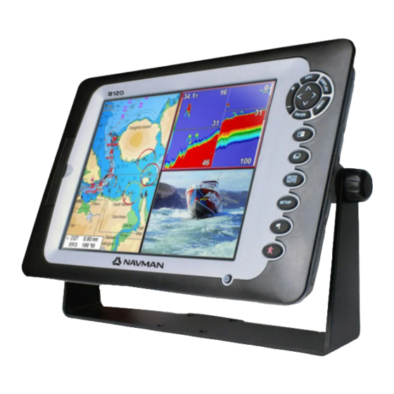
1-1 Overview The NAVMAN 8120 is a rugged, highly DSC/Buddy track functions require an integrated marine chartplotter and fishfinder. appropriate Navman DSC VHF radio to be It is easy to use and has a very large, easy installed. to read and use colour display. Complex... -
Page 7: Plug-In Cards
WARNING DANGER 1-3 Plug-in cards The 8120 can use two kinds of C-MAP™ CAUTION SD-Card plug-in cards: Handle plug-in cards carefully. Keep them Chart cards have chart details required in their protective cases when not plugged for navigating in a particular region. into the 8120. -
Page 8: Removing And Replacing The Display Unit
1-4 Removing and replacing the display unit Replacing the display unit If the 8120 is bracket mounted then it can easily be removed for security. 1 Plug the connectors into the back of the Removing the display unit: display unit: 1 Turn the 8120 off (see section 2-2) and put Match the connector’s colour to the the dust cover on. -
Page 9: Basic Operation
2 Basic Operation Overview of the keys Display – All windows and the data header/Compass Window – A part of the display in which a particular function is shown eg. The Chart window on a Chart + Sonar display. –... -
Page 10: Using The Keys
2-1 Using the keys In this manual: Changing data Press means to push the key for less than First press to move the highlight to a second. the data to change, then: Hold means to hold the key down. a) To change a tick box The internal beeper beeps when a key is means On or Yes pressed (to adjust the beep volume, see... -
Page 11: Turning On And Off / Auto Power
2-2 Turning on and off / auto power Turning on manually Auto power If the Instrument is not wired for auto power, If the Instrument is wired for auto power (see press to turn the unit on. If necessary, section 18-4), then: adjust the display to be easy to read (see •... -
Page 12: Man Overboard (Mob)
2-4 Man overboard (MOB) The MOB feature saves the boat’s position If the NMEA output (autopilot) is on, the CAUTION and then navigates back to this point. Instrument asks if the autopilot is active. Select: WARNING No: Use the Instrument to manually MOB will not work if the Instrument does navigate to the destination MOB DANGER... -
Page 13: The Main Windows
2-7 The main windows To show one of the main windows full-size, press and select the window. DISPLAY Note 1 The windows available depend on the optional sensors and instruments that are installed (see section 1-1). 2 Set up commonly used windows as favourites and press to switch between windows (see section 2-7-2). - Page 14 To show one of the other windows full- , select More... and screen, press DISPLAY select the window. Press to return from one of these windows to the previous window. 8120 Installation and Operation Manual...
- Page 15 2-7-1 Multi window displays Deleting a window from the display The 8120 can show up to four windows at once, for example Chart, Sonar, Gauges and 1 Press until the window you want to Video: delete has a red border. 2 Press and select Delete window.
- Page 16 2-7-2 Favourite displays Deleting a favourite display from the list The 8120 has a list of commonly used displays, called favourite displays. There can 1 Press and select Favourites. SETUP be up to six favourite displays. 2 Highlight the display to delete, press MENU Each display can have one or more windows and select Delete.
- Page 17 2-7-3 Data header Tip: If all fields in a line are None then the line will not be displayed and the data header will The displays can show data at the top, called take less space on the display. the data header. 5 Press Tip: The data header will change when you select another display.
-
Page 18: Navigation: Chart
3 Navigation: Chart The chart window shows the chart, the boat’s position course and navigation data. 3-1 Introduction to navigating The Instrument has two ways of navigating, going straight to a point or following a route. 3-1-1 Navigating to a point When the Instrument is navigating to a point, the chart and highway windows show navigation data:... - Page 19 3-1-2 Going to a waypoint or to a point on the To create waypoints before creating the route, see section 5-2-1. chart To create a route, see section 6-2-1. A waypoint is a position that you can set on Starting a route from the chart window: the Instrument chart, for example a fishing spot or a point on a route (see section 5).
-
Page 20: Chart Window
3-2 Chart window To go to the Chart window: and select Chart Press DISPLAY A typical chart window shows: A Data header. To turn the data off or on Note: or to change what data is displayed (see To change the types of information displayed section 2-7-3) on the chart, see section 17-2. - Page 21 3-2-1 Chart modes 36° 29.841’ N or S Latitude CAUTION 175° 09.012’ E or W Longitude The Chart has two modes: Centre on boat mode WARNING To switch to centre on boat mode in the chart When reading the boat position, make window, press .
-
Page 22: Distance And Bearing Calculator
3-2-5 Finding a chart symbol 3-2-6 Perspective view To find and display a chart symbol: Perspective view shows the chart from an angle instead of from straight above. To turn and select Find. 1 Press MENU perspective view on or off, press and set MENU 2 Select the type of symbol: Waypoints,... -
Page 23: Projected Course
3-4 Projected course If Projected course is turned on, then the Instrument will display the projected position based on the course over ground (COG), speed and a specified time. To turn Projected course on and off and to set the time, see section 17-2. -
Page 24: Video Window
4 Video window The video window shows a picture from a Changing the video picture video device, such as a camera. The video Press to zoom in window requires a video device to be installed. To select the video window, press and select Video. -
Page 25: Navigation: Highway Window
5 Navigation: Highway window The highway window has a bird’s eye view of the boat’s course to a destination: To go to the Highway window, press DISPLAY select More, then select Highway. The highway window shows: A Optional data header (see section 2-7-3) B Optional compass (see section 2-7-4) C Destination waypoint D Boat’s plotted course to destination... -
Page 26: Waypoints Window
6-1 Waypoints window To go to the waypoints window, press DISPLAY select More, then select Waypoints. The waypoints window is a list of the waypoints that have been entered, each with waypoint symbol, name, latitude and longitude, distance and bearing from the boat, type and display option. - Page 27 6-2-4 Displaying a waypoint on the chart 6-2-6 Deleting all waypoints This goes to the chart window, and shows 1 In the waypoints window and press MENU and select Delete all. the selected waypoint at the centre of the window. 2 Select Yes to confirm.
-
Page 28: Navigation: Routes
7 Navigation: Routes A route is a list of waypoints that the boat The Instrument can navigate along a route in can navigate along. Routes can be created, either direction. Waypoints on the route can changed and deleted. be skipped. The Instrument can have up to 25 routes. - Page 29 ii A waypoint is created with a default Tip: The distance and bearing calculator can also be used to enter a course and save it name. to save this waypoint press ENTER as a route (see section 3-3). to edit the waypoint refer to 5-2-7 B.
- Page 30 7-2-2 Editing a route 7-2-4 Deleting a route Editing a route from the chart 1 In the routes window, press highlight the route to delete. Press 1 In the routes window, select the route to MENU and select Delete. edit. Press and select Edit on chart.
-
Page 31: Satellites
GPS receiver better than 10 m (33 ft) for 95% of the time. A GPS antenna can receive signals from the Navman GPS units have a sensitive GPS satellites when it is almost anywhere on 12-channel receiver, which tracks signals from earth. -
Page 32: Satellite Window
8-1 Satellite window The satellite window has information about A Status of GPS antenna, for example Acquiring, GPS fix, No GPS. If the GPS satellites and GPS position. the unit is in Simulate mode it displays To go to the satellite window, press DISPLAY Simulate (see section 2-6). -
Page 33: Interpreting The Display
The appearance of echoes displayed are • Fishing mode: Use this when fishing. affected by: The Instrument automatically adjusts its settings to compensate for water clarity • The Instrument settings (see sections 17-3, and to best display fish, the bottom and 8-5 and 8-6) other details. - Page 34 DANGER Strength of echoes CAUTION The colours indicate differences in the Planing hulls at speed produce air bubbles strength of the echo. The strength varies with and turbulent water that bombard the several factors, such as the: transducer. The resulting ultrasonic noise •...
-
Page 35: Single And Dual Frequency Fishfinding
Shadows Shadows are created around areas where the ultrasonic beam cannot ‘see’. These areas include hollows on the bottom or beside rocks and ledges, where the strong echoes returned off the rocks obscure the weak echoes of the fish and may also create a double bottom trace. See following for an example of the sonar window in such an environment. - Page 36 When to use Mixed The Mixed frequency combines the 200 kHz and the 50 kHz echoes on one sonar window, filling in detailed echoes in the centre of the sonar cone. When to use 50/200 kHz Operating the Instrument at both 50 kHz and 200 kHz simultaneously on a split window can be very useful when operating in shallow to medium water, typically less than...
- Page 37 Comparison of the same fish scenario displayed at different frequencies: 1 minute ago 30 seconds ago 50 kHz display 200 kHz display 200/50 Khz display Mixed display 8120 Installation and Operation Manual...
-
Page 38: Fish Detection And Display
There are many reasons why fish arches may Fish symbols not be seen. For example: The Instrument uses NAVMAN’s SBN II • Poor transducer installation (see Transom technology to analyse sonar echoes and Transducers Installation Guide). -
Page 39: Range
• It is difficult to get fish arches in shallow • Wave motion may result in distorted fish water as the transducer sonar beam is arches. very narrow near the surface and fish do not stay within the beam long enough to display an arch. -
Page 40: Gain And Threshold
9-6 Gain and threshold Gain and threshold settings control the Changing mode amount of detail displayed on a sonar The Instrument has three operating modes, In window: Cruising and Fishing modes, the Instrument Gain: The gain of the sonar receiver. The automatically adjusts gain and threshold for gain should be high to display good detail, good performance. -
Page 41: Sonar Fishfinding: Windows
10 Sonar fishfinding: Windows If the window is split, adjust the split ratio if To show the Sonar window, press , then DISPLAY select Sonar. required: 1 Press and select Sonar window split. There are five kinds of sonar window. To use a MENU , select Sonar splits, window, press... -
Page 42: Sonar Zoom Window
10-2 Sonar Zoom window A Divider line B Depth line marks the centre of the zoomed area C Zoom bar D Zoom section E Sonar history The window shows the sonar history on the right and the zoomed section on the left. The zoom bar on the far right shows the area of the history that is magnified in the zoom section:... -
Page 43: Sonar Bottom Window
10-3 Sonar Bottom window The window shows the sonar history on the right and the bottom signal as a flat trace in the centre of the zoom section on the left. The flat trace make it easy to compare the echo strengths shown in the bottom signals. -
Page 44: Sonar A-Scope Window
10-5 Sonar A-Scope window A, B, C The strengths of echoes being received now from different depths - the longer the horizontal line the stronger the signal: A Unwanted noise echoes. B Echoes from fish and the bottom C The strongest echo, usually from the bottom D A vertical line showing the threshold, the weakest echo to display on the sonar... -
Page 45: Gauges Window
11 Gauges window Selecting a Gauges layout The Gauges window shows boat data, such as water speed, as analog gauges. To select the The Gauges window can show one of four Gauges window, press , select More, then gauge layouts. To select a layout from the DISPLAY select Gauges. -
Page 46: Fuel Functions And Display
13 Fuel functions and display The Fuel functions require optional fuel sensors to be installed. 13-1 When you add or remove fuel B When you part fill the tank When you add or remove fuel in a boat with no SmartCraft fuel tank level sensors, 1 Before adding fuel, go to the fuel window you must tell the Instrument, otherwise and write down the value of Remaining,... -
Page 47: Fuel Window
13-2 Fuel window To go to the Fuel window, press , select DISPLAY Other, then select Fuel. The window is different if engine RPM is available (requires SmartCraft or diesel sensors to be installed): The Fuel window shows Used The fuel used during a trip. When you want to start measuring how much fuel is used, press , select Fuel and select Clear used. -
Page 48: Fuel Consumption Curves
13-3 Fuel consumption curves A fuel consumption curve is a powerful 6 The Instrument then asks you to set the tool for assessing your boat performance in throttle to achieve a target RPM. For a twin different conditions and for helping you to engine boat set both engines to about run at the most economical speed for the the target RPM. - Page 49 E Blue marker: the fuel consumption now. b More information about fuel consumption This marker is below the blue curve, curves is available in Navman’s Diesel flow showing that the fuel consumption now at sensors installation and operation manual. this RPM is better than when you recorded Displaying a curve the curve.
-
Page 50: Tides Window
CAUTION 14 Tides window WARNING The tides window is available on Chart cards. 3 A list of tide stations are displayed. Select The tides window shows tide information at a the tide station to display. The chart DANGER tide station for the selected date. redraws with the tide station centred. -
Page 51: User Card Window
15 User card window A user card is an optional plug-in card that CAUTION can store data files (see section 1-3). There are three types of files: waypoints, routes or WARNING a track. To go to the user card window, press DISPLAY DANGER select Other, then select User card. -
Page 52: Dsc/Buddy Track Windows
MENU 2 Select sort by Name, Type or Time. 16 DSC/Buddy track windows Buddy track requires an optional Navman DSC VHF radio to be installed. Buddy track tracks other boats which have DSC radios connected to their GPS receivers by NavBus and are in VHF range. -
Page 53: The Windows
16-1 The windows Distress Poll Buddy track Boats that have sent DSC distress Boats you have manually Buddy boats from your DSC radio. messages and their positions. polled on the VHF radio, and The radio regularly calls the boats their position at that time. and updates their positions. -
Page 54: Using The Windows
16-2 Using the windows Displaying a boat on the chart 1 Press to select a boat. and select Display. The 2 Press MENU Instrument switches to chart window, with the selected boat position in the middle (see Boat positions above). Going to a boat 1 Press to select a boat. -
Page 55: Setting Up The 8120
17 Setting up the 8120 The 8120 has a number of advanced features which are set up through the setup menu. We recommend that you become familiar with the operation of the unit using the default settings before making any changes in these menus. - Page 56 Setup option menus Factory default settings are shown. The setup data available will depend on the optional sensors and instruments installed. System (see 17-1) Chart (see 17-2) Sonar (see 17-3) General, Water, Land and Other submenus (17-2) GPS (see 17-4) Fuel (see 17-5) SmartCraft Track (see 17-6)
-
Page 57: Setup > System
Night mode sets the palette for all windows In the unlikely event of having to contact Normal palette, for daytime a NAVMAN dealer for service, quote the All windows have a palette optimised for software version number and date. night time. -
Page 58: Setup > Chart
17-2 Setup > Chart Palette Press once or more until the Setup MENU menu is displayed, then select Chart: Select the colour scheme for the LCD window. The options are: Normal Sunlight: Brighter colours, more visible in sunlight. Night: Reversed colours for night, to preserve night vision. - Page 59 NMEA datum offset and select Set. 4 Press MENU If you select a map datum other than WGS 5 Press to set the new map shift. 84, the map datum offset can be applied to The boat will now be displayed at its latitude and longitude coordinates sent on actual location.
- Page 60 General submenu Plotter mode Only scales available on the chart card can be displayed. If you press to select a chart scale which is not available, on the chart card, the chart win- dow will change to this scale but will only display the boat position and track (if enabled). The rest of the window is white with black crosshatch lines and no chart information is displayed.
-
Page 61: Setup > Sonar
17-3 Setup > Sonar then select Sonar: Press Fish sensitivity SETUP Selects the minimum strength fish echo that will be displayed as a fish symbol. Higher values will display more fish symbols. Digit size Use this to remove or change the size of the depth window on the sonar windows. -
Page 62: Setup > Gps
There is a choice of Auto, Short, power output conserves the battery and Medium or Long. The Auto setting is produces a clear display in shallow water. recommended. There is a choice of Auto, Low, Medium or High. The Auto setting is recommended. Pulse power This can be used to specify the power output of the transmitted ultrasonic pulse. - Page 63 Tank size ENTER Note: If the fuel calibration options appear Enter the capacity of the fuel tank. Navman to give erroneous readings after a while, first recommends measuring tank size by draining check that the fuel sensor has been installed...
-
Page 64: Setup > Track
This option is included for compatibility Off: The Instrument stops recording a with older units. For information, see your track. NAVMAN dealer. 1 to 5 (select a track number): The Delete track Instrument starts recording the boat’s The data in the track selected for Record (see course into the selected track. -
Page 65: Setup > Logs
17-7 Setup > Logs then select Logs: The values can be reset independently of Press SETUP each other. These log values are saved when the unit is turned off. Reset trip dist This resets the trip distance to zero. Reset total dist This option resets the total distance to zero. -
Page 66: Setup > Units
Symbol Alarm Beeper Alarm sounds when it is on and the: Arrival boat is closer to the destination or to a waypoint radius than the alarm trigger value Anchor alarm boat moves by more than the alarm trigger value boat moves off course by more than the CDI scale (see section 14-2) Danger boat comes closer to a danger waypoint than... -
Page 67: Setup > Comms
Instrument to other NAVMAN instruments. Select this if the instruments are connected using NavBus. NavBus Group Use this when a group of NAVMAN NMEA out instruments are connected together using NavBus, to specify a group of instruments NMEA is generally used with third party for backlighting, if required. - Page 68 Note: for accurate calibration: gives stable readings. The range is 1 to 30 seconds or Off (0). • The speed from a GPS receiver should be greater than 5 knots. Fuel • The speed from another paddlewheel See section 17-5, Calibrate. transducer should be between 5 and 20 Keel Offset knots.
-
Page 69: Setup > Time
17-12 Setup > Time once or more until the Setup Press 1 Select Local offset. MENU menu is displayed, then select Time: 2 Press to change the offset, then press ENTER Time format The options are 24 hour or 12 hour. Date format Local offset The options are dd/MMM/yy, MMM/dd/yy,... -
Page 70: Installation
If the cables supplied are too long, do not shorten the cable; instead coil the cable. Most cables can be extended with Navman extension cables. Do not fit more than one extension cable. 8120 Installation and Operation Manual... -
Page 71: Installation: What Else Comes With My 8120
18-1 Installation: What else comes with my 8120? Navman GPS 1240 Antenna GPS 1240 Antenna bottom cone GPS 1240 Antenna gasket GPS 1240 mounting kit Sun cover for display unit Note: Place over display when not in use Front Bezel... -
Page 72: Installation: Options And Accessories
18-2 Installation: Options and Accessories • Replacement paddle wheel. • C-MAP™ NT-MAX, NT+ or NT chart SD cards. • NAVMAN NavBus junction boxes simplify wiring, particularly if several instruments are connected. For more information, see the NavBus Installation Manual. Optional sensors and instruments... -
Page 73: Installation: The Display Unit
Sonar Transducer Video in Video Input (Analogue composite [NTSC- PAL]) Comms Not Used GPS NAVMAN 1240 GPS Antenna Fuel/Nav - NAVMAN Fuel TXD - Diesel Fuel TXD - Smartcraft Gateway Not Used Power/data cable... - Page 74 There are two mounting arrangements: Flush Mounting the 8120 Bracket Mounting the 8120 1. Attach the flush mounting template to An alternative to flush mounting the 8120 is the selected mounting position using to bracket mount the unit. This method has adhesive tape.
-
Page 75: Installation: Power/Data Cable
Instrument must add up the total fuel used (for example if Navman petrol/gasoline fuel sensors are installed or if SmartCraft is installed without fuel tank level sensors). Otherwise wire for basic power (for more information, see section 2-2). -
Page 76: Installation: Gps Antenna
Follow the instructions in section 18-11) or NMEA (see section 18-12). the manual supplied with the antenna. Fit an In this case, the Instrument does not need optional Navman extension cable if required. its own antenna. During setup, configure the Instrument for Note: the chosen antenna, see section 17-4. -
Page 77: Installation: Navman Petrol/Gasoline Sensors
Note: SmartCraft engines have fuel flow sensors, White Fuel sensor cable therefore Navman fuel sensors are not required as well. For dual engines, fit two kits. Wire the Instrument for auto power (see section 18-4). -
Page 78: Installation: Dsc Vhf Radio
18-9 Installation: DSC VHF radio Fit and set up the optional Navman DSC VHF radio following the instructions supplied with Black Power/data cable the radio. Orange During setup: a) on the radio, enter buddy boats required Blue b) on the Instrument, set NavBus to... -
Page 79: Installation: Other Navbus Instruments
18-11 Installation: Other NavBus instruments NavBus is Navman’s system for connecting instruments together to interchage data and Black Power/data cable share transducers. When instruments are Orange connected by NavBus: If the units, alarms or calibration are Blue changed in one instrument, then the... -
Page 80: Installation: Other Nmea Instruments
An autopilot requires APB, APA and VTG sentences (see section 17-10). For information on sending NMEA data to the Instrument, see your Navman dealer. During setup to send NMEA data to other instruments, set NMEA out to and specify the NMEA data to send (see section 17-10). -
Page 81: Appendix A - Specifications
COMMUNICATIONS (optional), loss of DGPS fix NavBus GPS NAVIGATION Connection to other NAVMAN instruments. Chart card: C-MAP™ SD Card (NT-MAX, NT+ or NMEA: NMEA 0183 ver 2 4800 baud Inputs from compatible instruments: User card: SD Card... - Page 82 385 mm (15.1 ") 78.5 mm(3.1 " ) 11.4 mm (0.45 ") List of datums Adindan Afgooye AIN EL ABD 1970 American Samoa 1962 Anna 1 Astro 1965 Antigua Island Astro 1943 ARC 1950 ARC 1960 Ascension Island 1958 Astro Beacon ‘E’ 1945 Astro DOS 71/4 Astro Station 1952 Astro Tern Island (Frig) 1961...
-
Page 83: Appendix B - Troubleshooting
NAVMAN. If the product must be sent into a manual. service centre for repair, it is essential to send in the transducer(s) at the same time. -
Page 84: Gps Navigation Problems
B-2 GPS navigation problems 2-1 No GPS fix or long time to get fix at 2-5 The time or date on satellite display is startup: wrong or off: a May occur occasionally if the antenna a No GPS fix. does not have a clear view of the sky. The b In simulate mode. -
Page 85: Sonar Fishfinding Problems
3-2 Flow indicates no fuel or low fuel: 3-4 Erratic Fuel Flow readings: a Check that the number of engines is set to a The fuel flow transducer may have been 1 (see section 17-5). mounted too close to the fuel pump or may be subject to excessive vibration. - Page 86 i Electrical noise from the boat’s engine or b The transducer may be in turbulent an accessory may be interfering with the water. Air bubbles in the water disrupt transducer(s) and/or the Instrument. This the echoes returned, interfering with the may cause the Instrument to automatically Instrument’s ability to find the bottom or decrease the Gain unless using Manual...
-
Page 87: Appendix C Glossary And Navigation Data
Appendix C Glossary and navigation data Air temp - Air temperature (requires Navman NavBus - A way of connecting NAVMAN 7200 VHF radio). instruments together to share data (see section 18-11). Alarm status - Shows the symbol (see section 17-8) for each alarm that is on. The... -
Page 88: Navigation Data
Navigation data The boat is sailing from the start to the destination and has moved off the plotted course from the start to the destination. Bearing to Destination: Bearing to the destination from the boat. BRG Bearing to cursor: Bearing to cursor from boat (cursor mode, see section 3-2-1) Course Deviation Indicator: When the boat is navigating to a point, the chart and highway windows show a parallel line on either side of the plotted course. -
Page 89: Appendix D Compliance Statements
Appendix D Compliance statements FCC Statement Note: This equipment has been tested and found to comply with the limits for a Class B digital device, pursuant to Part 15 of the FCC Rules. These limits are designed to provide reasonable protection against harmful interference in a normal installation. - Page 90 Lat 36° 48.404’S Made in New Zealand MN000444A D a t a h e l m 8120 I n s t a l l a t i o n a n d O p e r a t i o n M a n u a l...