Table of Contents
Advertisement
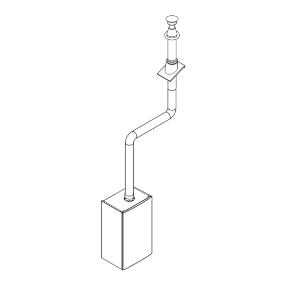
Flue Accessories & Fitting Guide
Ø 60/100 Flue Systems
Ø 80/125 Flue Systems
Ø 80/80 Twin Flue Systems
Plume Displacement Kit
READ THESE INSTRUCTIONS IN CONJUNCTION WITH THE BOILER
INSTALLATION INSTRUCTIONS BEFORE FITTING THE FLUE
© Baxi Heating UK Ltd 2011
(Ø 60/100 Flue Systems)
G U I D A N C E N O T E S
IMPORTANT NOTE: This document
will assist in the correct installation of
the various flue & chimney systems
described within. However, it is the
responsibility of the installer/Gas Safe
registered commissioning engineer to
ensure that the flue & chimney system
is fitted safely and in compliance with
the relevant standards and practices in
force in the country of installation.
Please leave these instructions with the
Installation & Servicing Instructions.
Advertisement
Table of Contents

Related Manuals for Baxi MULTIFIT Flue Systems

Summary of Contents for Baxi MULTIFIT Flue Systems
- Page 1 & chimney system is fitted safely and in compliance with the relevant standards and practices in force in the country of installation. Please leave these instructions with the Installation & Servicing Instructions. © Baxi Heating UK Ltd 2011...
-
Page 2: Important Notes
MAKING GOOD Where the flue system passes through an external wall the joint should ‘made good’ by use of suitable sealant or building materials and the flue trims supplied if required. page 2 © Baxi Heating UK Ltd 2011... - Page 3 Z2 Pitched Roof Terminal-Twin Flue (Z1 req’d) (Black) 720576301 Pitch Roof Flashing (Black) 25°/50° 5122151 Z3 Ridge Terminal (Brown) 720647101 Roof Cover Plate 246143 Z4 PDK - (Black) 720622901 Flat Roof Flashing (Black/Grey) 246144 Z4 PDK - (White) 720627001 page 3 © Baxi Heating UK Ltd 2011...
- Page 4 ! When the flue system is in place fully tighten all brackets systematically, ensuring that no parts are under any strain or tension and no dips where condensate can pool. page 4 © Baxi Heating UK Ltd 2011...
- Page 5 Do not direct the deflector upwards or downwards. NOTE: A terminal guard is still required when circumstances Flue Terminal dictate (B.S. 5440-1). DO NOT DIRECT THE FLUE DEFLECTOR TOWARDS A WALL. page 5 © Baxi Heating UK Ltd 2011...
- Page 6 80/125 Horizontal Flue Kit). Apply lubrication and ensure that the 80/125 adaptor is fully engaged in the boiler adaptor. Secure with the screws supplied with boiler. 80/125 Adaptor Securing Screw Boiler Adaptor page 6 © Baxi Heating UK Ltd 2011...
- Page 7 Please Refer to the Fitting Instructions supplied with the Kit. page 7 © Baxi Heating UK Ltd 2011...
- Page 8 120mm to Flue 300mm Clearance Zone Exhaust Duct 60mm View Air Duct Possible Air Terminal positions 100mm Outside Wall Exhaust Duct Air Exclusion Zone Exhaust Greater than 300mm Mini Terminal Clearances Fig. B page 8 © Baxi Heating UK Ltd 2011...
- Page 9 Badly Flue Pipe Do Not Damage Internal Seals with badly cut extensions Clean Leave 5mm clearance at Flue Pipe bottom of each joint Ø80 50mm Seal depth Twin Flue Extension/ Bend Connection page 9 © Baxi Heating UK Ltd 2011...
- Page 10 NOT outside !! 300mm Clearance* * The clearance around the air inlet must extend 300mm in all directions. Twin Pipe System with Air 300mm Duct Inlet in minimum Loft Space page 10 © Baxi Heating UK Ltd 2011...
- Page 11 Cut air duct to leave 170mm of exhaust duct protruding into the room of installation. Any precautionary measures must be removed prior to commissioning the boiler. page 11 © Baxi Heating UK Ltd 2011...
- Page 12 However, if any movement of the flue system inside the dwelling is suspected, the integrity of flue should be Terminal checked by performing a flue gas analysis at the boiler adaptor air sampling point. page 12 © Baxi Heating UK Ltd 2011...
- Page 13 The inlet of the PDK MUST be at least 300mm above ground or balcony level or any projection or ledge. A guard must be fitted where the inlet is below 2 metres. 500mm Min. page 13 © Baxi Heating UK Ltd 2011...
- Page 14 1 metre, each 45° bend to 0.5 metres. Graph Line A is suitable for Combi 24 Models System 12,15,18,24 Models Graph Line B is suitable for Combi 28,33,40 Models System 28,32 Models page 14 © Baxi Heating UK Ltd 2011...
- Page 15 Concentric 60/100 Flue (metres) Example 1 Flue Lengths - Not Permissible Concentric 60/100 Flue (metres) Example 2 Flue Lengths - OK Concentric 60/100 Flue (metres) Example 3 Flue Lengths - OK for A & B page 15 © Baxi Heating UK Ltd 2011...
- Page 16 All goods are sold subject to our standard Conditions of Sale which are available on request. MUL TIFIT A Registered Trademark of Baxi Heating UK Ltd (3879156) Brooks House, Coventry Road, Warwick. CV34 4LL Technical Enquiries 0844 871 1555 Website: www.baxi.co.uk...