Table of Contents
Advertisement
Code: 953449
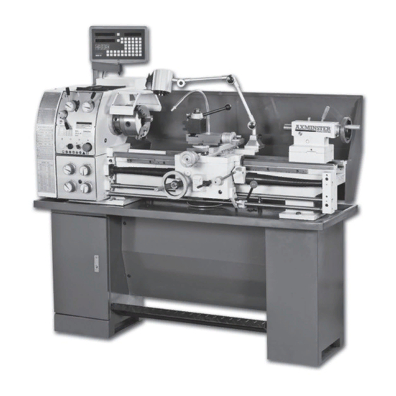
CQ6230A-2/910 Metal
Turning Lathe
A high specification, floor standing, heavy duty metal
turning lathe suitable for the keen model engineer, general
maintenance and small production facilities.
Featuring a high tensile cast iron, precision ground, induction hardened bed
for long term accuracy. A fully gear driven spindle runs on precision taper roller
bearings, with hardened and ground gears giving a speed range of 65 - 1,810rpm,
selectable via the headstock mounted levers and a choice of two motor drive belt
speeds. The spindle has the popular D1-4 quick lock chuck mounting, ensuring a
wide range of accessories can be fitted.
Axminster Tool Centre,
Unit 10 Weycroft Avenue, Axminster, Devon EX13 5PH
www.axminster.co.uk
Advertisement
Chapters
Table of Contents

Related Manuals for Axminster CQ6230A-2/910


Summary of Contents for Axminster CQ6230A-2/910
- Page 1 The spindle has the popular D1-4 quick lock chuck mounting, ensuring a wide range of accessories can be fitted. Axminster Tool Centre, Unit 10 Weycroft Avenue, Axminster, Devon EX13 5PH www.axminster.co.uk...
-
Page 2: Table Of Contents
OWNER’S MANUAL CONTENTS NOTE---------------------------------------------------------------------------------- LIMITED WARRANTY------------------------------------------------------------ 2 PASSPORT DATA----------------------------------------------------------------- 3 TEST PROTOCOL---------------------------------------------------------------- GENERAL DESCRITION OF THE MACHINE------------------------------ 7 GENERAL DATA-------------------------------------------------------------------- 7 BASIC TECHNICAL DATA-------------------------------------------------------- 9 DESCRIPTION FO THE MAIN UNITS---------------------------------------- 10 GEAR BOX--------------------------------------------------------------------------- 10 QUADRANT-------------------------------------------------------------------------- 10 FEED BOX--------------------------------------------------------------------------- 10 CARRIAGE GROUP--------------------------------------------------------------- 10 THREAD INDICATOR------------------------------------------------------------- 11 TAIL STOCK-------------------------------------------------------------------------- 11 RESTS--------------------------------------------------------------------------------- 11... -
Page 3: Note
OWNER’S MANUAL NOTE This manual has been prepared for the owner and operators of this lathe. Its purpose, aside from machine operation, is to promote safety through the use of accepted correct operating and maintenance procedures. Completely read the safety and maintenance instructions before operating or servicing the machine. -
Page 4: Passport Data
OWNER’S MANUAL PASSPORT DATA Model: Serial No.: Main el. motor: GEOMETRIC ACCURACY CHECKING The machine lathe guide way horizontality shall be checked in longitudinal and transverse direction towards the machine axis by the help of level with an accuracy up to ±0.02/1000 mm and ± 0.04/1000 mm. before starting any accuracy measurement. -
Page 5: Test Protocol
OWNER’S MANUAL TEST PROTOCOL Diagram of measuring method Inspection item Tolerance Data Alignment Full travel longitudinal bed slide 0.25 (+) ways in vertical place Parallelism 1000:0.06 transverse direction Parallelism tailstock longitudinal motion of carriage. In vertical plane a. 500:0.03 horizontal b. - Page 6 OWNER’S MANUAL Diagram of measuring method Inspection item Tolerance Data Spindle center run out 0.02 Parallelism center line of tailstock spindle to longitudinal motion of carriage In vertical plane 200:0.03 In horizontal plane 200:0.03 Difference center height between 0.06 headstock and tailstock (tailstock upward) Spindle a.
- Page 7 OWNER’S MANUAL Parallelism of top slide 0.04 to spindle center line Lead screw 0.03 action Accuracy of outside round cutting a. Roundness a. 0.015 b. Cylindricity 300:0.04 Flatness of the face for 0.015 (for Ø finishing cutting 160mm) (concave) Precisely thread cutting on work piece between tow centers...
-
Page 8: General Descrition Of The Machine
OWNER’S MANUAL 1. GENERAL DESCRIPTION OF THE MACHINE GENERAL DATA 1.1. MAIN ASSEMBLIES (See Fig. 1a) 1. Bed way 13. Leads crew (with Guard) 2. Headstock 14. Feed rod 3. Feed box 15. Switch rod 4. Carriage box 16. Tool holder 5. - Page 9 OWNER’S MANUAL Page - 8 -...
-
Page 10: Basic Technical Data
OWNER’S MANUAL 1.2. BASIC TECHNICAL DATA Form 1 CQ6230 SERIAL C0632C Max swing over bed Ø 300 mm Ø 320mm Max swing over gap Ø 430 mm Ø 450mm Max swing over cross slide Ø 180 mm Ø 180mm Distance between centers 900 mm / 750 mm 1000 mm Taper of spindle bore... -
Page 11: Description Fo The Main Units
OWNER’S MANUAL 2. DESCRIPTION OF THE MAIN UNITS GEAR BOX The gear box is mounted on the machine corp. the rotation motion to this gear box is transferred through V-belts and belt pulley from an el. motor mounted on the guide way. QUADRANT The quadrant is destinated to transfer the motion from the gear box to the feed box through some change gears. -
Page 12: Thread Indicator
OWNER’S MANUAL transverse direction. This movement may be effected automatically or manually. D. When short cones have to turned by hand, the cross piece may be swiveled at 90° towards the lower slide in both directions and be fixed in the required position by the help of suitable bolts and nuts. -
Page 13: Machine Installation
OWNER’S MANUAL 3. MACHINE INSTALLATION TRANSPORTATION The machine is transported in a special wooden case (or with foot stands separately packed in carton), being fixed to the base of the case or slide by suitable bolts. Some of the accessories are mounted on the lathe well fixed and the other packed in a separate box or directly fixed on the case base. -
Page 14: Connection To The El. Supply Source
OWNER’S MANUAL by concrete with a thickness from 200 to 300 mm according to the soil strengthness. The unpacked machine is lifted by crane according to the specified method and after the anchor and leveling bolts are in place, lower the foundation so that the anchor bolts enter into the respective holes. - Page 15 OWNER’S MANUAL After one-hour operation of the machine, check the oil level in the tanks and if necessary add the required quantity. After two shifts operation of the machine, check the play of the V-belts. Page - 14 -...
-
Page 16: Machine Service
OWNER’S MANUAL 4. MACHINE SERVICE LUBRICATION The trouble-free operation on the lathe depends on its careful servicing. Of special importance is the regular lubrication of all machine-operating parts with the recommended lubricants. These lubricants are listed in the Fig. 3a 3b 3c –Lubricating System. -
Page 17: Recommended Lubricants
OWNER’S MANUAL RECOMMENDED LUBRICANTS For normal and other climatic conditions Form 2 Lubricating Lubricating Assembly Lubricant Lubricating interval point method Oil replacement: --for Gears the first time—after 10 bearings. days operation of the Spindle front lathe—for the second Headstock bearing. bath—by Machine oil time—after... -
Page 18: Machine Operation
OWNER’S MANUAL 5.MACHINE OPERATION PUTTING INTO OPERATION After performing the previous instruction, the machine is ready for operation, the connection to the el. supply source is effected by the help of the main interrupter. Turning on of the control lamp shows that the machine is connected to the el. - Page 19 OWNER’S MANUAL All the quadrant setting and drums / handle different position are shown in nameplate for threads and feeds. I & III TYPE FEEDBOX: Select handle 4 for feeding or threading. Handle / drums 5,6,21 are for controlling the speed of feedbox. II TYPE FEEDBOX: Push handle 4 inside then move left or right to select feeding or threading, drawing back then move left or right for controlling the feed rate and size of the...
- Page 20 OWNER’S MANUAL Adjust the nut gap on the carriage see Fig. 7. Rotate the p.1 on the nut to satisfied saddle moving and required travel. Chuck and faceplate mounting see Fig. 8. The connection between spindle and chuck or faceplate is made by D-Cam lock structure. When mounting, put the three pull pins of chuck or faceplate into the three holes on the spindle face end, then turn the three cams with the aid of square head wrench, when turning the cams clockwise, the chuck or faceplate will be locked, when turning...
-
Page 21: Fretted Parts
OWNER’S MANUAL FRETTED PARTS Form 3 Name Material Mount Note Feeding nut ZQSn6-6-3 CQ6230-5104 Half nut ZQSn6-6-3 CQ6230-4003 Page - 20 -... -
Page 22: Mechanism's Adjustment
OWNER’S MANUAL 6. MECHANISM’S ADJUSTMENT All the mechanisms are adjusted and tested in the producer’s plant. After a prolonged exploitation, some of the mechanisms have to be readjusted because of the wearing off of the friction surfaces. The adjustment and setting of the different mechanisms shall be effected after each machine repair too. -
Page 23: Machine Care And Maintenance
OWNER’S MANUAL 8. MACHINE CARE AND MAITENANCE Lathes are highly accurate machine tool designed to operate around the clock if properly operated and maintained. Lathes must be lubricated and checked for adjustment before operation. Improper lubrication or loose nuts and bolts can cause excessive wear and dangerous operating conditions. -
Page 24: Transmission System & Parts
OWNER’S MANUAL TRANSMISSION SYSTEM & PARTS (See Fig.11) Form.4 No. of Modulus Parts Pressure Parts Kinds Material Notes teeth of angle thread pitch Gear 20° 2013 Gear 20° 2018 Gear 20° 2019 Gear 20° 2021 Gear 20° 2020 Gear 20° 2022 Gear 20°... - Page 25 OWNER’S MANUAL Continuing Gear M2.25 20° 3009B Gear M2.25 20° 3016C Gear M2.25 20° 3014C Gear M2.25 20° 4028 Rack M2.25 20° Lead Single 8T.P.lor 3mm 29° or 30° screw thread Single Halfnut ZQSn6-6-3 thread Single Worm 20° thread Worm 20°...
- Page 26 OWNER’S MANUAL Gear M1.25 20° 3039C Gear M1.25 20° 3039C Paired 127(120) M1.25 20° 3078C Gear Page - 25 -...
- Page 27 OWNER’S MANUAL Page - 26 -...
-
Page 28: Bearing Distribution
OWNER’S MANUAL BEARING DISTRIBUTION (See Fig.12) Form 5 TYPE Name Specification Installation 60104 Ball bearing single row 20×42×12 60105 Single row ball bearing with shield 25×47×12 Single row ball bearing with shield 20×52×15 Headstock Single row ball bearing 20×42×12 Single row ball bearing 25×17×12 Single row ball bearing 20×47×14... - Page 29 OWNER’S MANUAL PARTS DRAWING & PARTS LIST BE SUBJECT TO ALTERATION WITHOUT NOTICE CONTENTS BED ASSEMBLY------------------------------------------------------------------ 28 HEAD STOCK -------------------------------------------------------------------- GEAR BOX ------------------------------------------------------------------------ GEAR BOX -I----------------------------------------------------------------------- 35 GEAR BOX -II--------------------------------------------------------------------- GEAR BOX -III-------------------------------------------------------------------- APRON------------------------------------------------------------------------------ 44 COMPOUND REST--------------------------------------------------------------- 48 SADDLE---------------------------------------------------------------------------- 10 TAIL STOCK----------------------------------------------------------------------- 11 CHANGE GEAR ----------------------------------------------------------------- 12 CONTROL SWITCH ASSEMBLY-------------------------------------------- 13 BED AND DRIVE ASSEMBLY-------------------------------------------------...
- Page 30 OWNER’S MANUAL 18 PROTECTING COVER--------------------------------------------------------- 19 GUARD----------------------------------------------------------------------------- Page - 29 -...
-
Page 31: Bed Assembly
OWNER’S MANUAL BED ASSEMBLY BED ASSEMBLY NAME NOTE NAME NOTE Lathe bed 10047 Screw M6×15 Screw M12 ×40 5×20 Rack gear 1009 Rack gear 1011 Page - 30 -... -
Page 32: Head Stock
OWNER’S MANUAL HEAD STOCK Page - 31 -... - Page 33 OWNER’S MANUAL HEAD STOCK NAME NOTE NAME NOTE Spindle 2034 Circlip Lock pin 2035 Gear 2022 Spring 0.6×4×22 Gear 2020 Screw M8×16 Gear 2021 Cover 2038 Circlip Oil seal 2006 Bearing 6104 Bearing D7212 Cover 2009 Gear 2031 Oil seal 2009A Gear 2030...
- Page 34 OWNER’S MANUAL NAME NOTE NAME NOTE 5×80 Headstock 2033 C5×24 4×24 Gear 2019 Oil seal 16×2.4 Gear 2018 Shaft 2046 Gear 2013 Shaft arm 2042 Circlip 4×24 Bearing Circlip Circlip Shifter 2041 Cover 2012B 5×16 Oil seal D25×40×10 Handle 2058 Screw M6×20 Boss...
-
Page 35: Gear Box
OWNER’S MANUAL GEAR BOX Page - 34 -... - Page 36 OWNER’S MANUAL GEAR BOX NAME NOTE. NAME NOTE. Oil Cup Boss 2057 Circlip 5×40 Gear 3015 Gear Box 3001 Bushing 3016 Screw M8×8 Washer 3024 Spring 1×4.5×7 Gear 3023 Sted Ball Shaft 3022 Screw M10×30 5×10 Spring washer Cover 3031 Feed Rod 1006 Screw...
- Page 37 OWNER’S MANUAL NAME NOTE NAME NOTE Washer 3021 Gear 3018 Gear 3027 Washer 3017 Shaft 3020 Gear 3012 5×75 Gear 3011 3042 Gear 3010 3043 Gear 3009 3014 Gear 3008 Shaft 3003 Gear 3007 5×18 Gear 3006 3002 Gear 3005 Screw M6×5 Gear...
-
Page 38: Gear Box -I
OWNER’S MANUAL GEAR BOX-Ⅰ Page - 37 -... - Page 39 OWNER’S MANUAL GEAR BOX-Ⅰ NAME NOTE NAME NOTE Oil Cup Gear 3026C Screw M6×12 Gear 3007C Cover 3034B Washer 3008C Oil seal 3035C Circlip Bearing Bearing 5×13 Gear 3009B Shaft 3041B C5×40 6×90 Shaft 3019C Gear 3005B Shaft 3004B Washer 3066B 5×35 Screw...
- Page 40 OWNER’S MANUAL NAME NOTE NAME NOTE Screw M6×12 Shifter 3049B 5×25 Cover 3061B Spring washer Screw M8×16 Screw , 10×30 Oil window Screw M6×12 Shifter 3062B Washer 6×32×5 Shifter arm 3063B Bushing 3024C Boss 3057C Gear 3016C Shaft 3056C Screw M6×16 Oil seal 16×2.4...
-
Page 41: Gear Box -Ii
OWNER’S MANUAL GEAR BOX-Ⅱ Page - 40 -... - Page 42 OWNER’S MANUAL GEAR BOX-Ⅱ NAME NOTE NAME NOTE Oil Cup Bearing Screw M6×12 Gear 3009B Cover 3034B C5×40 Oil seal 3035C Shaft 3019C Bearing Shaft 3004B 5×13 5×35 Shaft 3041B Circlip 6×90 Gear 3006C Gear 3005B 5×25 Washer 3066B Gear 3018C Screw M6×8...
- Page 43 OWNER’S MANUAL NAME NOTE NAME NOTE Screw M6×16 3048D Shaft 3015C Bulb 3052D Oil seal 22×2.65 Oil seal 8.5×1.8 Gear 3014C Shaft 3056D Cover 3022F 3079D Oil seal 3086D Spring Screw M6×25 Ball Shaft 3013D Spring 1×5×14 Oil seal Screw M8×5 Screw M16×1.5...
-
Page 44: Gear Box -Iii
OWNER’S MANUAL GEAR BOX-Ⅲ Page - 43 -... - Page 45 OWNER’S MANUAL GEAR BOX- III NAME NOTE NAME NOTE Oil cup Gear 3003B Screw M6×12 Washer 3030B Cover 3034B Gear 3002B Oil seal 3035C Gear 3026C Bearing 89103 Gear 3007C 5×13 Washer 3008C Shaft 3041B Circlip 6×90 Bearing 89103 Gear 3005B Gear 3009B...
- Page 46 OWNER’S MANUAL NAME NOTE NAME NOTE Fascia 3060E Screw M8×15 Oil seal 3071D Screw M6×10 Cover 3059D Position piece 3012D Cover 3042C Support 7003B Oil seal 3070C Screw M4×20 Gear box 3001C Shaft 3011D Screw M6×12 Gear rack 3050C 5×25 Gear rack 3049C Spring washer...
- Page 47 OWNER’S MANUAL APRON-LEFT Page - 46 -...
- Page 48 OWNER’S MANUAL APRON-RIGHT Page - 47 -...
-
Page 49: Apron
OWNER’S MANUAL APRON-LEFT OR APRON-RIGHT NAME NOTE NAME NOTE Bushing 4026 Leaf spring 4037 Gear 4029 Shaft 4015 5×30 Gear 4012 Space 4027 5×33 Gear shaft 4028 Gear 4013 Worm am 4008 Gear 4014 Worm 4009 Bushing 4016 Flat key B5×36 Apron case 4001... - Page 50 OWNER’S MANUAL NAME NOTE NAME NOTE Worm gear 4017 3022 Half nut Oil window M6×25 house Screw M5×33 Screw M5×35 Washer Ø6 half nut 4002 Screw M6×10 Screw 4003A1 Screw M6×6 Screw M6×15 Limit block 4043 Safety shifter 4025 Thread dial 4006 Shaft 4024...
-
Page 51: Compound Rest
OWNER’S MANUAL COMPOUND REST Page - 50 -... - Page 52 OWNER’S MANUAL COMPOUND REST NAME NOTE NAME NOTE Handle 5010 4×8 Boss 5009 Bearing 8101 Collar 5008 Scale 5026A2 Screw M10×45 Rivet 2×4 Tool post 5005 Screw M6×25 Shaft 5006 Bracket 5013 5003 Bearing 8101 5004 Index ring 5014A3 Spring 1.2×4.8×8 Hand wheel 5016A...
-
Page 53: Saddle
OWNER’S MANUAL SADDLE Page - 52 -... - Page 54 OWNER’S MANUAL SADDLE NAME NOTE NAME NOTE Saddle 5101 Press plate 5131 Screw M5×132 Press plate 5116 Wipper 5108 5×20 Cover 5106 Press plate 5129 Screw M3×8 3×20 Press plate 5130 Index ring 5124A3 Press plate 5110 Leaf spring 4037 Wipper 5109 Hand wheel...
-
Page 55: Tailstock
OWNER’S MANUAL TAIL STOCK TAILSTOCK NAME NOTE NAME NOTE Handle 4033 6012 Lever 4032 Quill 6013 Tail stock 6001 Washer Lock screw 6022 Hand wheel 6005 Handle 6021 Leaf spring 4037 Shaft 6017 Index ring 6010 Handle 6004 Screw M6×16 5×30 Bracket 6011... -
Page 56: Change Gear
OWNER’S MANUAL CHANGE GEAR CHANGE GEAR NAME NOTE NAME NOTE Screw M6×12 Circlip Washer 2003 Washer Gear 2002C Screw M10×45 C5×8 Washer 3037A Gear 3039C Washer 3035 5×18 Gear 3038C Washer 3034B Bearing Change gear 3076C Collar 3033 Change gear 3075C Quadrant 3043B... -
Page 57: Control Switch Assembly
OWNER’S MANUAL CONTROL SWITCH ASSEMBLY CONTROL SWITCH ASSEMBLY NAME NOTE NAME NOTE Guide screw 1005B 4×20 1006B Bracket 1014B Bracket 1012 Spring 1.2×8.10 6×65 Screw M6×15 Screw M8×60 Bracket 1015B Oil cup Handle ball M10×32 Ball Handle 1016 4×20 Circlip Bushing 1035B Spring... -
Page 58: Bed And Drive Assembly
OWNER’S MANUAL BED AND DRIVE ASSEMBLY BED AND DRIVE ASSEMBLY NAME NOTE NAME NOTE Cover 1021 Screw M6×8 Screw 1002 Motor 1001 Spacer Ø8 Trestle 1024 Screw Washer 1013 Screw Screw M8×45 8×40 Screw M8×30 Pulley 1003A5 Page - 57 -... -
Page 59: Special Accessories
OWNER’S MANUAL SPECIAL ACCESSORIES Page - 58 -... - Page 60 OWNER’S MANUAL SPECIAL ACCESSORIES--BASE PART NAME NOTE NAME NOTE Chip guard 1023 Back plate 8601 Screw M6×16 Oil pan 1022 Right bracket 8603 Left cabinet 8400 Right cabinet 8500 Left bracket 8602 Screw M6×16 Screw M6×16 SPECIAL ACCESSORIES--BRAKE PART NAME NOTE NAME NOTE...
- Page 61 OWNER’S MANUAL SPECIAL ACCESSORIES--COOLING PART NAME NOTE NAME NOTE Coolant pipe Filter 9203 Screw M5×12 Pipe 9204 Pipe connecting 9206 Hooping Washer 9207 Pine 16×1000 Bracket 9208 Coolant X6121-06011 Shaft Screw M5×10 Screw M8×35 Pipe M16×15 Coolant pipe Metal pipe 8×1800 Coolant pipe Cover...
-
Page 62: Steady Rest
OWNER’S MANUAL STEADY REST STEADY REST NAME NOTE NAME NOTE Knob 8205 Hex screw nut Screw M6×8 Screw M6×25 Collar 8207 Base body 8201 Pressing lever 8206 Hex screw nut Pressing collar 8208 Washer Pressing base 8209 Pressing plate 6020 Upper body 8202 Square ad bolt... -
Page 63: Follow Rest
OWNER’S MANUAL FOLLOW REST FOLLOW REST NAME NOTE NAME NOTE Screw M6×6 Screw M6×10 Knob 8205 Hex screw nut Collar 8207 Screw M6×16 Pressing lever 8206 Body 8201 Pressing collar 8208 Bolt M8×40 Pressing base 8209 Page - 62 -... -
Page 64: Position Device
OWNER’S MANUAL POSITION DEVICE POSITIONING DEVICE NAME NOTE NAME NOTE Knob 8705 Body 8703 M3×6 Indictor 8707 Guide screw 8706 Screw M6×10 Pressing plate 8704 Screw M6×12 Page - 63 -... - Page 65 OWNER’S MANUAL PROTECTING COVER PROTECTING COVER NAME NOTE NAME NOTE Shaft 8902 Screw M6 ×16 Protecting cover 8903 Switch box 8901 M4 ×12 Screw M6× 45 Page - 64 -...
- Page 66 OWNER’S MANUAL GUARD GUARD NAME NOTE NAME NOTE Left box 1120 Apron 4000 Down board 1118 Bracket 1012 Up board 1117 Gear Box 3000 Right box 1110 Page - 65 -...
- Page 67 OWNER’S MANUAL Distributor: Page - 66 -...