
Related Manuals for Axminster AH-1218


Summary of Contents for Axminster AH-1218
- Page 1 Code 505020 Code 505021 AH-1218 & AH-1218VS Woodturning Lathes Axminster Tool Centre, Unit 10 Weycroft Avenue, Axminster, Devon EX13 5PH axminster.co.uk...
-
Page 2: Declaration Of Conformity
Index of Contents Index of Contents Declaration of Conformity What’s Included General Instructions for 230V Machines Specification Assembly 05-06-07 Illustration and Parts Description 08-09-10 Operating Instructions 11-12-13 Removing Drive/Live Centres Maintenance Parts Breakdown Parts List 16-17-18 Wiring Diagram Declaration of Conformity Copied from CE Certificate Manufactured by Laizhou Chunlin Machinery Co. -
Page 3: What's Included
User Manual Optional Accessories Quantity Item Part 1 No Bed Extension with Hex screws, washers (code 503035) AH-1218 Wood Lathe (code 505020) AH-1218VS Wood Lathe (code 505021) Axminster 4 Prong Drive Centre (code 340106) Axminster Standard 60˚ Live Centre (code 340203) -
Page 4: General Instructions For 230V Machines
General Instructions for 230V Machines Do not work with cutting tools of any description if Work Place/Environment you are tired, your attention is wandering or you are being subjected to distraction. A deep cut, a lost Make sure when the machine is placed that it sits fingertip or worse;... -
Page 5: Specification
Specification Model AH-1218 Model AH-1218VS 505020 505021 Code Code Rating Hobby Rating Hobby Power 600W (230V) Power 550W, 230V (5) 500-3,150 rpm (2) 500-2,040 and 1,000-4,080 Speed Speed Spindle Taper Spindle Taper Spindle Thread 1” x 8tpi (Ref T04M) Spindle Thread 1”... - Page 6 Assembly Fig 05 Tool Holder Locate the tool holder (I) the two Phillips screws and washers. (see fig 3) Place a washer over the screws and screw them into the two pre-drilled holes below the headstock, (see fig 4). NOTE: There are also two pre-drilled holes under the tailstock if you wish to mount the tool holder there.
- Page 7 Assembly Fig 07 Fig 10 Hex screw Fig 08 Fig 11 Fig 09 Fig 12...
-
Page 8: Illustration And Parts Description
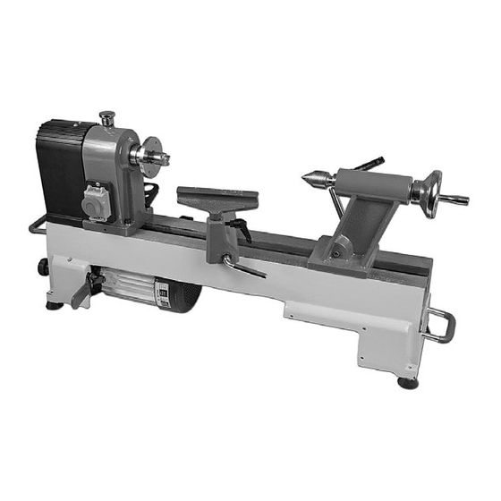
Illustration and Parts Description Headstock cover AH-1218 Headstock Faceplate Tailstock 150mm Tool rest Lathe bed Carrying handle Banjo arm Lower pulley NVR switch door lock assembly Motor assembly Index lock pin AH-1218VS Rubber foot Index ring 4 Prong drive centre 60˚Live centre... - Page 9 Power cable hooks Tool holder Fig 13 Fig 14 (ON) ( I ) and (OFF) (O) buttons AH-1218 Emergency stop shroud, slap the shroud down to stop the lathe in an emergency Fig 15 Fig 16 AH-1218VS Control box Speed control dial...
- Page 10 Illustration and Parts Description Fig 17 Fig 18 Index pointer Index ring Index locking pin Indexing assembly facility Tailstock barrel with scale Fig 19 Fig 20 Door knob spring lock Motor pulley access door Lower the headstock cover to reveal the pulley system Optional bed extension attached giving a maximum of 965mm between centres...
-
Page 11: Operating Instructions
Operating Instructions Indexing Facility The indexing facility is useful for fluted columns, clock faces and accurate hole positioning. The indexing ring has 24 positions (15°) indexing using the index pin knob on top of the headstock. Lift and Rotate the index locking pin knob to unlock the headstock spindle, turn the faceplate and line up one of the 24 positions on the index ring with the index pointer then lower the indexing pin to lock the spindle in position, (see figs 21-22-23-24). - Page 12 Operating Instructions Fig 27 Changing the Lathe Speed PLEASE NOTE THE FOLLOWING PICTURES SHOW THE AH-1218 LATHE. DISCONNECT THE LATHE FROM THE MAINS SUPPLY BEFORE CONTINUING! 1. Open the motor pulley access door by pulling the door knob back, (see figs 25-26). Lower the headstock cover to access the pulleys, (see fig 27).
- Page 13 4. Lower the motor to put tension back on the pulleys and lock in position. Raise the headstock cover and close the motor access door. Fig 30 Motor Motor AH-1218 AH-1218VS Pulley grooves NOTE: The speed chart above shows approximate speeds with the lathe off load.
-
Page 14: Removing Drive/Live Centres
Removing Drive/Live Centres To remove the Drive Centre (F), locate the push rod (H), while holding the Drive Centre insert the push rod (H) through the centre hole of the headstock wheel and push the Drive Centre (F) out (see fig 31). Repeat the procedure for the Live Centre (G) in the tailstock (see fig 32). -
Page 15: Parts Breakdown
Parts Breakdown... -
Page 16: Parts List
Parts List 1218VDA (AH-1218VS) Description Description Washer ø4 Bush Semi-circle head screwM4X8 Lock handle for tool rest base Hex socket screw M6×12 Headstock spur center Hand wheel Face plate Semi-circle head screwM6×24 Gear Semi-circle head screwM4X6 Round plate Hinge Headstock spindle Hex nut M6 Washer Side protection guard... - Page 17 Cam follower tailstock Bush Motor pulley Quill adjusting wheel Extension bed Eccentric axis Small plate Cam follower tailstock Variable plate 1218A (AH-1218) Description Description Washer ø4 Retaining ring 47 Semi-circle head screwM4X8 Shaft Hex socket screw M6×12 Hand wheel Screw Semi-circle head screwM6×24...
- Page 18 Parts List Description Description Tool rest Moto Retaining ring 10 Cable Tool rest cam follower Hex socket screw M10×25 Bolt Washer ø10 Spring Handle Lock nut Lock bolt Nut M10 Tool rest bas Rubber washer Bush Support Lock handle for tool rest base Semi-circle head screw M5×12 Headstock spur center Washer ø5...
-
Page 19: Wiring Diagram
Wiring Diagram 19 19... - Page 20 Please dispose of packaging for the product in a responsible manner. It is suitable for recycling. Help to protect the environment, take the packaging to the local recycling centre and place into the appropriate recycling bin. Only for EU countries Do not dispose of electric tools together with household waste material.