
Related Manuals for Axminster SIEG SC6


Summary of Contents for Axminster SIEG SC6
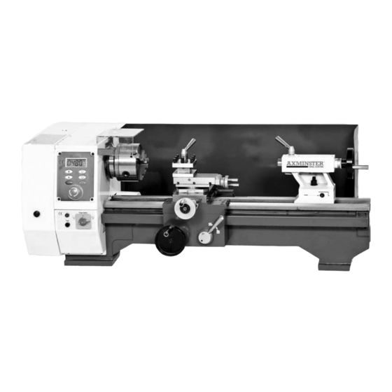
- Page 1 SIEG SC6 Variable Speed Lathe 951542 Mill Attachment for the SC6 Lathe. (Manual See Pages 31-50) Axminster Tool Centre, Unit 10 Weycroft Avenue, Axminster, Devon EX13 5PH www.axminster.co.uk...
- Page 3 A) 1 No. Tailstock Centre Gears B) 1 No. Headstock Dead Centre J) 1 No. 30 Teeth C) 3 No. External Jaws K) 1 No. 40 Teeth D) 1 No. ‘C’ Spanner L) 2 No. 42 Teeth E) 1 No. Spanner for Change Wheel M) 1 No.
- Page 4 IDENTIFICATION OF SC6 VARIABLE SPEED LATHE Code: 210172 1. Thread Pitch Gearing & Speed Charts 15. Compound Slide Handwheel 2. Speed Up Button 16. Tailstock Centre 3. Machine ID/Safety Label 17. Tailstock Clamp Bolt 4. Emergency Stop Switch 18. Tailstock Axis Alignment Indicator 5.
- Page 5 Release the Emergency Stop Button (4) by INITIAL START SC6 turning the knob head to right, the Digital Readout Speed Display (22) wlll come on. Press the start button (21), the spindle will be forward turning; the speed is 100r/min. Press the reverse button (25) to turn the spindle in the oppsite direction.
- Page 6 OPERATIONS Digital Readout FWD/REV Buttons Speed Display Variable Speed Controls Start Button Stop Button Emergency Stop Button Power Indicator Selector Switch Fuse...
- Page 15 Your C6B bench lathe is a precision tool. In order to maintain this precision and prolong its useful life, it is advised that you follow the recommended daily and periodic maintenance tables printed below. 1. Using an oil can with a narrow nozzle, oil all the oil points on the machine, incl. A) Saddle (4), B) tailstock (2), C) traverse slide (1), D) compound slide (2), E) leadscrew gearbox (2), and F) leadscrew end bearing (1).
- Page 16 Lubricant - Rocol Slideway lubricant spray (Part Number: 810141). Cutting Fluid - Rocol Multisol Cutting Fluid (Part Number: 810140). There are numerous accessories listed for the machine listed in the Axminster catalogue in section 2 . 1. Fixed Shaft Gear 2.
- Page 22 SC6 WIRE DIAGRAM...
- Page 31 SIEG SC6 Mill Attachment...
-
Page 32: Declaration Of Conformity
DECLARATION OF CONFORMITY The undersigned, Galen Chen authorised by Shanghai SIEG Machinery Co., Ltd. No.555 Caofeng Rd., South to No. 17 Bridge of Caoan Rd., Shanghai. P.R.China declares that this product: manufactured by Shanghai SIEG Machinery Co. is in compliance with the following standards or standardisation documents in accordance with Council Directives EN13128: 2001+A1: 2006 + A2: 2009/AC: 2010... -
Page 33: Specifications
Having unpacked your machine and its accessories, please check the contents against the equipment list "What’s in the box", if there are any discrepancies, please contact Axminster Tool Centre using the procedures laid down in the catalogue. Please dispose of the packaging responsibly, much of the material is bio-degradable. - Page 34 INITIAL ASSEMBLY - REMOVING THE SPLASH GUARD DISCONNECT THE LATHE FROM THE MAINS SUPPLY 1) Remove the four Phillip screws and pull out the electrical back plate to the rear of the lathe and lay the circuit board to one side. (See fig 1 & 2 ) (NOTE.
- Page 35 INITIAL ASSEMBLY - REMOVING THE SPLASH GUARD 3) Loosen the two bolts and washers which clamps the opposite end of the splash guard to the side of the lathe bed, below the tailstock. (See fig 5) 4) Remove the splash guard and place safely aside. Fig 5 INITIAL ASSEMBLY - MOUNTING THE MILL When mounting the Mill to the Lathe, we strongly advise you get...
- Page 36 INITIAL ASSEMBLY - FITTING THE MILL Step 3 TWO MAN ASSEMBLY Leg lock nut WARNING HEAVY Tip the lathe forward and have your assistant thread the support leg up into the angle support casting. Adjust the support leg until it makes contact with the surface of your bench or stand, tighten the lock nut to lock the leg in position.
- Page 37 INITIAL TESTING Please read the section entitled Identification and Parts description so that you may more easily identify the parts to which reference is made in the text. When the Mill is mounted to your satisfaction, proceed as follows:- a) Close the chuck jaws b) Check the millhead is ‘locked’...
-
Page 38: Parts Identification And Description
PARTS IDENTIFICATION AND DESCRIPTION Please take some time to identify the various parts of your machine so that you are familiar with the terminology we will use to enable you to set up and operate your Mill safely and correctly. Main tool post This is the column of the mill, it is an 65 x 50 bar with a dovetail slide machined on the front onto which the milling head is... - Page 39 MACHINE ILLUSTRATION OF THE MILL...
- Page 40 PARTS IDENTIFICATION AND DESCRIPTION Tri-Lever feed Three levered handle that is used to drive the quill (and hence the chuck or the tool) up and down. The boss of the handle is fitted to the end of a ‘splined’ gear shaft. This ‘splined’ gear is, in turn, engaged in the rack cut into the quill body.
- Page 41 MACHINE ILLUSTRATION OF THE MILL...
- Page 42 MACHINE ILLUSTRATION OF THE MILL To engage the fine feed control push the tri-lever assembly in until it meshes with the bevel gear. Pulling the tri-lever back will disen gage the fine feed control.
- Page 43 GENERAL OPERATING INSTRUCTIONS Warning. Do not operate the mill in any function unless the head clamping lever is tightened. TOOL CHANGING Note. The taper socket in the spindle mandrel does not have a ‘drive flat’ and all tooling, including the drill chuck is secured and driven by the taper lock and the draw bar. Make sure the power is switched off or better still remove the power from the machine.
- Page 44 MILL TABLE ASSEMBLY The Mill/Drill includes a milling table as an accessory. To install the milling table the compound slide must be removed from the cross slide from the lathe bed. Once installed, the milling table can move back and forth with the cross slide. Follow the instruction below to install table. Fig A 1) Using a 12mm spanner remove the two bolts that secure the compound slide to...
- Page 45 Give the motor a good ‘blow through’ to remove any dust, dirt etc, b) Check all the interlocks function correctly. Accessories There are numerous accessories for the machine listed in the Axminster catalogue. Some are illustrated at the rear of this manual. (See page 47)
- Page 46 MAINTENANCE OILING POINTS...
- Page 47 Part No: (100023) Part No: (100024) Micro Mill Clamping Kit Clamping kit Part No: (100033) Axminster Bull Nose Slot Drills Axminster HSS End Mills Axminster HSS Slot Drills Metric Screwed Shank Two Flute Bull Nose Slot Drills Metric Screwed Shank Three Flute End Mills.
- Page 48 PARTS BREAKDOWN FOR THE MILL...
- Page 49 PARTS BREAKDOWN FOR THE MILL...
- Page 50 PARTS LIST FOR THE MILL...