Table of Contents
Advertisement
Quick Links
o p e r a t o r ' s m a n u a l
Important Export Restrictions! Commodities, products,
technologies and services contained in this manual are
subject to one or more of the export control laws and
regulations of the U.S. Government and they fall under the
control jurisdiction of either the US Department of State
or the US BIS-Department of Commerce. It is unlawful
and strictly prohibited to export, or attempt to export or
otherwise transfer or sell any hardware or technical data or
furnish any service to any foreign person, whether abroad
or in the United States, for which a license or written
approval of the U.S. Government is required, without
first obtaining the required license or written approval
from the Department of the U.S. Government having
jurisdiction. Diversion contrary to U.S. law is prohibited.
ATN Mars 2
ATN Mars 4
ATN Mars 6
NIGHT VISION RIflEScOpES
MarS 2/ MarS 4/ MarS 6 operator'S ManUal (rev. 4, JUne 2011)
Advertisement
Table of Contents

Related Manuals for ATN Mars 2


Summary of Contents for ATN Mars 2
- Page 1 ATN Mars 4 ATN Mars 6 NIGHT VISION RIflEScOpES MarS 2/ MarS 4/ MarS 6 operator’S ManUal (rev. 4, JUne 2011) o p e r a t o r ’ s m a n u a l Important Export Restrictions! Commodities, products,...
- Page 2 Corp. atn Corp. assumes no responsibility or liability for any errors or inaccuracies that may appear in this book. © 2011 atn Corp. all right reserved.
- Page 3 STUDY cAREfUllY THIS MANUAl BEfORE TURNING ON AND OpERATING THIS pRODUcT. cAUTIONS The ATN Mars series night vision scopes are precision electro- optical instruments and require careful handling. please follow the below instructions of safe use: • Do not disassemble the scope.
- Page 4 EqUIpMENT lIMITATIONS to avoid injuries and equipment damage from using the atn Mars series, carefully read and consider the following equipment limita- tions. • The equipment requires some night light (moonlight, starlight, etc.) to operate. the level of equipment performance depends upon the level of light.
-
Page 5: Table Of Contents
1.2.1. Description 1.2.2. Mars Standard Components and optional equipment SEcTION II. OpERATING INSTRUcTIONS 2.1. Installation procedures 2.1.1. atn night vision riflescopes Mounting System 2.1.2. atn Double lever Quick release Mount (optional) 2.1.3. long rail adapter (optional) 2.2. Operating procedures 2.2.1. General 2.2.2. - Page 6 SEcTION III. OpERATIONAl DEfEcTS 3.1. Zeroing Operational Defects 3.1.1. Shading 3.1.2. edge Glow 3.1.3. Flashing, Flickering, or Intermittent operation 3.1.4. Cosmetic Blemishes SEcTION IV. MAINTENANcE INSTRUcTIONS 4.1. preventive Maintenance checks and Services (pMcS) 4.1.1. purpose of pMCS 4.1.2. pMCS procedures 4.2.
-
Page 7: Section I. Introduction
SEcTION I INTRODUcTION... -
Page 8: General
1.1.1. ScOpE this manual contains instructions for use in operating and main- taining the atn Mars series night vision riflescopes. throughout this manual, the atn Mars night vision riflescope will be referred to as the scope or the Mars. 1.1.2. REpORTS reports from the user on recommendations for improvements are encouraged. -
Page 9: Warranty
Customer’s sole and exclusive remedy. this warranty does not cover a product (a) used in other than its normal and customary man- ner;... - Page 10 Customer; ATN’s obligations under this Agreement extend solely to the Customer. ATN’s liability hereunder for damages, regardless of the form or action, shall not exceed the fees or other charges paid to ATN by the customer or customer’s dealer.
-
Page 11: Description And Data
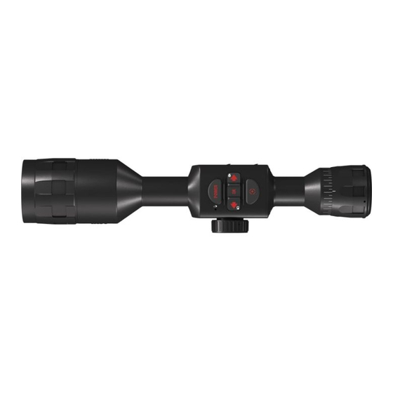
Mars series of night vision weapon sights is designed for professional purposes. the series includes scopes with 2.5X (atn Mars 2), 4X (atn Mars 4) and 6X (atn Mars 6) magnifica- tion. Similar to all atn scopes the atn Mars features only the purest... - Page 12 1-1. ATN MARS 2 NIGHT VISION wEApON SIGHT fIGURE 1-2. ATN MARS 4 NIGHT VISION wEApON SIGHT fIGURE 1-3. ATN MARS 6 NIGHT VISION wEApON SIGHT...
- Page 13 TABlE 1-1. SpEcIfIcATION MARS 2 MARS 4 MARS 6 Generation 2nd+, 3rd, 4th lens of system F 7 0 ; 1:1. 5 F 10 8 ; 1:1. 5 F 16 0 ; 1: 2 . 0 Magnification 2.5X 14 deg.
-
Page 14: Mars Standard Components And Optional Equipment
Mars standard components are shown in Figure 4-1 and pre- sented in table 1-2. fIGURE 1-4. MARS STANDARD cOMpONENTS TABlE 1-2. MARS STANDARD cOMpONENTS ITEM DEScRIpTION Front lens Cap atn Mars night vision riflescope Mounting System eye Cap Cr123a type battery remote Control IR Illuminator Kit operator’s Manual... - Page 15 1.5 mm Allen Key Ir450 Wrench optional items are shown in Figure 1-6 and listed in table 1-4. fIGURE 1-6. MARS OpTIONAl EqUIpMENT TABlE 1-4. MARS OpTIONAl EqUIpMENT ITEM DEScRIpTION ITEM cODE long rail adapter aCWSlraDpt ATN Double Lever QRM KIt aCWSMrSXQrM1...
- Page 16 ATN Double Lever QRM KIt is shown in Figure 1-7 and listed in table 1-5. fIGURE 1-7. ATN DOUBlE lEVER qRM KIT TABlE 1-5. ATN DOUBlE lEVER qRM KIT ITEM DEScRIpTION ATN Double Lever QRM KIt Screw Wrench 1.5 mm Allen Key...
-
Page 17: Section Ii. Operating Instructions
SEcTION II OpERATING INSTRUcTIONS... -
Page 18: Installation Procedures
2.1. INSTAllATION pROcEDURES 2.1.1. ATN NIGHT VISION RIflEScOpES MOUNTING SYSTEM the atn night vision riflescopes Mounting System allows to change the position of the riflescope flexibly on the weapon in relation to a shooter in combination with the fixed positions al- ready available on the weaver rail. -
Page 19: Atn Double Lever Quick Release Mount (Optional)
2.1.2. ATN DOUBlE lEVER qUIcK RElEASE MOUNT (OpTIONAl) atn Double lever Quick release Mount (QrM) is used for fast installation/removing the atn Mars series night vision rifle- scopes on MIl-StD-1913/picatinny rail. fIGURE 2-3. DOUBlE lEVER qUIcK RElEASE MOUNT... - Page 20 OpENED pOSITION fIGURE 2-4. DOUBlE lEVER qUIcK RElEASE MOUNT ADjUSTMENT 1. remove the standard atn Mounting System from the scope. Unscrew the two mounting screws, which attach the atn Mounting System to the body of the scope. 2. Mount the QrM onto the scope with two mounting screws.
-
Page 21: Long Rail Adapter (Optional)
2.1.3. lONG RAIl ADApTER (OpTIONAl) long rail adapter (lra) is a quick detachable, multiple eye relief mounting base that attaches to weaver type rail and flat-top recei- vers designed to give flexibility in positioning your Mars upon a firearm with a picatinny or Weaver rail. Instal the long rail adapter as follows: 1. -
Page 22: Operating Procedures
2.2. OpERATING pROcEDURES 2.2.1. GENERAl this section contains instructions for placing the Mars in opera- tion. the function of controls is explained. cAUTION The Mars is a precision electro-optical instrument and must be handled carefully at all times. 2.2.2. cONTROlS lIGHt SenSor retICle FoCUs ADjUsTMENT KNoB... -
Page 23: Battery Installation
TABlE 2-2. MARS cONTROlS AND INDIcATORS cONTROlS fUNcTION StB — the scope is in standby mode. operation Switch oFF — the scope is off. on — the scope is on. Diopter adjusts the grain in the image is sharp. adjustment ring Focus adjustment Focuses the input lens. -
Page 24: Operating Procedures
Mars operates with one Cr123a battery using the bat- tery adapter or one aa type battery without battery adapter. Install the battery as follows: Install the battery into its housing with the polarity order shown on the main body of the unit. the Cr123a battery used with adapter. -
Page 25: Automatic Brightness Control
c) If necessary remove the scope from the rail in reverse order of installing. d) Unscrew the battery cap and take out the battery. replace the battery cap. Do not store the Mars with the battery still in e) return the scope and all accessories to the case. 2.2.5. -
Page 26: Low Battery Indicator
2.2.8 lOw BATTERY INDIcATOR When red leD in the field of view starts blinking it is time to change your battery. 2.2.9. fOcUSING to focus the scope you need to adjust the diopter ring first. Simply turn the diopter clockwise until it stops. then concentrate on any object and slowly turn the diopter back counter clockwise until the grain in the image is sharp. -
Page 27: Ir450 Illuminator
Staying in the dark, switch on your night vision device. If the visibility is low, you may use atn Ir450 to improve the situation. Still, you should remember that the Ir illuminator is just a source of infrared light so the greater is the chosen range of observation, the lesser its brightness becomes. - Page 28 LED lit on the back side of IR450. By pushing the buttons “+” and “-” you may adjust the IR brightness. Ir BrIGHtneSS aDJUStMent poWer leD InDICator Ir elevatIon aDJUStMent BatterY HoUSInG Cap Ir FoCUSInG Ir WInDaGe FIXInG nUt aDJUStMent BatterY HoUSInG WrenCH ALLEN KEY...
-
Page 29: Reticle
Mars 2 equipped with chevron rangefinder reticle or crosshair reticle. Mars 4 and Mars 6 have the Mil-dot reticle. chevron rangefinder reticle Chevron rangefinder reticle was designed to assist you in deter- mining the range of your target. - Page 30 the size of vertical lines is correspond to 6 feet at 900 yards distance. the horizontal distance between the two lines is cor- respond to 20 Moa. the vertical size of chevron in the centre of reticle is correspond to 6 feet at 300 yards distance. crosshair reticle Crosshair reticle gives a clearly aiming point, even when hard- to-see game blends into the background.
-
Page 31: Windage And Elevation
By measuring the height or width of a known (or approximately known target size) in mil-radians using the reticles, the target dis- tance can be calculated as follows. r = range in meters, H = target size in meters, M = mil-radians of the image size: R = 1000 * H / M Military shooters are trained to know that the common male torso is... -
Page 32: Stowage Of Mars
(Mars 2), 1/4 inch at 100 yards (Mars 4) or 1/6 inch at 100 yards (Mars 6) . When reaching the maximum range of rotation do not use force. elevatIon DUSt CapS WInDaGe fIGURE 2-15. wINDAGE AND ElEVATION ADjUSTMENT KNOBS 2.2.14. -
Page 33: Section Iii. Operational Defects
SEcTION III OpERATIONAl DEfEcTS... -
Page 34: Zeroing Operational Defects
Mars. these include shading, edge glow, flashing, flickering, and intermittent operation. -
Page 35: Edge Glow
However, some types of blemishes can get worse over time and interfere with the usabil- ity of the device. If you believe a blemish is a cause for rejection, warranty or repair please atn or point of purchase for warranty/ repair procedures. - Page 36 If the bright spot remains, re- turn the atn Mars. Bright spots usually go away when the light is blocked out. Make sure any bright spot is not simply a bright area in the scene you are viewing.
- Page 37 c. Black Spots these are cosmetic blemishes in the image intensifiers or dirt or debris between the lenses. Black spots are acceptable as long as they do not interfere with viewing the image. no action is required if this condition is present unless the spots interfere with the us- ability of the device.
- Page 38 E. chicken wire an irregular pattern of dark thin lines in the field of view either throughout the image area or in parts of the image area (Figure 3-5). Under the worst-case condition, these lines will form hexag- onal or square-wave shaped lines. this is typically viewed in high light conditions.
-
Page 39: Section Iv. Maintenance Instructions
SEcTION IV MAINTENANcE INSTRUcTIONS... -
Page 40: Preventive Maintenance Checks And Services (Pmcs)
4.1. pREVENTIVE MAINTENANcE cHEcKS AND SERVIcES (pMcS) 4.1.1. pURpOSE Of pMcS pMCS is performed daily when in use to be sure that the scope is ready at all times. procedures listed in table 4-1 are a systematic inspection of the Mars that will enable you to discover defects that might cause the scope to fail on a mission. - Page 41 TABlE 4-1. pREVENTIVE MAINTENANcE cHEcKS AND SERVIcES SEq. ITEM TO NOT fUllY MISSION cHEcKING pROcEDURE cHEcK cApABlE If: Inspect for broken or miss- Switch missing. ing switch. Check for operation (with- Switch inoperative. operation o u t b at ter y) . tur n t h e Switch switch from oFF to on.
- Page 42 TABlE 4-1. pREVENTIVE MAINTENANcE cHEcKS AND SERVIcES SEq. ITEM TO NOT fUllY MISSION cHEcKING pROcEDURE cHEcK cApABlE If: oPERATIoNAL CHECKs cAUTION Operate the Mars with front lens cap on or under dark con- ditions. Inser t the batter y. turn the switch to on position.
-
Page 43: Troubleshooting
4.2. TROUBlESHOOTING 4.2.1. GENERAl this section contains information for locating and removal most of the Mars operating troubles which may occur. each malfunction of an individual component or assembly is followed by a list of tests or inspections that will help determine probable causes and corrective action to take. - Page 44 TABlE 4-2. TROUBlESHOOTING pROcEDURES pROBlEM pROBABlE cAUSE cORREcTIVE AcTION S c o pe af fe c ts Factory alignment bro- Send the scope to the ser- boresight after ken. vice center. inst allati o n or loose scope mounting tighten hard the fixing nuts during the firing.
-
Page 45: Maintenance Procedures
4.3. MAINTENANcE pROcEDURES 4.3.1. MARS MAINTENANcE the Mars maintenance consists of external inspection of its com- ponents for serviceability, cleaning and installation of the stan- dard and optional accessories. Maintenance instructions covered elsewhere in this manual (pMCS, troubleshooting, etc.) are not repeated in this section. -
Page 46: Appendix A. Estimation Of Ambient Illumination Level
AppENDIx A (Reference) ESTIMATION Of AMBIENT IllUMINATION lEVEl TABlE A-1. STANDARD NATURAl lIGHT cONDITIONS AND IllUMINATION VAlUES STANDARD NATURAl lIGHT IllUMINATION VAlUE, cONDITIONS Quarter moon 0.05 Full moon 0.30 late twilight sky 1.00 twilight sky 10.00 overcast sky in the daytime 500.00... -
Page 47: Appendix B. Spare Parts List
Spare parts list. the amount and assortment of the spare parts needed should be arranged with each contract individually. TABlE B-1. ATN MARS SpARE pARTS lIST pART NO. DEScRIpTION fIG. ITEM AT 146555.700... - Page 48 TABlE B-1. ATN MARS SpARE pARTS lIST pART NO. DEScRIpTION fIG. ITEM AT 146545.700 Accessories 1 (from the Kit) at 146542.710 IR 450 Kit at 146542.711 remote Control at 146545.712 operator's Manual at 541002.702 Shipping/Storage Case AT 146556.700 Accessories 2 (Optional) at 146556.751...
- Page 49 fIGURE B-1. NIGHT VISION ScOpE fIGURE B-2. AccESSORIES 1 (fROM THE KIT) fIGURE B-3. AccESSORIES 2 (OpTIONAl)
- Page 50 AppENDIx c TUBE MAINTENANcE/REplAcEMENT tube maintenance/replacement is to be performed by qualified technicians only. these procedures attempted by non-qualified personnel will void warranty. c-1. ScOpE DISASSEMBlY fIGURE c-1. ScOpE DISASSEMBlY 1. remove eyepiece (Subassembly 1). Use eyepiece Wrench St.t.01.000. 2. take out the set of insert rings the eyepiece was packed with for safer transportation.
- Page 51 5. loosen nut (8) of Subassembly (9) (reticle screw) and release reticle screw from Item (10) of Subassembly (11) (Figure C-2). 12±0.3 fIGURE c-2 6. Use Wrench Ct.00.03.000 to take out thread ring (12). 7. Draw tube Holder Subassembly (11) out of the scope body. c-2.
- Page 52 3. push the trimmed compensation ring, then tube fitted inside the IIt Container into the tube holder. Secure them with thread ring 15 (using Wrench St.00.03.000) and Screws (16) (to ar- rest the tube transverse offset). Double check Screws (16) are not overtightened! Use primer coat to lock the ring and the screws.
- Page 53 the thickness of the set of compensation rings is deduced from formula: x=D-E-f. loosen the screw, unsolder the tube wires off the plate, and take the tube holder out of the scope body. trim fit the set of compen- sation rings for the needed thickness x. b) assemble the scope with the set of compensation rings 2.5mm thick.
- Page 54 vertically strict and the “M” dimension is provided for (Figure C-2). Secure Subassembly (9) with nut (8). lock the nut with primer coat. 9. Install the eyepiece. Secure it with primer coat. fIGURE c-5 10. eliminate the parallax between the crosshair plane and the target plane and allow for less than 1º...
-
Page 55: For Technical Information
TEcHNIcAl INfORMATION ATN cORp. 1341 San Mateo avenue South San Francisco, Ca 94080 (800) 910-2862 (650) 989-5100 tel. (650) 875-0129 fax www.atncorp.com info@atncorp.com InFo-1... - Page 56 800-910-2862, 650-989-5100; fax: 650-875-0129 European Office the following countries can use our toll free number: 00 800 9102-8620 austria, France, Germany, Holland, Italy, Spain, Sweden, Switzerland For other countries, please use 38 048-7770214 or 38 048-7770345 www.atncorp.com ©2011 atn Corporation...