
Related Manuals for Trane TTA240F Series


Summary of Contents for Trane TTA240F Series
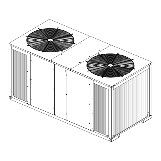
- Page 1 TTA-SVN03A-EN Installation Operation Maintenance Split System Cooling Condensers 20-Ton Model (60 Hz): Model (50 Hz): TTA240F***A TTA200FD**A June 2006...
-
Page 2: Preface And Cautions And Warnings
Preface and Cautions and Warnings Literature Change History Warnings and Cautions TTA-SVN03A-EN (June 2006) Notice that warnings and cautions Release of 20T, R410A product. appear at appropriate intervals throughout this manual. Warnings are Note: One copy of this document provided to alert installing contractors ships inside the control panel to potential hazards that could result of each unit and is customer... -
Page 3: Table Of Contents
Table of Contents Preface and Cautions and Warnings......... Model Number Description............Electrical Data................Installation..................System Prestart Procedure............System Test Mode (ReliaTel)............Troubleshooting (ReliaTel)............Maintenance................Warranty..................TTA-SVN03A-EN... -
Page 4: Model Number Description
Model Number Description Model Number Description TTA 090 A 3 00 B A All products are identified by a multiple-character model number that DIGITS 9, 10: FACTORY INSTALLED DIGITS 1-3: PRODUCT TYPE precisely identifies a particular type of OPTIONS unit. An explanation of the TTA = Split System Cooling 00 = Packed Stock alphanumeric identification code is... -
Page 5: Dimensional Data
Dimensional Data Figure 1. TTA200F, TTA240F, Dimensional Data, Connection Location, Clearances, Corner Weights APPROXIMATE CORNER WEIGHT (MASS) TOTAL UNIT TOTAL SHIPPING MODEL NO. WEIGHT WEIGHT TTA240F---A 292 lbs 181 lbs 222 lbs 140 lbs 835 lbs 920 lbs TTA200FD--A 132 kg 82 kg 101 kg 64 kg... -
Page 6: Electrical Data
Electrical Data Table 1. TTA Unit Electrical Data Basic Unit Characteristics Compressor Motor Outdoor Fan Motor Allowable Minimum Maximum Model Electrical Voltage Circuit Fuse Amps Amps Number Characteristics Range Ampacity Size Qty. Qty. TTA240F3 208-230/60/3 187-254 89.4 35.3 239.0 14.4 TTA240F4 460/60/3 414-506... -
Page 7: Installation
Installation Installation procedures should be power supply must be compatible Lifting Recommendations performed in the sequence that they with electrical characteristics specified Before preparing the unit for lifting, appear in this manual. Do not destroy on component nameplates. Replace estimate the approximate center of or remove the manual from the unit. - Page 8 Installation Clearances Figure 2. Roof Mounted Unit possible noise or vibration problems. Any ground level location must Provide enough space around the unit comply with required clearances to allow unrestricted access to all given in Figure 1. service points. Refer to Figure 1 for unit dimensions and minimum Refrigerant Piping required service and free air...
- Page 9 Installation Refrigerant Piping Procedures CAUTION CAUTION (Outdoor Units) Install a regulating valve between the Do not remove the seal caps from nitrogen source and the gauge refrigerant connections, or open the Each TTA unit ships with a holding manifold (Figure 3). Unregulated service valves until prepared to braze charge of dry nitrogen.
- Page 10 Installation System Evacuation Charge by weight through the gauge Gaseous Charging port on the liquid line. Once the After completion of leak check, This procedure is accomplished with charge enters the system, backseat evacuate the system. the unit operating. Electrical (open) the liquid line service valve connections must be complete.
- Page 11 24 volts storing components provided by Unit Power Supply Add 5 wires, 24 volts Trane or others, refer to the Note: 1) Wiring shown with dashed The installer must provide line voltage appropriate manufacturer’s literature lines is to be furnished...
- Page 12 Installation Figure 6. Typical Field Wiring - ReliaTel Control TTA240F/TWE240E Field Wiring: Note: 1) Wiring shown with dashed 3 power wires, line voltage lines is to be furnished 3 power wires, line voltage for 3 and installed by the phase; 2 wires for single phase customer.
- Page 13 Installation Figure 7. Night Setback Panel Field Wiring Figure 8. Zone Sensor Field Wiring Figure 9. Thermostat Field Wiring TTA-SVN03A-EN...
- Page 14 Installation Figure 10. TTA240F-TWE240E Refrigerant Circuit TTA-SVN03A-EN...
-
Page 15: System Prestart Procedure
System Pre-Start Procedure Safety Controls Internal Overload Protector (IOL) Installation Checklist Note: All of these controls may not This device is a thermal actuated snap Complete this checklist once the unit be installed on your unit, disc, imbedded in the compressor. It is installed to verify that all check electrical schematic. - Page 16 System Start Procedure Electromechanical Controls Unit Start-Up Cooling Mode Once the unit is properly installed and With the disconnect switch in the ON pre-start procedures are complete, position, current is supplied to the start the unit by turning the System compressor sump heater(s) and Switch on the indoor thermostat to control transformer.
-
Page 17: System Start Procedure Reliatel Controls
System Start Procedure ReliaTel™ Controls Unit Start-Up ReliaTel Control Cooling Mode ReliaTel Control Evaporator Fan Operation Once the unit is properly installed and When the system switch is set to the pre-start procedures are complete, COOL position and the zone When the fan selection switch is set to start the unit by turning the System temperature rises above the cooling... -
Page 18: System Test Mode (Reliatel)
System Test Modes ReliaTel™ Controls Test Modes There are three methods in which the 3. Auto Test Mode - This method is “Service Test” can be cycled at LTB- not recommended for start-up due to Upon power initialization, the RTRM Test 1(T1) and LTB-Test 2 (T2). -
Page 19: Troubleshooting (Reliatel)
Troubleshooting ReliaTel™ Controls Trouble Shooting ReliaTel Note: If a System failure is indicated, Method 1 proceed to Step 4. If no Controls If the Zone Sensor Module (ZSM) is failures are indicated, proceed equipped with a remote panel with The RTRM has the ability to provide to Step 5. -
Page 20: Troubleshooting
Troubleshooting ReliaTel™ Controls Resetting Cooling and Heating Cooling Failure Heat Failure Lockouts Cooling and heating set point Measure the voltage between (slide pot) on the zone sensor has Cooling Failures and Heating Lockouts terminals J6-7 & J6-6. failed. Refer to the “Zone Sensor are reset in an identical manner. - Page 21 Troubleshooting ReliaTel™ Controls Temperature Tests Programmable & Digital Zone Test 4 - LED Indicator Test, (SYS Sensor Test ON, HEAT, & COOL) Note: These procedures are not for programmable or digital Testing serial communication Method 1 models and are conducted voltage with the Zone Sensor Module Testing the LED using a meter with...
-
Page 22: Maintenance
• Wash clothes separately from Trane or others, refer to the is in good condition to prevent other clothing: rinse washer appropriate manufacturer’s literature water leakage. - Page 23 Maintenance Log Maintenance Log* Date Ambient Evaporator Compressor Superheat Subcooling Temp. Entering Air Circuit #1 Circuit #1 Suction Discharge Bulb Bulb Pressure Pressure Perform each inspection once per month (during cooling season) while unit is operating TTA-SVN03A-EN...
-
Page 24: Warranty
Warranty Central Air Conditioner TTA (Parts Only) THE WARRANTY AND LIABILITY SET FORTH HEREIN ARE IN LIEU OF ALL This warranty is extended by OTHER WARRANTIES AND American Standard to the original LIABILITIES, WHETHER IN CONTRACT purchaser and to any succeeding OR IN NEGLIGENCE, EXPRESS OR owner of the real property to which IMPLIED, IN LAW OR IN FACT,... - Page 25 Warranty Related Accessories Commercial Equipment Rated 20 THE WARRANTY AND LIABILITY SET FORTH HEREIN ARE IN LIEU OF ALL Tons and Larger and Related OTHER WARRANTIES AND Accessories (Parts Only) LIABILITIES, WHETHER IN CONTRACT Products Covered — This warranty OR IN NEGLIGENCE, EXPRESS OR is extended by American Standard IMPLIED, IN LAW OR IN FACT, Inc., and applies only to commercial...
- Page 26 TTA-SVN03A-EN...
- Page 27 TTA-SVN03A-EN...
- Page 28 Literature Order Number TTA-SVN03A-EN File Number SV-UN-TTA-SVN03A-EN-06/06 Supersedes Stocking Location Ship with/WebbMason The manufacturer has a policy of continuous product and data improvement and reserves the right to change design and specifications without notice.