Table of Contents
Advertisement
Installation, Operation,
and Maintenance
Blower Coil Air Handler
Air Terminal Devices
400 to 3000 cfm
Models BCHC and BCVC
"AO" and later design sequence
September 2002
BCXC-SVX01A-EN
Advertisement
Table of Contents

Related Manuals for Trane BCHC


Summary of Contents for Trane BCHC
-
Page 1: And Maintenance
Installation, Operation, and Maintenance Blower Coil Air Handler Air Terminal Devices 400 to 3000 cfm Models BCHC and BCVC “AO” and later design sequence BCXC-SVX01A-EN September 2002... -
Page 2: Installation
Use this manual for commercial blower concluded that ozone in our upper situation which, if not avoided, may coil models BCHC and BCVC. This is the atmosphere is being reduced due to the result in minor or moderate injury. It first version of this manual. -
Page 3: Table Of Contents
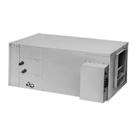
Contents Cross reference to related publications/information for blower coil units with Tracer ZN controls: • Installation, Operation, and Programming Guide for Tracer ZN010 and ZN510 Unit Controllers, CNT-IOP-1 • Installation, Operation, and Programming Guide for Tracer ZN520 Unit Controller, CNT-SVX04A-EN •... - Page 4 3 hp motor with same side of unit position drive selections from 400 to 1800 rpm Control box Figure I-GI-1. Blower coil air handler unit components. Model BCHC, horizontal unit, is shown. BCXC-SVX01A-EN...
- Page 5 BC H C 012 1 C A0 A 1 G A 2 B 0 000 0 0 2 C 3 B A 2 2 B 2 0 5 R A 0 1 1 0 Digits 1 thru 4 — Unit Model B = 2-row heating Digit 16 — Motor Horsepower BCHC = horizontal blower coil C = 4-row heating 0 = none 4 = 1 hp...
- Page 6 General Installation Information Digit 22 — Electric Heat Controls Digit 29 — Coil #1 Piping Package Digit 35 — Factory Mounted Control Options 0 = none 0 = none A = 24 volt magnetic contactors 0 = none 1 = basic piping package B = 24 volt mercury contactors A = fan status 2 = deluxe piping package...
-
Page 7: Pre-Installation Considerations
IAQ problems, store the unit indoors. If ! ! Inspect individual cartons before installation location. indoor storage is not possible, the Trane accepting. Check for rattles, bent carton Company makes the following provisions Service Access... - Page 8 Pre-Installation Installation Considerations Rigging and Handling Unit Location Before preparing the unit for lifting, WARNING Recommendations estimate the approximate center of gravity for lifting safety. Because of When selecting and preparing the unit Improper Unit Lift! placement of internal components, the installation location, consider the Test lift the unit approximately 24 unit weight may be unevenly distributed,...
-
Page 9: Table Of Contents
Dimensions Installation and Weights Horizontal Blower Coil *NOTE: ON UNITS WITHOUT A BOTTOM FILTER ACCESS SECTION top view 11.25 12.79 front view right side view Horizontal Blower Coil Unit Dimensions and Weights, in-lbs. Unit unit Size G (RH) G (LH) weight 14.00 24.00... -
Page 10: Table Of Contents
Dimensions Installation and Weights Vertical Blower Coil *NOTE: ON UNITS WITHOUT A vertical counter swirl TOP FILTER ACCESS SECTION top view configuration vertical preswirl configuration 11.25 front view 30.00 Vertical Blower Coil Unit Dimensions and Weights, in-lbs. Unit unit Size G (RH) G (LH) weight... - Page 11 Dimensions Installation and Weights Angle Filter & Mixing Box combination angle filter & mixing box mixing box angle filter box Angle Filter & Mixing Box Dimensions and Weights, in-lbs. NOTES: 1. ALL DIMENSIONS ARE IN INCHES. Unit 2. MIXING BOX SHIPS ASSEMBLED FOR FIELD INSTALlatION. Size weight 3.
- Page 12 Dimensions Installation and Weights Bottom or Top Access Filter 7.17 FILTER AIR FLOW FILTER AIR FLOW FILTER ACCESS PANEL top view right side view RIGHT SIDE NOTES: 1. DIMENSIONS ARE IN INCHES. 2. ROTATE 180° FOR TOP ACCESS. 3. SECTION SHIPS ATTACHED TO THE UNIT. Bottom or Top Access Filter Box Dimensions and Weights, in-lbs.
- Page 13 Dimensions Installation and Weights Electric Heat top view front view right side view Electric Heat Dimensions and Weights, in-lbs. Unit Size weight 14.06 17.88 8.13 6.79 10.50 7.75 0.03 10.0 14.06 19.88 10.13 8.79 10.50 7.75 0.03 10.8 18.06 21.25 7.63 6.29 13.50...
- Page 14 Dimensions Installation and Weights Steam Coil ACCESS PANEL 0.97 NOTES: 1. FILTER ACCESS & ACCESS PANEL LOCATED ON BOTH SIDES. 2. WEIGHT INCLUDES CABINET WITH AVERAGE FILTER, BUT DOES NOT INCLUDE COIL WEIGHT. SEE GENERAL DATA SECTION FOR COIL WEIGHTS. 0.97 21.00 Steam Coil Box Dimensions and Weights, in-lbs.
- Page 15 Dimensions Installation and Weights Piping Packages Basic Piping Deluxe Piping Two-Way, ” & 1” Basic Piping Package Two-Way, ” & 1” Deluxe Piping Package Two-Way, 1 ” Basic Piping Package Two-Way 1 ” Deluxe Piping Package Three-Way, ” & 1” Basic Piping Package Piping Package Dimensions, in.
-
Page 16: Mechanical Requirements
If a fire hazard exists, Trane recommends using Plug or trap the auxiliary connection to Flexweave 1000, type FW30 or equiva- prevent air from being drawn in and lent canvas. - Page 17 Mechanical Installation Requirements Water Coil Connections Piping Packages Water coils have sweat connections. Piping packages ship separate for field Reference coil connection dimensions in installation and have sweat type the Dimensions and Weights section. connections. Interconnecting piping is Proper installation and piping is field provided.
- Page 18 Refrigerant Coil Piping CAUTION indicating sight glass, filter drier, manual ball shutoff valves, access port, and The DX cooling coil in a BCHC/BCVC unit possibly a solenoid valve. Position these Disassemble the thermal expansion is equipped with a single distributor...
-
Page 19: Field-Installing Evaporator Piping
Mechanical Installation Requirements Field-Installing Evaporator that matches the suction-header Piping connection. 4 For the vertical riser, use the tube See Figure I-MR-3 and refer to the diameter recommended by the instructions below to field-install condensing unit manufacturer. Assure evaporator piping. the top of the riser is higher than the 1 Pitch the liquid line slightly—1 in./10 ft evaporator coil. -
Page 20: Electrical Requirements
Electrical Installation Requirements Unit Wiring Diagrams CAUTION All input/output circuits (except isolated relay contacts and optically isolated Correct phase critical! Specific unit wiring diagrams are inputs) assume a grounded source, provided on the inside of the control Correct phase sequence is critical. If either a ground wire at the supply panel door. - Page 21 Electrical Installation Requirements Minimum Circuit Ampacity (MCA) and Table I-ER-2. Available Electric Heat Kw (min.-max) Maximum Fuse Size (MFS) Calculations Unit Size for Units with Electric Heat Voltage Use these formulas to calculate the MCA and MFS. 115/60/1 1- 3 208/60/1 1- 8 Heater amps = (heater kW x 1000)/...
- Page 22 Electrical Installation Requirements Table I-ER-3. Motor Electrical Data Voltage voltage range rated hp lbs. 115/60/1 104-126 1750 22.8 30.4 12.0 58.4 12.8 58.4 two-speed 115/60/1 104-126 1750/1160 8.9/6.1 42.0 11.5/8.1 58.2 208-230/60/1 187-253 1750 11.4 15.2 29.2 29.2 277/60/1 249-305 1750 15.5 12.1...
-
Page 23: Installation Procedure
Installation Procedure Installing the Unit Follow the procedures below to install the blower coil unit. Horizontal Units, Model BCHC Install horizontal units suspended from the ceiling with ” threaded rods that are field provided. There are two knockouts in each corner of the unit for installation of the threaded rods. - Page 24 Installation Installation Procedure Vertical Units, Model BCVC Install vertical units on the floor. Units are provided with legs that are field-installed to help accomodate a U-trap on the drain connection, if necessary. A field- fabricated inlet plenum is not required. The unit is shipped in two pieces, and can be arranged in either a pre-swirl or counter-swirl inlet configuration.
-
Page 25: Mixing Box Option
Installation Installation Procedure Heating Coil Option Mixing Box Installation Procedure 1. Support the mixing box independent of the unit in the horizontal position. Note: The hydronic heating coil option is 2. Install the mixing box as a sleeve factory installed in either the reheat or around the duct collar of the filter preheat position. - Page 26 Installation Installation Procedure Installing Wall Mounted • Radiant heat from the sun, fireplaces, installation holes. Ensure the base is Controls appliances, etc. level. • Airflow from adjacent zones or other b. Set the base aside and make the Wall mounted zone sensors ship taped to units.
-
Page 27: Pre-Startup Requirements
Rover service tool) to the telephone (b) Class 2 Type CL2P style RJ11 connection on the zone sensor • Trane Part No. 400-20-28 or equivalent, module. Attach the other end of the cable available through Trane BAS Buying to a computer running Trane Rover Group Accessories catalog. - Page 28 Pre-Startup Installation Requirements Pre-Startup Checklist ! Extend discharge duct upward without Unit Location ! Remove crating from the unit. Do not change in size or direction for at least Complete this checklist after installing the remove the shipping skid until the unit is one and one half fan diameters.
-
Page 29: Operation
Control Options Tracer ZN510 and ZN520 ZN510 can be used as either a stand- Blower coil air handlers are available alone or as part of a Trane Integrated without controls or with one of four Comfort System (ICS). different control options: •... - Page 30 General Operation Information Table O-GI-1. Tracer Controller Input/Output Summary Tracer Controller ZN010 ZN510 ZN520 Binary Outputs 2-speed fan 2-position hydronic valve 2-position mixing box damper 1-stage electric heat modulating mixed air damper modulating hydronic valve 2-stage electric heat reheat (hydronic) generic Binary Inputs condensate overflow detection...
- Page 31 General Operation Information Table O-GI-3. End Device Option Availability Control Tracer Tracer Tracer Device Interface ZN010 ZN510 ZN520 condensate float switch low limit filter status filter run-time diagnostic fan status positive proof fan status switch 2-position control valves modulating control valves 2-position mixing box actuator modulating mixing box actuator 1-stage electric heat...
-
Page 32: Sequence Of Operation
Sequence of Operation Operation Tracer ZN Controller Sequence Unoccupied Mode A communicated request will control the of Operation When the controller is in the unoccupied controller’s occupancy. Typically, this mode, the controller attempts to request comes from the BAS time-of-day Power-Up Sequence maintain space temperature at the scheduling to the controller. -
Page 33: Heating Operation
Based on the controller’s pied standby fan operation to be defined disconnected. Refer to Trane publication, occupancy mode, the active heating as abnormal. Refer to the Troubleshoot- CNT-SVX04A-EN Installation Operation... -
Page 34: Fan Mode Operation
Sequence of Operation Operation Between 0 and 100% capacity, the in auto, the fan speed can switch depend- heating output is controlled according to ing on the error. The fan speed increases modulating valve logic (ZN520 only) or as the space temperature rises above the cycled with 2-position valves. - Page 35 Sequence of Operation Operation Table O-SO-2. Tracer ZN520 Fan Configura- when the unit is off due to a diagnostic or single or two-speed fan to work coopera- tion when the unit is in the off mode due to the tively to meet precise capacity require- Auto local zone sensor module, a communi- ments, while minimizing fan speed...
-
Page 36: Fan Operation During Occupied Heating
Sequence of Operation Operation Fan Operation During Occupied Heating Table O-SO-4. Fan Mode Operation, Tracer ZN010 and ZN510 Modes Heating Mode Cooling Mode The ZN520 fan output(s) normally run Fan Mode Occupied Unoccupied Occupied Unoccupied continuously during the occupied and occupied standby modes, but cycle off/high (3) off/high (3) - Page 37 Sequence of Operation Operation Two and Four-Pipe Table O-SO-8. Unit Mode as Related to Water Temperature Changeover Operation Unit Type EWT Sensor Required? Coil Water Temperature • Can cool if: space temp - EWT 5 deg F 2-pipe changeover Tracer ZN controllers offer accurate and •...
- Page 38 Rover space temperature at the current service tool. For more information on setpoint. setup, refer to the Trane publication A typical scenario involves high humidity EMTX-IOP-2. and high temperature load of the space.
-
Page 39: Analog Inputs
Sequence of Operation Operation Binary Inputs Analog Inputs Note: See the “Diagnostics” section for more information. Tracer ZN controllers have the following See Table O-SO-11 on page 40 for a binary inputs, factory-configured for the complete description of analog inputs. following functions: BIP2: Condensate Overflow Detection •... - Page 40 Sequence of Operation Operation Table O-SO-11. Analog Inputs Analog Input Terminal Function Range ZN010 ZN510 ZN520 Zone TB3-1 Space temperature input 5° to 122°F (-15° to 50°C) Ground TB3-2 Analog ground TB3-3 Setpoint input 40° to 115°F (4.4° to 46.1°C) TB3-4 Fan switch input 4821 to 4919 W (Off)
- Page 41 Sequence of Operation Operation Zone Sensor When a building automation system or Fan Switch other controller communicates a setpoint The zone sensor fan switch provides the The Tracer ZN controller accepts the to the controller, the controller ignores the controller with an occupied (and occupied following zone sensor module inputs: hardwired setpoint input and uses the standby) fan request signal (Off, Low,...
- Page 42 Sequence of Operation Operation Figure O-SO-14. Resistance temperature curve for the zone sensor, entering water temperature sensor, and discharge air sensor. BCXC-SVX01A-EN...
-
Page 43: Maintenance
Adjust sheaves and tighten the sheave because they may cause belt Hazardous Voltage! set screws to the correct torques recom- deterioration and slippage. Trane does mended in Table M-MP-1. not recommend belt dressing. Before servicing unit disconnect all electrical power including remote... - Page 44 Maintenance Maintenance Procedures Table M-MP-2. BCHC/BCVC Fan, Filter, & Mixing Box General Data Unit Size nominal cfm 1200 1800 2400 3000 airflow minimum cfm 1125 1500 1875 maximum cfm 1000 1600 2400 3000 4000 Fan Data fan wheel dia., in.
- Page 45 Maintenance Maintenance Procedures Table M-MP-4. BCHC/BCVC Coil General Data Unit size Nominal cfm 1200 1800 2400 3000 Note 5 Hydronic & DX Coil area, ft 0.83 1.04 1.74 2.78 3.89 4.86 6.25 width, in. Note 1 12.5 12.5 17.5 17.5 22.5...
- Page 46 Browning Fan RPM Range Unit Motor Motor Speed (Hz) Drive Size Motor Watts Sheave Trane Sheave Trane Belt BR Trane 1750 (60 hz) 1450 (50 hz) Letter 186–1119 to 1 1VL40 X 5/8 X10090082090 AL74 X X10070170080 X10200254140 619–878 513–727...
- Page 47 Maintenance Maintenance Procedures Steam, Hot Water, and Cooling Coil Keep coils clean to maintain maximum performance. For operation at its highest Cleaning Procedure 1.Don the appropriate personal efficiency, clean the coil often during periods of high demand or when dirty protective equipment (PPE).
- Page 48 Maintenance Maintenance Procedures Periodic Maintenance Semi-Annual Maintenance Checklists 1. Verify the fan motor is properly lubricated. Follow lubrication Monthly Checklist recommendations on the motor tag or The following check list provides the nameplate. Contact the motor recommended maintenance schedule to manufacturer for more information.
-
Page 49: Troubleshooting
Maintenance Troubleshooting LED Activity Table M-T-1. Red Service LED Activity LED Activity Description Red Service LED Off continuously after Normal operation The red LED normally indicates if the unit power is applied to the controller. controller is operating properly or not. Reference Table M-T-1. - Page 50 Troubleshooting Maintenance The green LED is turned off when the Table M-T-4. Tracer ZN010 and ZN510 Test Sequence for 1–Heat /1–Cool Configurations Test button is pressed. To begin the Steps Cool Output (1) Heat Output Damper manual output test mode, press and hold J1-1, J1-3 the Test button (turning off the green 1.
-
Page 51: Diagnostics
When you press Trane’s Service Tool, Rover™ There are six ways to reset unit Rover™, Trane’s service tool, can reset the Test button, the controller exercises diagnostics: all outputs in a predefined sequence. The diagnostics present in the controller. - Page 52 Maintenance Diagnostics Table M-D-1. Tracer ZN010 and ZN510 Controller Diagnostics Diagnostic Latching Valves Elect. Heat Damper Auxiliary enabled no action no action no action temp. failure Condensate closed closed overflow detection Entering enabled enabled enabled enabled water temp. Fan mode enabled enabled enabled...
- Page 53 Maintenance Common Diagnostics Table M-D-3. Fan Outputs Do Not Energize Probable Cause Explanation Random start After power-up, the controller always observes a random start that varies observed between 0 and 30 seconds. The controller remains off until the random start time expires.
- Page 54 Diagnostics Maintenance Table M-D-4. Valves Stay Closed Probable Cause Explanation Normal operation The controller opens and closes the valves to meet the unit capacity require- ments. Requested mode: off It is possible to communicate the operating mode (such as off, heat, and cool) to the controller.
- Page 55 Diagnostics Maintenance Table M-D-6. Electric Heat Not Operating Probable Cause Explanation Normal operation The controller cycles electric heat on and off to meet the unit capacity requirements. Requested mode: off It is possible to communicate the operating mode (such as off, heat, cool) to the controller.
- Page 56 Refer to the Manual Output Test section. Fan mode off When a local fan mode switch (provided on the Trane zone sensor) determines the fan operation, the off position controls the unit off and valves to close.
- Page 57 Maintenance Diagnostics Table M-D-10. DX or electric outputs do not energize Probable Cause Explanation Unit wiring The wiring between the controller outputs and the end devices must be present and correct for normal operation. Unit configuration The controller must be properly configured based on the actual installed end devices and application.
-
Page 58: Typical Wiring Diagrams
Typical Wiring Maintenance Diagram Two-Pipe BCXB with Tracer ZN510 • 208 volt/3 phase • 2- position damper • single stage electric heat • 2-positon valve •condensate overflow •wall-mounted zone sensor BCXC-SVX01A-EN... - Page 59 Typical Wiring Maintenance Diagram Four-Pipe BCXB with Tracer ZN510 • 208 volt/3 phase • 2-position valves • 2-position damper • condensate overflow • low limit protection • wall-mounted zone sensor BCXC-SVX01A-EN...
- Page 60 Typical Wiring Maintenance Diagram Four-Pipe BCXB with Tracer ZN510 • 115 volt/1 phase • 2-position valves • 2-position damper • 2-speed motor • condensate overflow BCXC-SVX01A-EN...
- Page 61 Typical Wiring Maintenance Diagram Two-Pipe BCXB with Tracer ZN520 • 460 volt/3 phase • fan status switch • 2-position valve • condensate overflow • economizer damper • wall-mounted zone sensor • 2-stage electric heat BCXC-SVX01A-EN...
- Page 62 Typical Wiring Maintenance Diagram Four-Pipe BCXB with Tracer ZN520 • 460 volt/3 phase • 2-position valves • condensate overflow • fan status switch BCXC-SVX01A-EN...
- Page 63 Typical Wiring Maintenance Diagram Four-Pipe BCXB with Tracer ZN520 • 460 volt/3 phase • 2-position valves • condensate overflow • fan status switch BCXC-SVX01A-EN...
- Page 64 Typical Wiring Maintenance Diagram Four-Pipe BCXB with Tracer ZN520 • 460 volt/3 phase • fan status switch • economizer damper • wall-mounted zone sensor • condensate overflow BCXC-SVX01A-EN...
- Page 65 Typical Wiring Maintenance Diagram Four-Pipe BCXB with Tracer ZN520 • 460 volt/3 phase • fan status switch • 3-wire floating point valves • wall-mounted zone sensor • economizer damper • condensate overflow BCXC-SVX01A-EN...
- Page 66 Typical Wiring Maintenance Diagram Four-Pipe BCXB with Control interface • 208 volt/3 phase • 3-wire floating point valves • 2-position damper • low limit protection • condensate overflow BCXC-SVX01A-EN...
- Page 67 Typical Wiring Maintenance Diagram Four-Pipe BCXB with Control interface • 115 volt/1 phase • 2-position damper • 2-speed motor • condensate overflow • low limit protection BCXC-SVX01A-EN...
- Page 68 NOT INSTALL WIRES IN CONDUIT THAT CONTAINS WIRES 24VAC OR HIGH VOLTAGE POWER WIRES. OR HIGH VOLTAGE POWER WIRES. COMMUNICATION WIRE MUST BE TRANE PART NO. COMMUNICATION WIRE MUST BE TRANE PART NO. 400-20-28, OR WINDY CITY OR CONNECT AIR 400-20-28, OR WINDY CITY OR CONNECT AIR "LEVEL 4"...
- Page 69 GROUND GROUND OR HIGH VOLTAGE POWER WIRES. OR HIGH VOLTAGE POWER WIRES. COMMUNICATION WIRE MUST BE TRANE PART NO. COMMUNICATION WIRE MUST BE TRANE PART NO. 400-20-28, OR WINDY CITY OR CONNECT AIR 400-20-28, OR WINDY CITY OR CONNECT AIR "LEVEL 4"...
-
Page 70: Table Of Contents
Index fan off delay 35 fan operation during occupied heating about this manual 2 modes 36 acronyms 2 fan operation in heating and cooling air filters 43 modes 36 analog inputs 40 fan sequence of operation 35 annual maintenance 48 fan speed switch 34 fan start on high speed 35 fan switch 41... - Page 71 Index unit location recommendations 8 unit mode as related to water tempera- power-up sequence 32 ture 37 pre-installation checklist 8 unit mounting 28 pre-startup checklist 28 unit nameplate 8 pre-startup procedures 26 unit panels 28 unit piping 28 unit start-up 27 receiving 28 unit startup procedures 28 receiving and handling 7...
- Page 72 For more information contact your local office or e-mail us at comfort@trane.com Trane has a policy of continuous product improvement and reserves the right to change design and specifications An American Standard Company without notice. Only qualified technicians should install and service equipment.