
Related Manuals for Trane Tracer CH.530 RLC-SVU01B-E4


Summary of Contents for Trane Tracer CH.530 RLC-SVU01B-E4
- Page 1 Owner Manual Tracer CH.530™ Chiller Control System “HO” Design Sequence EasyView and DynaView Interfaces RLC-SVU01B-E4...
-
Page 2: Foreword
Foreword Reception These Installation, Operation, and On arrival, inspect the unit before Maintenance instructions are given signing the delivery note. Specify as a guide to good practice in the any damage on the delivery note, installation, start-up, operation, and and send a registered letter of periodic maintenance by the user of protest to the last carrier of the Tracer CH.530 chiller control... -
Page 3: Table Of Contents
Contents Foreword ........Warranty . -
Page 4: Commonly Used Abbreviations
RAS = Reset Action Set Point RLA = Rated Load Amperes RCWS = Reset Chilled-Water Set Point RRS = Reset Reference Set Point Tracer ™ = Type of Trane Building Automation System UCLS = Unit Current-Limit Set Point UCM = Unit Control Module (Microprocessor-based) RLC-SVU01B-E4... -
Page 5: Ch.530 Communications Overview
The CH.530 uses the IPC3 protocol based on RS485 signal technology Communications Overview and communicating at 19.2 Kbaud, to The Trane CH.530 control system that allow three rounds of data per runs the chiller consists of several second on a 64-device network. A... -
Page 6: Easyview Interface
Water) Setpoint. It will NOT display diagnostic readout should be noted the Evaporator Entering Water and is for the use of Trane service. Temperature or the Ice Termination Setpoint even when they are active during the “Ice Building” mode of operation. -
Page 7: Inputs
BAS Auto/Stop Low-Ambient Start Inhibit BAS here and elsewhere in this manual refers to the Trane Tracer™ Equipment Controller. The interlock LED will stop flashing when the condition that prevents machine operation is corrected. No reset is required. -
Page 8: Diagnostic Reset
EasyView Interface Diagnostic Reset If the machine is in a diagnostic condition (LED is flashing), a transition from Stop to Auto will reset the diagnostic. If the machine is in the Stop State (Auto LED off), depressing the AUTO key will reset all diagnostics. -
Page 9: Dynaview Interface
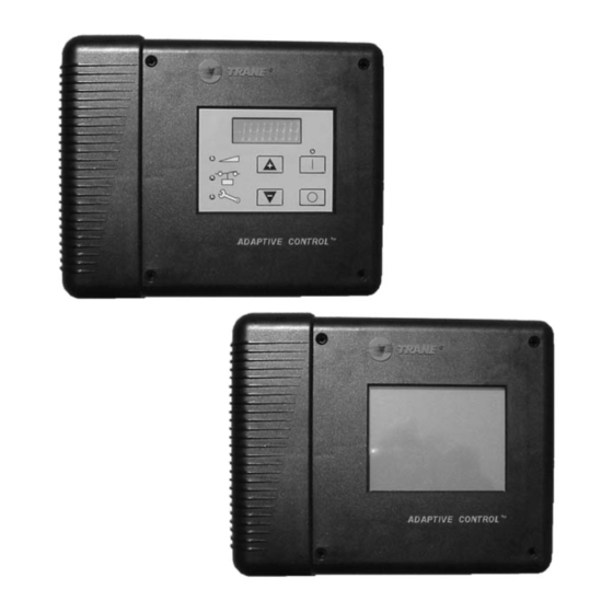
DynaView Interface DynaView Interface Figure 2 – DynaView Display The DynaView and EasyView share the same enclosure design: weatherproof and durable plastic for use as a stand-alone device on the outside of the unit or mounted nearby. The display on DynaView is a 1/4 VGA display with a resistive touch screen and an LED backlight. -
Page 10: Controls Interface
Controls Interface Basic Screen Format The basic screen format appears as: Legend 1. File folder tabs 2. Page-by-page scroll up 3. Line-by-line scroll up/down 4. Page-by-page scroll down 5. Navigator 6. Reduce contrast/viewing angle 7. Radio buttons 8. Increase contrast/viewing angle Auto Stop Alarms... - Page 11 Controls Interface Front Panel Lockout Feature DISPLAY AND TOUCH SCREEN ARE LOCKED NOTE: The DynaView display and ENTER PASSWORD TO UNLOCK Touch Screen Lock screen is shown below. This screen is used if the Display and touch screen and lock feature is enabled.
-
Page 12: Modes Screen
Controls Interface Modes Screen Compressor Chiller Modes Chiller Mode: Running Circuit 1 Mode: Running - Limit Cpsr 1A Mode: Running Cpsr 1B Mode: Running Circuit 2 Mode: Run Inhibit Cpsr 2A Mode: Stopped Cpsr 2B Mode: Stopped Auto Stop The Mode Screen is only found on software revisions 18 and later. - Page 13 Controls Interface Table 1 - Chiller Modes Description Chiller Modes The chiller is not running and cannot run without intervention. Further Stopped (1) information is provided by the sub-mode: Chiller is stopped by DynaView (or EasyView). Stop button command Local Stop (2) cannot be remotely overridden.
- Page 14 Controls Interface Ice Building to Normal Transition (2) The chiller is inhibited from running for a brief period of time if it is commanded from active ice building mode into normal cooling mode via the ice building hardwired input or Tracer. This allows time for the external system load to "switchover"...
- Page 15 Controls Interface Table 2 - Circuit modes Circuit Modes Description Stopped (1) The given circuit is not running and cannot run without intervention. Further information is provided by the sub-mode: Front Panel Lockout (2) The circuit is manually locked out by the circuit lockout setting - the nonvolatile lockout setting is accessible through either the DynaView or TechView.
- Page 16 Controls Interface Capacity Limited by Low Liquid Level (2) The circuit is experiencing low refrigerant liquid levels and the EXV is at or near full open. The compressors on the circuit will be unloaded to prevent tripping. Shutting Down (1) The given circuit is still running but shutdown is imminent.
- Page 17 Controls Interface Table 3- Compressor Modes Compressor Modes Description Stopped (1) The given compressor is not running and cannot run without intervention. Further information is provided by the sub-mode:- Diagnostic Shutdown - Manual Reset (2) The compressor has been shutdown on a latching diagnostic. Service Tool Lockout (2) The compressor has been shutdown due to a command from the TechView Service Tool to be "locked out"...
- Page 18 Controls Interface Capacity Limited by Phase Unbalance (2) The compressor is running and its capacity is being limited by excessive phase current unbalance. Shutting Down (1) The given compressor is still running but shutdown is imminent. The compressor is going through either a run-unload mode or is the active compressor in the operational pumpdown cycle for its circuit.
- Page 19 Controls Interface Chiller Screen The chiller screen is a summary of the chiller activity. Chiller Compressor Modes Evap Leaving Water Temperature: Evap Entering Water Temperature: 12 C Active Chilled Water Setpoint: Active Current Water Setpoint: 100% Outdoor Air Temperature: 22 C Software Version: 18.0 AAutouto...
- Page 20 Controls Interface The last screen has a single arrow to Compressor Screen scroll upward one line at a time. The compressor screen displays When in the last position, the single information for the compressors in down arrow disappears. the format shown. The top line of Each compressor has its own screen radio buttons allows you to select depending on which radio key is...
- Page 21 Controls Interface Refrigerant Screen The refrigerant screen displays those aspects of the chiller related to the refrigerant circuits. Compressor Rfgt. Chiller Ckt 1 Ckt 2 Cond Rfgt Pressure: 1275 1275 kPa Sat Cond Rfgt Temp: 51.7 51.7 Evap Rfgt Pressure: Sat Evap Rfgt Temp: Evap Approach Temp: Rfgt Liquid Level:...
- Page 22 Controls Interface Setpoint Screen Screen 2 displays the current value of the chosen setpoint in the upper The setpoint screen is a two-part ½ of the display. screen. Screen 1 lists all setpoints It is displayed in a changeable available to change along with their format consistent with its type.
- Page 23 Controls Interface Table 7 - Setpoint screen Description Resolution or Text Units Auto Local or Remote Remote/Local Text Front Panel Chilled Water Setpoint F / C Front Panel Current Limit Setpoint % RLA Differential to Start Temperature Differential to Stop Temperature Condenser Limit Setpoint Enable/Disable...
- Page 24 Controls Interface Table 8 - Setpoint Options/Conditions Displayed Option Condition(s) Explanation Ice Building Enable/Disable If feature is installed, operation can be initiated or stopped Cprsr Pumpdown (1) Avail Pumpdown is allowed: only with unit in Stop or when circuit is locked out Not Avail Pumpdown is not allowed because...
- Page 25 Controls Interface Diagnostic Screen Rfgt Set Point Diagnostic Reset Diags [01] 10: 59 AM Nov 26, 2001: Evaporator Water Flow Overdue: [02] 10: 56 AM Nov 26, 2001: Low Chilled Water Temp: Unit Off: [03] 10: 55 AM Nov 26, 2001: Low Evaporator Temp: Unit Off: Auto Alarms...
-
Page 26: Techview Interface
Controls Interface contact your local Trane service Power-Up DynaView agency for assistance with any On Power-Up, DynaView will service requirements. progress through 3 screens: TechView software is available via First Screen, Version # of the Boot, Trane.com. full version # displayed. -
Page 27: Software Download
Controls Interface Software Download - To do this, click on the latest version of the main processor. Instructions for First Time TechView - Select "Save this program to disk" Users while downloading the files (do not 1. Create a folder called "CH.530" on select your C:\ drive. -
Page 28: Diagnostics
Diagnostics The following Diagnostic Table Persistence: Defines whether or not contains all diagnostics possible the diagnostic and its effects are to arranged alphabetically by the name be manually reset (Latched), or can assigned to each diagnostic. Not all be either manually or automatically diagnostics are available unless reset (Nonlatched). - Page 29 Diagnostics Diagnostic Name and Severity Persistence Criteria Reset Code Source Level BAS Failed to Special NonLatch The BAS was setup as Remote Establish "installed" and the BAS did not Communication communicate with the MP within 15 minutes after power- up. Refer to Section on Setpoint Arbitration to determine how setpoints and operating modes may be...
- Page 30 Diagnostics Diagnostic Name and Severity Persistence Criteria Reset Code Source Level Comm Loss: Cond Rfgt Immediate Latch Same as Comm Loss: Chilled Remote Pressure, Circuit #1 Water Flow Switch Comm Loss: Cond Rfgt Immediate Latch Same as Comm Loss: Chilled Remote Pressure, Circuit #2 Water Flow Switch...
- Page 31 Diagnostics Diagnostic Name and Severity Persistence Criteria Reset Code Source Level Comm Loss: Normal Latch Same as Comm Loss: Chilled Remote Evaporator Rfgt Drain Water Flow Switch Valve - Ckt 2 Comm Loss: Immediate Latch Same as Comm Loss: Chilled Remote Evaporator Rfgt Liquid Water Flow Switch...
- Page 32 Diagnostics Diagnostic Name and Severity Persistence Criteria Reset Code Source Level Comm Loss: External Special Latch Continual loss of Remote Circuit Lockout, Mode communication between the Circuit #1 MP and the Functional ID has occurred for a 30 second period. MP will nonvolatilely hold the lockout state (enabled or disabled) that was in effect at the time of comm loss.
- Page 33 Diagnostics Diagnostic Name and Severity Persistence Criteria Reset Code Source Level Comm Loss: Fan Normal Latch Same as Comm Loss: Chilled Remote Control Circuit #2, Water Flow Switch Stage #4 Comm Loss: Fan Special Latch Continual loss of Remote Inverter Fault, Circuit Mode communication between the #1 or Circuit #1,...
- Page 34 Diagnostics Diagnostic Name and Severity Persistence Criteria Reset Code Source Level Comm Loss: Female Normal Latch Same as Comm Loss: Chilled Remote Step Load Water Flow Switch Compressor 2A Comm Loss: Female Normal Latch Same as Comm Loss: Chilled Remote Step Load Water Flow Switch Compressor 2B...
- Page 35 Diagnostics Diagnostic Name and Severity Persistence Criteria Reset Code Source Level Comm Loss: Immediate Latch Same as Comm Loss: Chilled Remote Intermediate Oil Water Flow Switch Pressure, Cprsr 2A Comm Loss: Immediate Latch Same as Comm Loss: Chilled Remote Intermediate Oil Water Flow Switch Pressure, Cprsr 2B Comm Loss: Local...
- Page 36 Diagnostics Diagnostic Name and Severity Persistence Criteria Reset Code Source Level Comm Loss: Oil Normal Latch Same as Comm Loss: Chilled Remote Temperature, Circuit Water Flow Switch #2 or Cprsr 2A Comm Loss: Oil Normal Latch Same as Comm Loss: Chilled Remote Temperature, Water Flow Switch...
- Page 37 Diagnostics Diagnostic Name and Severity Persistence Criteria Reset Code Source Level Comm Loss: Starter Info Latch Same as Comm Loss: Chilled Local Panel High Water Flow Switch Temperature Limit - Panel 2, Cprsr 2B Comm Loss: Status/ Info Latch Same as Comm Loss: Chilled Remote Annunciation Relays Water Flow Switch...
- Page 38 Diagnostics Diagnostic Name and Severity Persistence Criteria Reset Code Source Level Condenser Fan Special Latch The MP has received a fault Remote Variable Speed Drive Mode signal from the respective Fault - Circuit 1 condenser fan Variable Speed (Drive 1) Inverter Drive, and unsuccessfully attempted (5 times within 1 minute of...
- Page 39 Diagnostics Diagnostic Name and Severity Persistence Criteria Reset Code Source Level Evaporator Leaving Normal Latch Bad Sensor or LLID Remote Water Temperature Sensor Evaporator Liquid Immediate Latch Bad Sensor or LLID Remote Level Sensor - Circuit 1 Evaporator Liquid Immediate Latch Bad Sensor or LLID Remote...
- Page 40 Diagnostics Diagnostic Name and Severity Persistence Criteria Reset Code Source Level Evaporator Water Immediate NonLatch a. The chilled water flow switch Remote Flow Lost input was open for more than 6-10 contiguous seconds. b. This diagnostic does not de- energize the evaporator pump output c.
- Page 41 Diagnostics Diagnostic Name and Severity Persistence Criteria Reset Code Source Level External Chilled Water Info NonLatch a. Function Not "Enabled": no Remote diagnostics. Setpoint b. "Enabled": Out-Of-Range Low or Hi or bad LLID, set diagnostic, default CWS to next level of priority (e.g. Front Panel SetPoint).
- Page 42 Diagnostics Diagnostic Name and Severity Persistence Criteria Reset Code Source Level High Evaporator Immediate NonLatch The evaporator refrigerant Remote pressure of either circuit has Refrigerant Pressure risen above 13.3 bar. The evaporator water pump relay will be de-energized to stop the pump regardless of why the pump is running.
- Page 43 Diagnostics Diagnostic Name and Severity Persistence Criteria Reset Code Source Level High Pressure Cutout Immediate Latch A high pressure cutout was Local - Compressor 1A detected on Compressor 1A; trip at 22 ± 0.35 bar. Note: Other diagnostics that may occur as an expected consequence of the HPC trip will be suppressed from...
- Page 44 Diagnostics Diagnostic Name and Severity Persistence Criteria Reset Code Source Level Low Chilled Water Immediate NonLatch The chilled water temperature Remote Temp: Unit On and Special fell below the cutout setpoint Mode for 16.7°C seconds while the compressor was running. Automatic reset occurs when the temperature rises 2 °F (1.1°C) above the cutout setting...
- Page 45 Diagnostics Diagnostic Name and Severity Persistence Criteria Reset Code Source Level Low Evaporator Immediate Latch a. The inferred Saturated Remote Refrigerant Evaporator Refrigerant Temperature - Temperature (calculated from Circuit 1 suction pressure transducer(s)) dropped below the Low Refrigerant Temperature Cutout Setpoint for 66.7°C-sec (4.4°C- sec max rate) while the circuit was running after the ignore...
- Page 46 Diagnostics Diagnostic Name and Severity Persistence Criteria Reset Code Source Level Low Evaporator Temp Special NonLatch Same as Low Evaporator Temp Remote - Ckt 1: Unit Off Mode - Ckt 1: Unit Off Local Low Oil Flow - Immediate Latch The intermediate oil pressure Compressor 1A transducer for this compressor...
- Page 47 Diagnostics Diagnostic Name and Severity Persistence Criteria Reset Code Source Level Low Suction Immediate Latch Same as Low Suction Local Refrigerant Pressure - Refrigerant Pressure - Circuit 1 Circuit 2B Motor Current Immediate Latch Compressor current exceeded Local Overload - overload time vs.
- Page 48 Diagnostics Diagnostic Name and Severity Persistence Criteria Reset Code Source Level MP: Reset Has Info NonLatch The main processor has Remote Occurred successfully come out of a reset and built its application. A reset may have been due to a power up, installing new software or configuration.
- Page 49 Diagnostics Diagnostic Name and Severity Persistence Criteria Reset Code Source Level Over Voltage Immediate NonLatch a. Line voltage above + 10% of Remote nominal. [Must hold = + 10 % of nominal. Must trip = + 15 % of nominal. Reset differential = min.
- Page 50 Diagnostics Diagnostic Name and Severity Persistence Criteria Reset Code Source Level Phase Reversal - Immediate Latch Same as Phase Reversal - Local Compressor 1B Compressor 1A Phase Reversal - Immediate Latch Same as Phase Reversal - Local Compressor 2A Compressor 1A Phase Reversal - Immediate Latch...
- Page 51 Diagnostics Diagnostic Name and Severity Persistence Criteria Reset Code Source Level Power Loss - Immediate NonLatch Same as Power Loss - Remote Compressor 2B Compressor 1A Pumpdown Info NonLatch The pumpdown cycle for this Remote Terminated - Circuit 1 circuit was terminated abnormally due to excessive time or due to a specific set of diagnostic criteria - but without...
- Page 52 Diagnostics Diagnostic Name and Severity Persistence Criteria Reset Code Source Level Starter 2A Comm Immediate Latch Starter has had a loss of Local Loss: MP communication with the MP for a 15 second period. Starter 2A Dry Run Immediate Latch While in the Starter Dry Run Local Test...
- Page 53 Diagnostics Diagnostic Name and Severity Persistence Criteria Reset Code Source Level Starter Contactor Special NonLatch Same as Starter Contactor Remote Interrupt Failure - Mode Interrupt Failure - Compressor Compressor 2B Starter Did Not Immediate Latch The Starter Module did not Local Transition - receive a transition complete...
- Page 54 Diagnostics Diagnostic Name and Severity Persistence Criteria Reset Code Source Level Starter Fault Type I - Immediate Latch This is a specific starter test Local Compressor 1A where 1M(1K1) is closed first and a check is made to ensure that there are no currents detected by the CT's.
- Page 55 Diagnostics Diagnostic Name and Severity Persistence Criteria Reset Code Source Level Starter Fault Type III - Immediate Latch As part of the normal start Local Compressor 1A sequence to apply power to the compressor, the Shorting Contactor (1K3) and then the Main Contactor (1K1) were energized.
- Page 56 Diagnostics Diagnostic Name and Severity Persistence Criteria Reset Code Source Level Starter Module Immediate Latch Same as Starter Module Local Memory Error Type 2 - Memory Error Type 1 - Starter 2A Starter 2A Starter Module Immediate Latch Same as Starter Module Local Memory Error Type 2 - Memory Error Type 1 -...
- Page 57 Diagnostics Diagnostic Name and Severity Persistence Criteria Reset Code Source Level Suction Refrigerant Immediate Latch Same as Suction Refrigerant Remote Pressure Transducer - Pressure Transducer - Circuit 1, Circuit 1, Compressor 1A Compressor 2b Transition Complete Immediate Latch The Transition Complete input Local Input Opened - was found to be opened with...
- Page 58 Diagnostics Diagnostic Name and Severity Persistence Criteria Reset Code Source Level Under Voltage Normal NonLatch a. Line voltage below - 10% of Remote nominal or the Under/Overvoltage transformer is not connected. [Must hold = - 10% of nominal. Must trip = - 15 % of nominal.
-
Page 59: Maintenance
Maintenance Contract and Training Maintenance Contract Training It is strongly recommended that you The equipment described in this sign a maintenance contract with manual is the result of many years of your local Service Agency. This research and continuous contract provides regular development. - Page 60 Stocking Location Europe Trane has a policy of continuous product and product data improvement and reserves the right to change design and specifications without notice. Only qualified technicians should perform the installation and servicing of equipment referred to in this publication.