Table of Contents
Advertisement
Advertisement
Table of Contents

Related Manuals for Trane UCM-CLD

Summary of Contents for Trane UCM-CLD
- Page 1 Owner Manual UCM-CLD Chiller Control System RLC-SVU02F-E4...
- Page 2 We would remind (or the site representative) must start-up. you that failure to respect these notify Trane Epinal Operations - installation and maintenance Claims team and send a copy of the Warnings and cautions instructions may result in immediate delivery note.
-
Page 3: Table Of Contents
Contents General Information Principles of operation of the UCM-CLD module General Information Operator’s Interface Operational Features Diagnostics Diagnostics Default Description Controller for hydraulic module/ free cooling / heat recovery / RTWB heat pump applications Hydraulic module control Control logic Module and outputs/inputs... -
Page 4: General Information
Communication Buffer) interferences (optional factory-mounted module, compulsory when using a Remote CLD) Interface between the control of the unit and a Building Management TCI IV, COM 3 (Tracer Communication Interface 4, COM 3) System using Trane COMM 3 serial link RLC-SVU02F-E4... -
Page 5: Operator's Interface
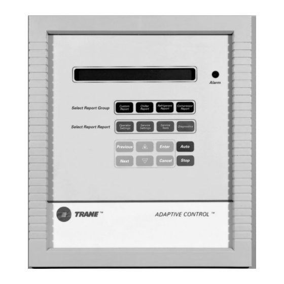
Service Settings Menu* Cancel key Service Test Menu* Auto key Diagnostics Menu Stop key * Levels 2 and 3 of the Service Settings Menu and the Service Test Menu are protected by a password and are reserved for Trane Service Engineers. RLC-SVU02F-E4... - Page 6 Principles of Operation of the Module UCM-CLD Control Key Functions [Auto key] Pressing this key allows the unit to be in Auto mode if it was [+] key If the information displayed previously placed in Stop mode is read-only, pressing this key will with the [Stop] key.
- Page 7 Principles of Operation of the Module UCM-CLD Parameters and setpoints within each menu Menu Parameters/setpoints Range Minimum/Maximum Chiller Report Menu Active Chilled Water Setpoint Evaporator Entering/ Leaving Chilled Water Temperature Condenser Entering / Leaving Chilled Water Temperature Active Ice-Storing Setpoint...
- Page 8 Principles of Operation of the Module UCM-CLD Service Settings Menu** LEVEL ONE-Information adjusted by customer Unit Line Voltage Over/Undervoltage Protection Restart Inhibit Time 30/120 sec Balanced Compressor Starts and Hours Display Language and Units Programmable Relay Set-up 1/12 External Circuit Lockout...
-
Page 9: Operational Features
Principles of Operation of the Module UCM-CLD Operational features Electronic expansion valve Current overload protection (EXV) test The UCM continually monitors Entering evaporator water This test can be performed only when compressor current to provide unit temperature the “Stop“ key has been pressed. It... - Page 10 Principles of Operation of the Module UCM-CLD Chilled-Water Reset (CWR) If the leaving-water temperature If the leaving-water temperature cutout is set upward, the Clear drops below the cutout setpoint As an option, the UCM will reset the Language Display will maintain the...
- Page 11 Principles of Operation of the Module UCM-CLD Low refrigerant temperature cutout If the leaving-water temperature If the saturated-evaporator cutout is set upward, the Clear refrigerant temperature for a circuit Both circuits are protected from a Language Display will maintain the...
- Page 12 Principles of Operation of the Module UCM-CLD Balanced compressor starts If phase-unbalanced protection Oil failure protection and hours (service setting menu) is enabled The logic of the UCM uses a and the average three-phase current This feature is enabled/disabled in...
- Page 13 Current limit Setpoint (CLS) Heat Recovery not able to provide chilled water for When either external CWS or UCM-CLD will not display leaving a process. The leaving chilled-water external CLS is used on the optional and entering water temperature temperature is not controlled. The module A9, DIP switch SW1 above 70.1°C, whereas on Total Heat...
- Page 14 • Setpoint decreases load the defined in the A70 Module. chiller • Setpoint increases unload the chiller Note that the UCM still operates as a chilled-water controller. On the UCM-CLD, the parameter “External Chilled Water setpoint” has to be enabled. RLC-SVU02F-E4...
- Page 15 Principles of Operation of the Module UCM-CLD Local/ External unit control mode Refer to Table 4 for the setting rule. From the Settings menu, the end - AI: External heating setpoint input user can select the Control mode. (configurable) - Control Mode: No This input will be powered in 0-1V or 4..20mA.
-
Page 16: Diagnostics
Diagnostics If there are no diagnostic messages, When a circuit shutdown - manual If more than one diagnostic is the selected menu item will be reset (CMR) or a machine shutdown present, only the highest priority displayed continuously. If the - manual reset (MMR) occurs, the active diagnostic will be explained diagnostics key is pressed and there... -
Page 17: Default Description
Diagnostics Default description Displayed Code Type Description Fault 87 Check External Chilled Water Setpt : - Value out of range Fault 89 Check External Current Limit Setpt : - Value out of range Fault 8A Chilled Water Flow (Ent Wtr Temp) : 1) Entering water temperature <... - Page 18 Diagnostics Default description Displayed Code Type Description Fault 180 Starter Transition - Cprsr A : 1) Transition proof signal not received 2) Proof input shunted Fault 181 Starter Transition - Cprsr B : 1) Transition proof signal not received 2) Proof input shunted Fault 182 Starter Transition - Cprsr C : 1) Transition proof signal not received...
- Page 19 Diagnostics Default description Displayed Code Type Description Fault 1AA EXV Elec Drtive Ckt - Rfgt Ckt 2 : 1) EXV wiring 2) Defective UCM 3) Defective EXV 4) Defective EXV relay - NOVRAM problem, unit is placed on default Fault 1Ad setting operating Memory Error Type I : Fault 1AE...
- Page 20 Diagnostics Default description Displayed Code Type Description Fault 1dE High Oil Temp - Cprsr B : - Oil temperature > 77°C Fault 1dF High Oil Temp - Cprsr C : - Oil temperature > 77°C Fault 1E0 High Oil Temp - Cprsr D : - Oil temperature >...
- Page 21 Diagnostics Communication Failures Displayed Code Description Fault 410 Loss of Local Display Panel Comm Fault 412 Chiller Mod to Option Mod Comm Failure Fault 413 Chiller Mod to EXV Mod Comm Failure Fault 414 Chiller Mod to Cprsr A Mod Comm Failure Fault 415 Chiller Mod to Cprsr B Mod Comm Failure Fault 416...
-
Page 22: Controller For Hydraulic Module/ Free Cooling / Heat Recovery / Rtwb Heat Pump Applications
Controller for hydraulic module/ free cooling / heat recovery / RTWB heat pump applications The aim of this section is to list available screens on the additional controller used to control Free Cooling /Heat Recovery application (version 1.0) and hydraulic modules. The built-in control terminal features: •... -
Page 23: Hydraulic Module Control
Reaction in case of failure doesn't demand pump activation. activation: • Failure on entering water Electric Heater ON/OFF When UCM-CLD does not require temperature sensor (EWT): pump activation and that ambient If the ambient air temperature is A failure on this sensor (value out... -
Page 24: Module And Outputs/Inputs
Heaters Electric Heaters Output J9 : N03(ac) / C1 Common Relays Outputs J10 : C4 FS_Out Flow Switch Output to the UCM-CLD J10 : N04(ac) / C4 Yes_Alarm Customer Information Output J11 : N05(ac) / C5 Common Relays Outputs J11: C5... -
Page 25: Hydraulic Module Option
"Pump 1 Running" Pump 1 is running "Pump 2 Running" Pump 2 is running "No Pump Request" No pump request sent by the UCM-CLD "Pump 1 OVD" Manual Override on pump 1 "Pump 2 OVD" Manual Override on pump 2 "System OFF"... -
Page 26: Data Display Menu
Hydraulic module control Data display menu The following mask will be accessed using the Up and Down keys Analog Inputs Return Wat T Outside Air T 1 = Customer return water temperature 2 = Ambient air temperature Digital Inputs Pump 1 Status: Normal Pump 2 Status: Normal... - Page 27 Hydraulic module control Settings Menu Access to each field within a mask using the Enter key. Change the field value using the Up and Down keys and confirmation by Enter . 1 = Access via password, 0000 to 9999 User Settings 1 = Pumps Rotation ( , Yes) Clock Menu...
-
Page 28: Alarms Messages - Hydraulic Module Application
Hydraulic module control Alarms Messages - Hydraulic module application History Events Alarm Screen Reset Type Comments Description Record See Application No Alarm No Alarm none status on Main display Faulty sensor, out of Alarm Faulty EWT No control on Auto range -38..+70°C EWT Sensor Sensor... -
Page 29: Free Cooling Application
Free Cooling Application Free Cooling Application Permanent display Access to this mask using the Esc key from any mask. The program will return automatically into it after 5 min. 1 = Application name and version number 2 = Current date and time 3 = Leaving water temperature 4 = Unit status: "Chiller Low Ambient"... - Page 30 Free Cooling Application Data display menu The following mask will be accessed using the Up and Down keys Analog Inputs 1 = Entering water temperature 2 = Leaving water temperature 3 = Ambient air temperature 4 = Active chilled water setpoint Setpoint Source 1 = Setpoint Source (Front Panel, External, Air Reset, Return Water Reset) 2 = Active chilled water setpoint...
- Page 31 Free Cooling Application Digital Inputs 1 = System (Off, On); NNSB (Off, On) 2 = UCM Pump (Not Req., Required) 3 = Flow Switch (OK, Not OK) 4 = Free Cooling (Disable, Enable) Digital Outputs 1 = Fans 1, 2 and 3 (Off, On) 2 = Fan Speed (Low, High) 3 = FC status (Off, On) 4 = UCM enabled (Off, On)
- Page 32 Free Cooling Application 3 Way Valve IO Speed Relay 1 = 3WV Input Position (Value and Input Analog Voltage) 2 = 3WV Output Position (Value and Output Analog Voltage) Chilled Water Setpoint IO 1 = External Chilled Water Setpoint (Value and Input Analog Voltage) 2 = Adjusted Water Setpoint Output (Value and Output Analog Voltage) Settings Menu Access to each field within a mask using the Enter key.
- Page 33 Free Cooling Application Chilled Water Reset CWR 1 = Reset Type (None, External, Based on OAT, Based on Ret Wat) "None" No reset has been requested "External" Reset comes from external source "Based on OAT" Reset is based on outdoor air temperature "Based on Ret Wat"...
- Page 34 Free Cooling Application Alarm Messages - Free Cooling Application History Events Reset Alarm Screen Unit status Description Record Type Free Cooling ON See unit status on No Alarm No Alarm Chiller ON Main display Faulty sensor, Faulty LWT Free Cooling OFF Alarm LWT Sensor Auto out of range...
-
Page 35: Heat Recovery Application
Heat Recovery Application Permanent display Access to this mask using the Esc key from any mask. The program will return automatically into it after 5min. HR Application V1.0 00/00/00 00:00 Hot Wat Temp: 00.0°C Cool&HR Mode Running 1 = Application name and version number 2 = Current date and time 3 = Hot water temperature 4 = Unit status:... - Page 36 Heat Recovery Application Access to Sub-menus Access to this mask using the Prg key. The sub-menu will be selected using the Up and Down keys and selected using the Enter button. 1 = Data display menu 2 = Settings menu 3 = Clock menu 4 = Unit configuration menu Data display menu...
- Page 37 Heat Recovery Application Digital Inputs Circuit 1: Running Circuit 2: Running HR Status: Enabled NNSB: 1 = Circuit 1 (Stopped, Running) 2 = Circuit 2 (Stopped, Running) 3 = Heat Recovery Status (Disabled, Enabled) 4 = Night Noise Set Back (Off, On) Digital Outputs FAN1: FAN2:...
- Page 38 Heat Recovery Application Settings Menu Access to each field within a mask using the Enter key. Change the field value using the Up and Down keys and confirmation by Enter. 1 = Access via password, 0000 to 9999 User Settings Hot Water SP: 50°C PRG Relay:...
- Page 39 Heat Recovery Application Alarms Messages - Heat Recovery Application History Events Alarm Screen Reset Type Unit status Description Record Heat See unit status on No Alarm No Alarm Recovery ON Main display Chiller ON Heat Alarm HWT Faulty HWT Faulty sensor, out of range Auto Recovery OFF Sensor...
-
Page 40: Rtwb Heat Pump Application
RTWB Heat Pump Application Permanent display Access to this mask using the "Esc" key from any mask. The program will return automatically into it after 5 min. 1 = Application name and version number 2 = Current date and time 3 = Condenser Leaving Water Temperature 4 = Unit status: none... - Page 41 RTWB Heat Pump Application Binary Outputs 1 = Active Mode (Heating, Cooling) 2 = Unit Status (Stopped, Running) 3 = CDS Pump Status (Stopped, Running) 4 = Sensor Alarm (Normal, Alarm) Active Setpoints 1 = Active Mode (Heating, Cooling) 2 = Heating Setpoint (displayed if Heating Mode) 3 = Cooling Setpoint (displayed if Cooling Mode) Note: "...
- Page 42 RTWB Heat Pump Application Settings Menu Access to each field within a mask using the " Enter " key. Change the field value using the Up and Down keys and confirmation by " Enter ". 1 = (0000 to 9999) User Settings 1 1 = Front Panel Heat Setpoint (25.0°C..60.0°C: 35.0°C) 2 = Front Panel Cool Setpoint (-12.0°C..18.0°C: 6.0°C)
- Page 43 RTWB Heat Pump Application Clock Menu 1 = Access via password, 0000 to 9999 Clock Settings 1 = Weekday (Mon, Tue, Wed, Thu, Fri, Sat or Sun) 2 = Time setting 3 = Date setting (dd/mm/yy) Alarms Messages - RTWB Heat pump application Alarm History Reset...
- Page 44 Supersedes RLC-SVU02E-E4_0508 Trane has a policy of continuous product and product data improvement and reserves the right to change design and specifications without notice. Only qualified technicians should perform the installation and servicing of equipment referred to in this publication.