Table of Contents
Advertisement
Operating Guide
This guide describes how to use the Agilent 53150A, 53151A, and 53152A
Microwave Frequency Counters. The information in this guide applies to
instruments having the number prefix listed below, unless accompanied
by a "Manual Updating Changes" package indicating otherwise.
SERIAL PREFIX NUMBER:
Agilent 53150A/151A/152A
Microwave Frequency Counter
3735A, US3925, and US4050 (53150A)
3736A, US3926, and US4051 (53151A)
3737A, US3927, and US4052 (53152A)
Advertisement
Table of Contents

Related Manuals for Agilent Technologies 53151A


Summary of Contents for Agilent Technologies 53151A
- Page 1 Operating Guide This guide describes how to use the Agilent 53150A, 53151A, and 53152A Microwave Frequency Counters. The information in this guide applies to instruments having the number prefix listed below, unless accompanied by a “Manual Updating Changes” package indicating otherwise.
- Page 2 LINE SIGNALS, BE EXTREMELY CAREFUL AND Agilent warrants that ALWAYS USE A Agilent software will not fail to STEP-DOWN ISOLATION execute its programming TRANSFORMER WHICH instructions, for the period OUTPUT IS COMPATIBLE specified above, due to defects in...
-
Page 3: Table Of Contents
Repackaging for Shipment Description of the Microwave Frequency Counter Options xiii Accessories Supplied and Available Agilent 53150A/151A/152A Quick Reference Guide Getting Started The Front Panel at a Glance The Front Panel Indicators at a Glance The Front Panel Menus at a Glance... - Page 4 Contents Using Power Correction 1-26 Power Correction Theory of Operation 1-26 Increasing Profile Accuracy 1-27 Selecting a Power-Correction Profile 1-28 Entering Data Points in a Power-Correction Profile 1-28 Setting the Measurement Rate 1-32 Setting the Number of Averages 1-33 Setting the Resolution 1-34 Operating Your Frequency Counter Introduction...
- Page 5 Contents Measuring Relative Power 2-26 Relative Power Example 2-26 Offsetting a Power Measurement 2-27 Power Offset Example 2-27 Using Power Correction 2-30 Power Correction Theory of Operation 2-31 Increasing Profile Accuracy 2-32 Power Correction Examples 2-32 Power Correction Example: Selecting a Correction Profile 2-33 Power Correction Example: Editing Data Point Values 2-35...
- Page 6 Contents Messages Overview Status Messages Self-Test Messages Error Messages Using the Battery Option Overview Operating the Counter from the Batteries Operating the Counter from a DC Power Source Replacing the Batteries Removing the Batteries Installing Batteries Charging the Batteries Precautions Operating Guide...
-
Page 7: In This Guide
In This Guide This book is the operating guide for the Agilent 53150A (20 GHz), 53151A (26.5 GHz), and 53152A (46 GHz) Frequency Counters. It consists of a table of contents, this preface, a quick reference guide, three chapters, three appendices, and an index. -
Page 8: Contents And Organization
In This Guide Contents and Organization The Quick Reference Guide consists of a Menu Tree (tear-out sheet) that serves as a tool to trigger your memory or get you quickly reacquainted with the instrument. Chapter 1 Getting Started is a quick-start guide that gives you a brief overview of the Counter’s keys, indicators, menus, display, and connectors. -
Page 9: Related Documents
Related Documents For more information on frequency counters refer to the following Series 200 Application Notes: • Fundamentals of Electronic Frequency Counters, Application Note 200—Agilent part number 02-5952-7506. • Understanding Frequency Counter Specifications, Application Note 200-4—Agilent part number 02-5952-7522. •... -
Page 10: Types Of Service Available If Instrument Fails
In This Guide Types of Service Available if Instrument Fails If your Counter fails within one year of original purchase, Agilent will repair it free of charge. If your instrument fails after your one-year warranty expires, Agilent will repair it, or you can repair it yourself. -
Page 11: Repackaging For Shipment
Counter to the designated Agilent Service Center, using the instrument’s original shipping carton (if available). Agilent notifies you when your failed instrument is received. If the instrument is to be shipped to Agilent for service or repair, be sure you do the following: •... -
Page 12: Description Of The Microwave Frequency Counter
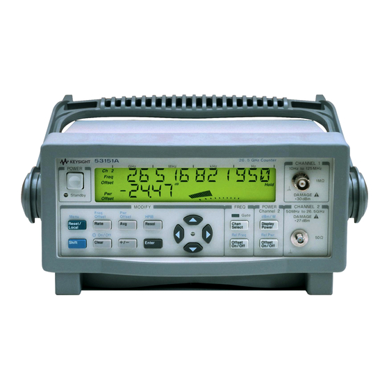
The Agilent 53150A, 53151A, and 53152A Microwave Frequency Counters are capable of measuring frequencies from 10 Hz to 125 MHz on Channel 1 and from 50 MHz to 20 GHz (53150A), 26.5 GHz (53151A), and 46 GHz (53152A) on Channel 2. These frequency counters are also capable of measuring power on Channel 2 (in the same frequency ranges). -
Page 13: Options
5-year Return to Agilent for Repair, Option W50 • 5-year Return to Agilent for Calibration, Option W52 5-year Return to Agilent for Standards Compliant Calibration, • Option W54 Retrofit • Options 001 and 002 can be installed only by authorized Agilent Technologies Repair Centers. Operating Guide xiii... -
Page 14: Accessories Supplied And Available
• Power cord, 2.3 meters (Part number dependent upon destination country) • Fuse (Agilent P/N 2110-0007) Accessories Available • Soft Carrying Case, (Agilent P/N 53150-80016) Automotive Power Adapter (Agilent P/N 53150-60214) • • Battery (Agilent P/N 53150-80010) • GPIB Cables (Agilent P/N 10833A/B/C/D) •... -
Page 15: Agilent 53150A/151A/152A Quick Reference Guide
Quick Reference Guide The Quick Reference Guide is designed for experienced users of the Agilent 53150A, 53151A, and 53152A. It is intended to be used as a tool to trigger your memory. If you are using the Counter for the first time, Agilent recommends that you at least read Chapter 1, “Getting... -
Page 17: Frequency Counter
Agilent 53150A/151A/152A Frequency Counter On/Off Clear Menu Reset/ Local REF OSC > INT PRESET REF OSC > < 00-111-222 > < SN 999999 > 53150A > <OPTNS -- -- -- -- > SAVE > 0 to 9 OP 9999 HRS RECALL >... - Page 18 QR-2...
-
Page 19: Getting Started
Getting Started... -
Page 20: The Front Panel At A Glance
Chapter 1 Getting Started The Front Panel at a Glance The Front Panel at a Glance 53150A 20 GHz Counter CHANNEL 1 10 Hz to 125 MHz POWER Ch 12 Rel Freq 1M Ω Offset Ext Rel Hold Avg On Rate Rmt SRQ Watts Rel Pwr... -
Page 21: The Front Panel Indicators At A Glance
Chapter 1 Getting Started The Front Panel Indicators at a Glance The Front Panel Indicators at a Glance The front panel includes three LED indicators. These are listed and described in the following table. Indicator Description The Standby indicator is lit whenever the Main ~ Power switch on the rear panel is turned ON, and the POWER switch on the front panel is OFF (out). -
Page 22: The Front Panel Menus At A Glance
Chapter 1 Getting Started The Front Panel Menus at a Glance The Front Panel Menus at a Glance Shift Menu Reset/ Local REF OSC > INT PRESET REF OSC > < 00-111-222 > < SN 999999 > 53150A > <OPTNS -- -- -- -- > SAVE >... -
Page 23: The Display Annunciators At A Glance
Chapter 1 Getting Started The Display Annunciators at a Glance The Display Annunciators at a Glance Ch 12 Rel Freq Offset Ext Rel Hold Avg On Rate Rmt SRQ Watts Rel Pwr Error Offset Shift Annunciator Description Ch 1 or Ch 2 Indicates which channel is selected to measure an input signal. -
Page 24: The Display Special Characters At A Glance
Chapter 1 Getting Started The Display Special Characters at a Glance The Display Special Characters at a Glance Special Description Characters Points to the current value for a Menu setting. Indicates that the value for the current Menu setting can be changed using the selection (arrow) keys. -
Page 25: The Rear Panel At A Glance
Chapter 1 Getting Started The Rear Panel at a Glance The Rear Panel at a Glance Made in U.S.A. ISM 1-A with domestic and foreign content OPTIONS 001 Oven Time Base 002 Battery Main ~ Power Reference 10 MHz Auxillary WARNING: To avold electric shock, do not remove covers. -
Page 26: Operating The Counter
Operating the Counter The procedures in this section are designed to familiarize you with the Frequency Counter’s features and controls. Agilent suggests that you follow the steps for each of these procedures, even if you do not presently need to make any measurements or to adjust any of the Counter’s settings. - Page 27 Chapter 1 Getting Started Operating the Counter The following legend defines the meanings of the icons used throughout this chapter. Legend Press key one Result Indicator off time and release Auto operation Indicator on Multiple key Connect signal Indicator flashing presses Disconnect signal Operating Guide...
-
Page 28: Turning The Counter On
Chapter 1 Getting Started Operating the Counter Turning the Counter On To turn on the Counter, turn on the Main ~ Power switch on the rear panel (see page 1-7), and then press and release the POWER button on the front panel. -
Page 29: Turning The Display Backlight Off Or On
Chapter 1 Getting Started Operating the Counter NOTE If a signal was applied to the Channel 2 input connector prior to turning on the Counter, CH2 NO SIGNAL is displayed momentarily. As soon as the Counter acquires the input signal, it displays the signal’s value. The internal Reference Oscillator requires 10 to 15 minutes to reach a NOTE stable operating temperature. -
Page 30: Using The Menu
Chapter 1 Getting Started Operating the Counter Using the Menu The Agilent 53150A/151A/152A Counter has one menu that you use to control a number of the Counter’s features and functions. Displaying the Menu To display the Menu, press the Shift key and then the Menu (Reset/Local) key, as shown below. - Page 31 Chapter 1 Getting Started Operating the Counter Ch 2 Freq Shift Shift Menu Reset/ Local Ch 2 Enter Ext Ref When you select the Menu, the indicator between the arrow keys flashes to indicate that the arrow keys are now active. Since the Reference Oscillator setting is the first one displayed when you invoke the Menu (unless you’ve used the Menu to change another setting since you turned the Counter on), you don’t have to use the...
- Page 32 (no settings are required [or possible] for these), such as Battery Voltage, Operation Hours, and information that identifies the Counter (Agilent model number, firmware version number, serial number, and installed option codes). These menu options and the ones described below are shown in “The Front Panel Menus at a Glance”...
-
Page 33: Setting The Serial Port Baud Rate (Menu Example)
Chapter 1 Getting Started Operating the Counter Setting the Serial Port Baud Rate (Menu Example) Ch 2 Freq Shift Shift Menu Reset/ Local Ch 2 Freq Enter Operating Guide 1-15... -
Page 34: Selecting The Input Channel
Chapter 1 Getting Started Operating the Counter Selecting the Input Channel You can toggle between Channels 1 and 2 by pressing the Chan Select key. Ch 1 Freq Chan Select Ch 2 Freq Chan Select 1-16 Operating Guide... -
Page 35: Measuring Frequency
Chapter 1 Getting Started Operating the Counter Measuring Frequency The following diagram shows the basic sequence to use to make a frequency measurement using Channel 1. This example assumes that the Counter is on and has completed the Self Test. For the purposes of this example, use the 10 MHz reference output on the Counter’s rear panel as a signal source for input to Channel 1. - Page 36 CAUTION The 2.9 mm Planar Crown* connector used for the Channel 2 input on the Agilent 53152A must be handled with care to prevent damage and/or contamination, especially since it acts as a wave guide as well as an electrical connection. Observe the following precautions when handling this connector: 1.
-
Page 37: Measuring Relative Frequency
Chapter 1 Getting Started Operating the Counter Measuring Relative Frequency You can measure the difference in frequency from one measurement to another (drift) using the Relative Frequency function. You do this by pressing the Shift and Rel Freq (Offset On/Off) keys as shown in the diagram below (this example assumes that a signal is currently applied to Channel 1). -
Page 38: Offsetting A Frequency Measurement
Chapter 1 Getting Started Operating the Counter Offsetting a Frequency Measurement You can use the Frequency Offset (Freq Offset) function to add or subtract a constant value to/from a frequency measurement. For example, you can use an offset to compensate for a systematic error or to display the difference in frequency between two signals. -
Page 39: Chapter 1 Getting Started
Chapter 1 Getting Started Operating the Counter Ch 2 Freq Ch 2 Freq Offset Offset On/Off Ch 2 Freq Shift Offset Shift Freq Offset Freq Rate Offset Freq Offset Freq Offset Ch 2 Freq Enter Offset Operating Guide 1-21... -
Page 40: Measuring Power (Channel 2 Only)
Chapter 1 Getting Started Operating the Counter Measuring Power (Channel 2 Only) The Agilent 53150A/151A/152A Counter can measure signal power (in the same frequency ranges as for frequency measurements) on Channel 2. The example procedure for measuring power in the following diagram assumes that the Counter has previously been set up to measure a 25 GHz input on Channel 2. -
Page 41: Selecting The Unit Of Measurement For Power
Chapter 1 Getting Started Operating the Counter Selecting the Unit of Measurement for Power The Counter’s power-measurement function can display values in either of two sets of units of measurement—dB and dBm or W, mW, and µW (the Counter automatically selects the most appropriate unit when either set of units is selected). -
Page 42: Measuring Relative Power
Chapter 1 Getting Started Operating the Counter Measuring Relative Power You can measure the difference in power from one measurement to another (drift) using the Relative Power function. You do this by pressing the Shift and Rel Pwr (Offset On/Off) keys, as shown in the diagram below (this example assumes that a signal is currently applied to Channel 2). - Page 43 Chapter 1 Getting Started Operating the Counter offset value is then entered. However, the order doesn’t matter, so you can also enter the offset value first, and then turn the offset function on. Ch 2 Freq Rel Pwr Ch 2 Freq Offset On/Off...
-
Page 44: Using Power Correction
Chapter 1 Getting Started Operating the Counter Using Power Correction The Power Correction function in the main Menu allows you to set the Counter to automatically compensate for power loss (or gain) that occurs in the test configuration, such as attenuation resulting from cable impedance. You can choose from nine power-correction profiles that are stored in nonvolatile memory, and you can modify the contents of these profiles. -
Page 45: Increasing Profile Accuracy
Chapter 1 Getting Started Operating the Counter As the graph shows, the Counter never computes power-correction values NOTE for loss above the zero axis. Conversely, corrections are never computed for gain below the zero axis. Once the correction value reaches the zero axis, no further corrections are applied. -
Page 46: Selecting A Power-Correction Profile
0.0 dB loss at the highest frequency the Counter can measure (20 GHz for the 53150A, 26.5 GHz for the 53151A, or 46 GHz for the 53152A). The remaining eight data points contain values of 0.0 dB loss at 0.0 GHz. - Page 47 Chapter 1 Getting Started Operating the Counter Ch 2 Freq Ch 2 Freq Shift Shift Menu Reset/ Local Ch 2 Freq Enter Shift NOTE When Power Correction is enabled, a lower-case letter “c” is displayed in the hundredths position of the power display. Operating Guide 1-29...
- Page 48 Chapter 1 Getting Started Operating the Counter 1-30 Operating Guide...
- Page 49 Chapter 1 Getting Started Operating the Counter Pressing the Enter key after entering values exits the Menu and restores NOTES the measurement display. To remain in the Power Correction menu so you can enter or change values in another data point in the currently selected, press the left-arrow key repeatedly (after entering the values for a data point) until “PWR CORR”...
-
Page 50: Setting The Measurement Rate
Chapter 1 Getting Started Operating the Counter Setting the Measurement Rate The measurement rate determines how frequently the Counter takes measurements. You can set the measurement rate to FAST, MED (medium), SLOW, or HOLD (single measurement taken each time you press the Reset/Local key). -
Page 51: Setting The Number Of Averages
Chapter 1 Getting Started Operating the Counter Setting the Number of Averages You can set the number of measurements the Counter takes and averages before displaying the result. The default setting is one (no average computations are performed when the number of averages is set to one), and the maximum setting is 99. -
Page 52: Setting The Resolution
Chapter 1 Getting Started Operating the Counter For most of the Counter’s settings, when you continue to press either the NOTE up-arrow or the down-arrow key when you reach the end of the available settings, the value for the setting “rolls over” to the value at the opposite end of the range. - Page 53 Chapter 1 Getting Started Operating the Counter Ch 2 Freq Resol Ch 2 Freq Enter Operating Guide 1-35...
- Page 54 Chapter 1 Getting Started Operating the Counter 1-36 Operating Guide...
-
Page 55: Operating Your Frequency Counter
Operating Your Frequency Counter... -
Page 56: Introduction
Chapter 2 Operating Your Frequency Counter Introduction Introduction This chapter contains information and usage procedures for the front-panel keys, operating functions, and menus of the Agilent 53150A/151A/152A Microwave Frequency Counter. Chapter Summary • How this Counter Works for You pg. 2-3 Summary of the Measurement Sequence pg. -
Page 57: How This Counter Works For You
Chapter 2 Operating Your Frequency Counter How this Counter Works for You How this Counter Works for You The following is a list of some of the key things the Counter does for you. • Presets the menus to default states and values at power-up •... -
Page 58: Summary Of The Measurement Sequence
Chapter 2 Operating Your Frequency Counter Summary of the Measurement Sequence Summary of the Measurement Sequence 1. Turn on the Main ~ Power switch on the back panel, and then press and release the POWER button on the front panel. NOTE The internal Reference Oscillator receives power only when the Main ~ Power switch is on. -
Page 59: Using The Selection Keys
Chapter 2 Operating Your Frequency Counter Using the Selection Keys Using the Selection Keys There are six Selection keys—four “arrow” keys, the Enter key, and the sign (+/–) key. The functions of the arrow keys depend on the Counter’s operating mode (i.e., sequencing through choices in the Menu, numeric entry, state change, etc.). -
Page 60: Numeric Entry
Chapter 2 Operating Your Frequency Counter Using the Selection Keys Numeric Entry Several menu functions, and several functions that have dedicated keys on the front panel, require you to enter numeric values. • Press the (left-arrow) and (right-arrow) keys to move left and right to select adjustable digits (the selected digit flashes). -
Page 61: Changing States
Chapter 2 Operating Your Frequency Counter Using the Selection Keys Changing States Several menu functions, and several functions that have dedicated keys on the front panel, require you to choose from a list of available states. These functions and the states you can choose for each of them are: •... - Page 62 Chapter 2 Operating Your Frequency Counter Using the Selection Keys Use the Selection keys as described below to change the state of these functions: When the annunciator ( ) in the display flashes, press the right-arrow • key to move the focus from the displayed menu function (or front- panel-key function) to the setting for that function.
-
Page 63: Using The Clear And Reset/Local Keys
Chapter 2 Operating Your Frequency Counter Using the Clear and Reset/Local Keys Using the Clear and Reset/Local Keys The Clear key and the Reset/Local key have similar functions in the Menu and in other front-panel-key function settings, but their effects vary with the Counter’s state and condition. -
Page 64: Other Function Selection Keys
Chapter 2 Operating Your Frequency Counter Other Function Selection Keys Other Function Selection Keys There are several functions that you access directly from front-panel keys (not from within the Menu). These functions are: MODIFY Measurement Rate (Rate key) • Freq GPIB Offset Offset... - Page 65 Chapter 2 Operating Your Frequency Counter Other Function Selection Keys • Relative frequency measurement (Rel Freq). Press Shift, and then press the Rel Freq (Offset On/Off) key to measure the difference in frequency between the current measurement and the measurement taken at the time you pressed the Rel Freq key (drift).
-
Page 66: Measuring Frequency
Chapter 2 Operating Your Frequency Counter Measuring Frequency Measuring Frequency Connect the Counter to a power source, and set the Main ~ Power switch on the back panel to 1 (on). Main ~ Power If the Counter is connected to an AC power source, the Main AC Power indicator on the back panel and the Standby indicator on the front panel light. - Page 67 Chapter 2 Operating Your Frequency Counter Measuring Frequency When the frequency of a signal applied to the Channel 2 input exceeds the NOTE maximum rated frequency for the instrument, the Counter displays CH2 TOO HIGH. To measure the frequency of a signal applied to the Channel 1 input, press the Chan Select key.
-
Page 68: Setting The Resolution And The Measurement Rate
Chapter 2 Operating Your Frequency Counter Setting the Resolution and Measurement Rate Setting the Resolution and Measurement Rate The number of measurements the Counter makes in a given amount of time is affected by the Rate setting, the Resolution setting, and the quality of the input signal (signal quality affects the amount of time the Counter requires to determine an accurate measurement). -
Page 69: Resolution Setting Example
Chapter 2 Operating Your Frequency Counter Setting the Resolution and Measurement Rate Resolution Setting Example For the following example, use the 10 MHz output from the reference timebase as the input to Channel 1. Press the Resol key to enter the resolution-setting mode. GPIB The current resolution setting is displayed (the current value and the Resol... -
Page 70: Setting The Measurement Rate
Chapter 2 Operating Your Frequency Counter Setting the Resolution and Measurement Rate Setting the Measurement Rate The measurement Rate setting determines how frequently the counter initiates measurements. Since the actual measurement rate is also affected by the resolution setting and the signal quality, as mentioned earlier, the available rate settings (FAST, MED, and SLOW) do not equate to a fixed number of measurements in a given amount of time.The HOLD setting turns off automatic measurements, so that a single measurement... -
Page 71: Setting The Number Of Averages
Chapter 2 Operating Your Frequency Counter Setting the Number of Averages Setting the Number of Averages You can set the Counter to take a variable number of frequency, power, or voltage measurements and average them mathematically before displaying the result. You can use this feature to determine the effective measurement of a signal that is fluctuating. - Page 72 Chapter 2 Operating Your Frequency Counter Setting the Number of Averages For most of the Counter’s settings, when you continue to press either the NOTE up-arrow or the down-arrow key when you reach the end of the available settings, the value for the setting “rolls over” to the value at the opposite end of the range.
- Page 73 Chapter 2 Operating Your Frequency Counter Setting the Number of Averages In certain situations, the length of time that the AVERAGING message is displayed can be affected by additional factors. When you are measuring frequency, the current resolution setting, the rate setting, and the quality of the signal all affect the length of time required to make the measurements and complete the average computation.
-
Page 74: Measuring Relative Frequency
Chapter 2 Operating Your Frequency Counter Measuring Relative Frequency Measuring Relative Frequency You can measure the difference in frequency from one measurement to another (frequency drift) or between two separate input signals using the Relative Frequency function. Relative Frequency Example Press the Shift key, and then press the Rel Freq (FREQ Offset On/Off) key. -
Page 75: Offsetting A Frequency Measurement
Chapter 2 Operating Your Frequency Counter Offsetting a Frequency Measurement Offsetting a Frequency Measurement You can use the Frequency Offset (Freq Offset) function to add or subtract a constant value to/from a frequency measurement. For example, you can use an offset to compensate for a systematic error or to display the difference in frequency between two signals. - Page 76 Chapter 2 Operating Your Frequency Counter Offsetting a Frequency Measurement Use the left- and right-arrow keys to move the focus to the digit(s) in the frequency-offset display that you need to adjust to enter the offset value, and then use the up- and down-arrow keys to adjust the value for each digit.
- Page 77 Chapter 2 Operating Your Frequency Counter Offsetting a Frequency Measurement Press the Offset On/Off key. The Freq Offset annunciator is activated, and the value of the display is adjusted to reflect the value and sign of the offset entered in Steps 2 and 3. The display should look like this: Ch 1 Freq...
-
Page 78: Measuring Power
Chapter 2 Operating Your Frequency Counter Measuring Power Measuring Power The Agilent 53150A/53151A/53152A can also measure signal power (in the same frequency ranges as for frequency measurements) on Channel 2. The power measurement, which is shown in a dedicated area of the display, includes a digital readout and an analog representation that is useful when peaking signals. - Page 79 Chapter 2 Operating Your Frequency Counter Measuring Power Press the Shift key, and then press the dBm/W (Display Power) key. When you press the Shift key, the Shift annunciator is activated. When you press the dBm/W (Display Power) key, the Shift annunciator goes off, and the units of measurement annunciator group to the right of the digital power measurement changes from dB or dBm to W, mW, or µW, as shown below: Ch 12...
-
Page 80: Measuring Relative Power
Chapter 2 Operating Your Frequency Counter Measuring Relative Power Measuring Relative Power You can measure the difference in power from one measurement to another or between two separate input signals using the Relative Power function. Relative Power Example Press the Shift key, and then press the Rel Pwr (PWR Offset On/Off) key. The Shift annunciator activates when you press the Shift key. -
Page 81: Offsetting A Power Measurement
Chapter 2 Operating Your Frequency Counter Offsetting a Power Measurement Offsetting a Power Measurement You can use the Power Offset (Pwr Offset) function to add or subtract a constant value to/from a power measurement. For example, you can use an offset to compensate for a systematic error, to display the difference in power between two signals, or to compensate for losses and attenuation in cables or components that are between the signal source and the Counter. - Page 82 Chapter 2 Operating Your Frequency Counter Offsetting a Power Measurement Press the Shift key, and then press the Pwr Offset (Avg) key. The Shift annunciator activates when you press the Shift key. When you press the Pwr Offset key, the Shift annunciator and the frequency display disappear, the Pwr Offset annunciator at the left side of the display activates, and the power offset value is set to 00.00, as shown below: Ch 12...
- Page 83 Chapter 2 Operating Your Frequency Counter Offsetting a Power Measurement Press the Enter key to confirm the offset value and exit the offset- entry display. The Pwr Offset annunciator is deactivated, and the measurement display returns. Press the Offset On/Off key (in the POWER area of the front panel). The Pwr Offset annunciator is activated, and the value of the display is adjusted to reflect the value and sign of the offset entered in Steps 3 and 4.
-
Page 84: Using Power Correction
0.0 dB loss at 1 GHz, and 0.0 dB loss at the highest frequency the Counter can measure (20 GHz for the 53150A, 26.5 GHz for the 53151A, or 46 GHz for the 53152A). The remaining eight data points contain values of 0.0 dB loss at 0.0 GHz. -
Page 85: Power Correction Theory Of Operation
Chapter 2 Operating Your Frequency Counter Using Power Correction Power Correction Theory of Operation When the Counter interpolates between data points to determine the amount of correction to apply to the current measurement, it computes the correction based on a straight line plotted between the frequency values in the two closest data points. -
Page 86: Increasing Profile Accuracy
Chapter 2 Operating Your Frequency Counter Using Power Correction Since there can be no further change in the loss or gain values once the zero axis is reached, no power corrections are applied when the input frequency reaches or passes a point in the profile that intersects the zero axis. -
Page 87: Power Correction Example: Selecting A Correction Profile
1 GHz and 0.0 dB loss at the highest frequency the Counter can measure (20 GHz for the 53150A, 26.5 GHz for the 53151A, or 46 GHz for the 53152A). The remaining eight data points in each of the profiles initially contain values of 0.0 dB loss at 0.0 GHz. - Page 88 Chapter 2 Operating Your Frequency Counter Using Power Correction Press the Enter key to select profile number 3. Power Correction is enabled using profile number 3, and the measurement display returns. The power reading now includes an adjustment for the loss incurred at the measured frequency.
-
Page 89: Power Correction Example: Editing Data Point Values
Chapter 2 Operating Your Frequency Counter Using Power Correction Power Correction Example: Editing Data Point Values Select a power-correction profile using the up- and/or down-arrow keys (as shown in steps 1 through 4 in the previous example). For this example, choose profile number 3. Press the right-arrow key. - Page 90 00.0 dB loss at 1.0 GHz and 00.0 dB loss at the highest frequency the Counter can measure (20 GHz for the 53150A, 26.5 GHz for the 53151A, or 46 GHz for the 53152A). The remaining data points contain values of 00.0 dB loss at 00.0 GHz. In profiles that have...
- Page 91 Chapter 2 Operating Your Frequency Counter Using Power Correction Use the right-arrow key to move to each of the remaining digits in the frequency setting, and use up- and down-arrow keys to adjust their values, if necessary. The currently selected digit flashes to indicate that it is the one that changes when you press the up- and down-arrow keys.
- Page 92 Chapter 2 Operating Your Frequency Counter Using Power Correction To add or adjust the values in another data point, press the left-arrow key repeatedly until “PWR CORR” is re-displayed, and repeat steps 2 through 10. To edit data points within another power-correction profile, press the left-arrow key repeatedly until “PWR CORR”...
-
Page 93: Using The Menu
Using the Menu Using the Menu The Agilent 53150A/151A/152A Counter’s Menu makes it easy to control a number of the Counter’s features and functions. You use the Selection (arrow) keys to navigate to the setting you want to change and then to actually make the changes. - Page 94 Chapter 2 Operating Your Frequency Counter Using the Menu Press the Enter key to activate the setting and exit the Menu. The setting you chose is put into effect, and the Menu closes. If you need to exit the Menu without changing any of the settings, press the Clear key.
-
Page 95: Navigating In The Menu And Changing Settings
Chapter 2 Operating Your Frequency Counter Using the Menu • SAVE — Saves a copy of the current user settings in non-volatile memory. Nine sets (0 – 8) can be saved, and set 0 is automatically read on startup. To have the Counter automatically start up with your preferred settings, save these settings in set 0. -
Page 96: Reference Oscillator (Ref Osc)
(no settings are required [or possible] for these), such as Battery Voltage, Operation Hours, and information that identifies the Counter (Agilent model number, firmware version number, serial number, and installed option codes). These menu options are described in the remainder of this chapter and also in “The Front Panel Menus at a... -
Page 97: Do Self Test
Counter has been in operation since its last calibration. This value does not include Standby hours. This information is useful for scheduling routine maintenance and calibration. For additional information on maintenance and calibration, see the Agilent 53150A/151A/152A Assembly-Level Service Guide. Model Number, Firmware Version, Serial Number, and... - Page 98 Using the Menu VVV is the version number of the Counter’s firmware, and XX, YYY, and ZZZZ are other numerical codes that are reserved for Agilent internal use. The flashing annunciators at either end of the first line of the display indicate that you can use the equivalent arrow key to scroll left and/or right to the next field of information.
-
Page 99: Preset
Chapter 2 Operating Your Frequency Counter Using the Menu Preset When PRESET is displayed, pressing the Enter key loads the default settings for most of the Counter’s functions. These functions and their default settings are listed in the following table: Table 2-1. -
Page 100: Serial Port Data Rate (Baud)
Chapter 2 Operating Your Frequency Counter Using the Menu RS-232 Serial Port Data Rate (BAUD) The Baud rate for the RS-232 serial port is configurable at 2400, 4800, 9600, 14,400, and 19,200 bps. The default setting is 9600 bps. Frequency Modulation (FM) The Counter can measure signals that are modulated in frequency, such as a microwave radio carrier. - Page 101 Specifications...
-
Page 102: Specifications Introduction
Chapter 3 Specifications Introduction Introduction The specifications of the Agilent 53150A, 53151A, and 53152A are provided in this chapter. Operating Guide... - Page 103 Chapter 3 Specifications Measurement Specifications and Characteristics All measurement specifications are over the full signal and temperature ranges unless otherwise noted. Input Characteristics Agilent 53150A Agilent 53151A Agilent 53152A Frequency Range 10 Hz–125 MHz 10 Hz–125 MHz 10 Hz–125 MHz Channel 1 (Normal mode) 10 Hz–50 kHz...
- Page 104 Chapter 3 Specifications Input Characteristics Agilent 53150A Agilent 53151A Agilent 53152A Emissions (“kickback noise”) Channel 1 −40 dBm/<−70 dBm −40 dBm/<−70 dBm −40 dBm/<−70 dBm Channel 2 (measuring/no input) Residual Stability* Channel 1 0.6 LSD rms 0.8 LSD rms 1.25 LSD rms...
- Page 105 Chapter 3 Specifications Typical* power measurement uncertainty at 25°C for various input levels Graph 1. −10 dBm input level at 25°C. Graph 2. 0 dBm and −20 dBm input * Typical means approximately 2/3 of all units will meet these characteristics. Operating Guide...
- Page 106 Chapter 3 Specifications Typical* power measurement uncertainty at −25 dBm input level Graph 3. −25 dBm input level at 25°C. Graph 4. −25 dBm input level from * Typical means approximately 2/3 of all units will meet these characteristics. Operating Guide...
- Page 107 Chapter 3 Specifications Timebase Power Supply ac: 90–132 Vac; 47.5–66 Hz or 360–440 Hz Frequency: 10 MHz Output: 10 MHz sine wave, 1 Vrms into 50 Ω 216–264 Vac; 47.5–66 Hz line selection: automatic External Timebase Input: 1, 2, 5, 10 MHz; 1 to 5 Vrms into 50 Ω...
- Page 108 Chapter 3 Specifications Operating Guide...
- Page 109 Rack Mounting the Counter...
-
Page 110: Rack Mounting The Counter Rack Mounting The Counter
You can mount the Counter in a standard 19-inch cabinet using one of two optional kits available from Agilent: • Option 1CM Rack Mount Kit (Agilent 53150-67001 Rack Adapter Kit) for single instrument (Half Module) rack mounting. Instructions and mounting hardware are included with the rack-mounting kit. - Page 111 To rack-mount the Counter by itself, perform the steps shown in the following illustration. (Refer to the instructions that are provided with the Rack Adapter Kit for details.) 1 Rack Flange 3 Agilent 53150A/151A/152A Counter 2 Handle Pivot 4 Panel Filler (Adapter) Assembly Operating Guide...
- Page 112 To rack-mount the Counter with another instrument side-by-side, obtain the 5061-9694 Lock Link Kit. (Refer to the instructions that are provided with the Lock Link Kit for details.) 1 Lock Links 4 Agilent 53150A/151A/152A Counter 2 Rack Flange 5 Second Agilent 53150A/151A/152A Counter or other half-rack-size instrument...
- Page 113 Messages...
-
Page 114: Operating Guide
Appendix B Messages Overview Overview The Agilent 53150A/151A/152A provides two types of messages that are displayed on the Counter’s front panel and/or sent over the RS-232 serial interface. The first type is status messages, which are displayed during normal operation. The second type is error messages, which are sent via RS-232 and/or displayed when the Counter detects an error during the Self-Test procedure or during normal operation. -
Page 115: Self-Test Messages
Appendix B Messages Self-Test Messages Self-Test Messages Table 3-2 lists and describes messages that are generated by the Counter during Self-Test to indicate whether a component passed or failed its test. These messages are sent via the RS-232 serial output only—they do not appear on the Counter’s front-panel display. - Page 116 Appendix B Messages Error Messages Error Messages Table 3-3 lists and describes messages that are generated by the Counter during Self-Test or during operation to indicate that a problem has been detected. These messages are displayed on the Counter’s front-panel display and are also sent via the RS-232 serial output (note that, in many cases, the exact message text that is displayed on the front panel is a condensed form of the message that is sent via RS-232).
- Page 117 Appendix B Messages Error Messages Table B-3. Error Messages (continued) Message Display RS-232 Description FRONT PANEL FAIL The front panel or its interconnecting cable are defective or not properly FPANEL FAIL connected. FPGA FAIL A failure was detected in the FPGA (Field Programmable Gate Array).
-
Page 118: Error Messages
Appendix B Messages Error Messages Operating Guide... -
Page 119: Using The Battery Option
Using the Battery Option... -
Page 120: Overview
Standby mode.) You can also charge the batteries outside the Counter using an AC or suitable DC power source and the optional External Charger (Agilent P/N 53150-60217). Operating the Counter from the Batteries When the Counter is powered from the internal batteries, it operates in... -
Page 121: Operating The Counter From A Dc Power Source
Appendix C Using the Battery Option Operating the Counter from a DC Power Source When all three segments of the battery annunciator are activated, the battery charge level is at 83% or more. When only two segments are activated, the charge level is approximately 50%, and when only the first segment is activated, the charge level is approximately 17%. -
Page 122: Replacing The Batteries
Counters equipped with the Battery option use sealed lead-acid VHS camcorder batteries. You can obtain additional batteries of this type from Agilent (Agilent P/N 53150-80010) and from other suppliers who carry test equipment and/or video camera accessories. Removing the Batteries... -
Page 123: Installing Batteries
Appendix C Using the Battery Option Replacing the Batteries The thumbscrews require a considerable amount of turning force, since NOTE they pull the battery sled partially out of the Counter and also extract the battery terminals from the battery connector as you turn them. To prevent the battery sled from binding and increasing the force necessary to turn the thumbscrews, either turn both thumbscrews simultaneously, or alternately turn the thumbscrews one-half turn each, until both... - Page 124 Appendix C Using the Battery Option Replacing the Batteries fe re w it ti c d fo x il la re ig te n a tt e ry o ld e le t re c tr e r- L IN ll s e rv ic e...
- Page 125 Appendix C Using the Battery Option Replacing the Batteries Holding one of the batteries so the battery terminals are to your right and the plus sign at the terminal end is facing away from you, insert the left-hand end of the battery into the taller end of the battery sled with the far side of the battery against the far side of the sled.
-
Page 126: Charging The Batteries
In general, it takes approximately eight hours to charge two batteries inside the instrument. The Agilent part numbers for the batteries are provided in the section titled “Accessories Supplied and Available” on page xiv. Operating Guide... -
Page 127: Precautions
Appendix C Using the Battery Option Precautions Precautions Observe the following precautions when handling and charging the batteries: • Do not attempt to use or charge the batteries when they are exposed to temperatures below –10º C (15º F) or above 40º C (105º F). (Most batteries of this type have an internal safety device that prevents them from operating outside of this temperature range.) •... - Page 128 Appendix C Using the Battery Option Precautions C-10 Operating Guide...
- Page 129 Index SYMBOLS AVERAGING 2-18 2-19 (Freq Offset) 1-20 Avg key 2-10 2-17 2-45 (Resol key) 2-45 Avg On 2-18 AC Input/Power module backlight 1-11 Accessories BATT VOLTAGE 2-40 Available batteries 2-43 Supplied battery annunciator Acknowledging Messages battery chamber analog Battery compartment analog power display 2-24 Battery Option...
- Page 130 Index operating the Counter from a DC Connector power source External Reference operating the Counter from the cooling fan batteries rechargeable batteries data points 2-30 2-33 removing the batteries data rate 2-40 replacing the batteries dB, dBm 2-24 battery sled dBm/W key 2-25 2-45...
- Page 131 Index Electro-Static Discharge 1-17 factory default settings 2-40, 2-45 electro-static discharge prevention procedure 1-17 FAST 2-16 Enter key 1-14 firmware 2-44 Error Firmware Version 2-43 Error Messages firmware version number 1-14 2-12 –12V FAIL 2-40 2-42 12V FAIL flash rate 2-14 2-15 –5V FAIL...
- Page 132 Index Display Power / dBm/W key Display Power key 2-10 Gate indicator 2-14 2-15 2-16 Enter key Gate LED Indicator Freq Offset key flash rate FREQ Offset On/Off key 2-10 measurement rate Gate indicator Gate LED indicator Gate LED indicator Gater LED Indicator GPIB key 2-10...
- Page 133 Index serial number 1-14 using 1-12 LCD display 1-11 menu 1-12 1-13 backlight 1-11 Menu (Reset/Local) key 1-12 LED Display menu function Annunciator Menu key 2-39 2-41 left pointer menu options 2-42 Legend messages icons minimum battery voltage 2-43 1-23 minimum effective charge Lock Link Kit Model Number...
- Page 134 Index Operating the Counter from a DC measuring power 2-24 Power Source Option Codes 2-43 Operating the Counter from the option codes 1-14 2-42 Batteries optional Oven Timebase 2-42 Operation Options xiii acknowledging messages Battery changing states Hardware xiii displaying the Menu 1-12 Oven Timebase 2-42...
- Page 135 Index Power Offset 1-24 1-25 2-45 Main Power On indicator Power Offset (POWER Offset On/Off Main Power switch key) 2-45 RJ12 connector Power Offset Example 2-27 RS-232 Interface connector Power Offset function 1-24 2-27 Rear Panel at a Glance Power offset measurement 2-10 RECALL 2-40...
- Page 136 Index resolution 2-14 Service Resolution (Resol) key 2-45 Repackaging for Shipment Resolution / GPIB key Setting the Measurement Rate 1-32 2-16 Resolution setting 2-14 Setting the Number of Averages 2-17 resolution setting 2-14 2-15 2-16 Setting the Resolution 2-14 Resolution Setting Example 2-15 Setting the Resolution and the right pointer...
- Page 137 Index Unit of Measurement 1-23 units of measurement annunciator group 2-25 user setting 2-40 Using Power Correction 2-30 Using the Clear and Reset/Local Keys Using the Menu 2-39 Using the Selection Keys version number 2-44 W, mW, uW 2-24 Operating Guide Index-9...
- Page 138 Index Index-10 Operating Guide...
- Page 139 Technical Support: If you need technical assistance with an Agilent test and measurement product or application, you can find a list of local service representatives on the web site listed above. If you do not have access to the Internet, one of the following centers...
- Page 140 Continued from front matter. . . Warranty (cont’d) Agilent will be liable for damage Safety Considerations For continued protection to tangible property per incident against fire, replace the line (cont’d) Agilent does not warrant that up to the greater of $300,000 or...
-
Page 141: Declaration Of Conformity
Canada: CSA C22.2 No. 1010.1:1992 July 31, 2001 Date Art Nanawa Product Regulations Manager For further information, please contact your local Agilent Technologies sales office, agent or distributor. Authorized EU-representative: Agilent Technologies Deutschland GmbH, Herrenberger Straβe 130, D 71034 Böblingen, Germany SA... - Page 142 DC.fm Page 2 Monday, July 22, 2002 10:51 AM...