
Related Manuals for Agilent Technologies 53220A


Summary of Contents for Agilent Technologies 53220A
- Page 1 Agilent 53220A/53230A 350 MHz Universal Frequency Counter/ Timer User’s Guide Agilent Technologies...
-
Page 2: Declaration Of Conformity
Agilent Technologies Sales and Ser- any form or by any means (including elec- Technology Licenses vice office for further information on Agilent tronic storage and retrieval or translation Technologies' full line of Support Programs. into a foreign language) without prior agree-... -
Page 3: Safety Information
Do not install substitute parts or perform any unauthorized modification to the prod- Ground the Instrument uct. Return the product to an Agilent Sales and Service Office for service and repair to The Agilent 53220A/53230A is provided ensure that safety features are maintained. -
Page 4: Safety Symbols
Installing the Instrument the indicated conditions are fully injury. understood and met. The Agilent 53220A/53230A operates in the following line-voltage ranges: WARN IN G WARN IN G 100 - 240V, 50-60 Hz 100 - 127V, 440 Hz... -
Page 5: Table Of Contents
Applying Power 18 Power-On LED Status 19 Standby Power 19 Battery Operation 20 Battery Care 22 Using Built-In Help 23 Utility Functions 23 Display Configuration 23 User Interaction 27 Reference Settings 28 How the User’s Guide is Organized 32 53220A/53230A User’s Guide... - Page 6 Contents 53220A/53230A Software Installation and Interface Configuration 35 Software Requirements 36 Using the Counter Web-Enabled Interface 37 Connecting the Counter and Viewing its Home Page 37 Web Interface Overview 39 Installing the Agilent IO Libraries 41 Installing Instrument Drivers 43...
- Page 7 Continuous 110 Burst Pulse Measurements 112 Carrier Frequency 113 Pulse PRI and PRF 114 Positive and Negative Widths 117 4 53220A/53230A Input Signal Conditioning 119 Channel Characteristics 120 Signal Conditioning Path 120 Input Impedance 122 Input Range 124 Input Coupling 126...
- Page 8 Advanced Gate Control - Gate Start 177 Advanced Gate Control - Gate Stop Hold Off and Gate Stop 182 Automatic Gate Extension 189 53220A/53230A Math, Graphing, and Data Logging 191 Math Functions 192 Enabling the CALCulate1 Subsystem 193 Smoothing Data 194...
- Page 9 Creating Folders and Files in Flash Memory and on the USB Drive 249 User-Defined Power-On States 258 Managing Folders and Files 261 8 Instrument Status 267 Agilent 53220A/53230A Status System 269 Questionable Data Register Group 269 Standard Operation Register Group 270 Standard Event Register 272...
- Page 10 Contents 53220A/53230A User’s Guide...
-
Page 11: Preparation For Use
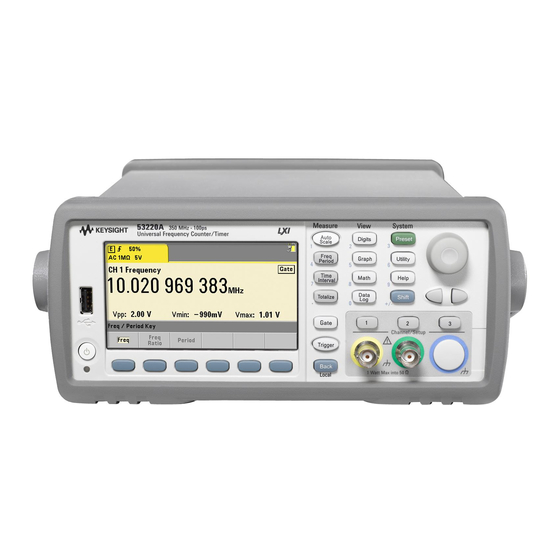
Welcome. This user’s guide contains configuration and operating information for the Agilent 53220A/53230A 350 MHz Universal Counter/Timer. The 53220A/53230A is a 2U, 1/2-module width LXI Class C instrument. The 2U, 1/2-module width references refer to the 53220A/53230A’s physical size relative to standard EIA rack cabinet dimensions. LXI, an acronym for LAN... - Page 12 Opt 010 UOCXO Opt 106/115 Opt 300 Battery Opt 150 sw (53230A Only) Line 100-240V, 50-60 Hz 100-127V, 400 Hz Int Ref Out Trig In ISM 1-A 90VA Max Intertek Figure 1-1. The 53220A/53230A Universal Frequency Counter/Timer. 53220A/53230A User’s Guide...
-
Page 13: Front And Rear Panel Overview
Preparation for Use Front and Rear Panel Overview Figure 1-1 shows the front and rear panels of the Agilent 53230A 350 MHz Universal Frequency Counter/Timer. The 53220A and the 53230A are dimensionally identical and available with the same product options - with the exception of Pulse Measurement Firmware Option 150 available with the 53230A only. -
Page 14: Rear Panel
Trig In - is the connector for supplying an external trigger signal to the counter. Triggering is covered in Chapter 5. D. USB and LAN - are the standard input/output (I/O) ports. Configuration of these ports and the GPIB interface is covered in Chapter 2. 53220A/53230A User’s Guide... -
Page 15: Display
Preparation for Use Display The layout of the 53220A/53230A display is shown in Figure 1-2. Status Indicators Input Settings RMT: remote (LAN, USB, GPIB) operation : measurement start edge ExtRef: external frequency reference 10% : trigger threshold : input coupling (ac or dc) - Page 16 Opt. 400: GPIB Interface Each of the product options listed in Table 1-1 is available after the original purchase of the N O TE instrument. Refer to the 53210A/53220A/53230A Service Guide (p/n 53220-90010) for installation instructions for each of these options. No Manuals? There are three printed manuals available with the 53220A/53230A: •...
-
Page 17: Operating And Storage Environments
Preparation for Use 53220A/53230A Option 0B0 (delete printed manuals) is the default product documentation option. If Option 0B0 was ordered, only the Quick Start Tutorial and 53210A/53220A/53230A Product Reference CD-ROM are shipped with the instrument. All manuals are available on the CD. To obtain printed manuals from Agilent, contact your Agilent representative. -
Page 18: Electrical Requirements
For additional information, refer to the Safety Information pages at the beginning of this N O TE guide. For a complete list of 53220A/53230A product specifications, refer to the data sheet included on the 53210A/53220A/53230A Product Reference CD (p/n 53220-13601), or on the Web at: www.agilent.com/find/53220A... -
Page 19: Power-On Led Status
AC power is available to the instrument and that the power cord is securely connected. If the instrument still does not turn on, the cooling fan is not audible, or if the front panel display is off when power is applied, return the unit to Agilent for repair. -
Page 20: Battery Operation
Under battery power, the instrument chassis may float to the potential of the measured signal supplied by the user. With Battery Option 300 installed and enabled, the 53220A/53230A counter can be operated using battery power for up to three hours. - Page 21 1-2). Remotely, the instrument can be queried as to whether it is currently using AC power or battery power with the command: SYSTem:BATTery:STATus? The command returns AC if the instrument is using line power, or BATT if using the internal battery. 53220A/53230A User’s Guide...
-
Page 22: Battery Care
AC power must be applied to recover from a shut down caused by this condition. For a complete list of battery and all 53220A/53230A product specifications, refer to the N O TE... -
Page 23: Using Built-In Help
• user interaction - localized language selection, audible indicators • reference settings - time/date, measurement time out, time base, auto-leveling, 53100 series emulation, NISPOM security Display Configuration Measurements can be displayed in numerical or graphical form using the following keys. 53220A/53230A User’s Guide... - Page 24 When Graph is selected, the data is displayed in a trend chart or histogram. Trend charts and histograms are covered in Chapter 6. Numeric Format The format (radix, decimal group separator) of numeric data that appears in the main measurement display (Figure 1-2) is set using the following keys. 53220A/53230A User’s Guide...
- Page 25 Screen control is available through the keys shown below. The display screen can be turned off to increase reading throughput and its screen saver mode can be used to conserve power. Screen brightness can be adjusted for optimal viewing in different environments. 53220A/53230A User’s Guide...
- Page 26 Note that pressing any key with the display turned off, turns the display back Screen Capture For documentation of product testing or as a convenience in gathering data, the contents of the counter display can be captured and saved. The keys related to this feature are shown below. 53220A/53230A User’s Guide...
-
Page 27: User Interaction
Selecting the Instrument ‘Help’ language Programming messages, context-sensitive help, and other help topics are viewable in six languages. The selected language remains “active” until changed using the key sequence shown. Note that menu soft key labels appear only in English. 53220A/53230A User’s Guide... -
Page 28: Reference Settings
Note that the beeper setting does not apply to the tone heard when front panel keys are pressed. Reference Settings Reference settings are counter settings that apply to all counter measurements. Date and Time 53220A/53230A User’s Guide... - Page 29 Time Out” in Chapter 3 for more information. Time Base 53220A and 53230A measurements are based on a reference oscillator - also referred to as an internal/external clock or time base. A valid reference oscil- lator signal must be present for measurements to occur.
- Page 30 The minimum frequency at which auto-leveling can occur is set as shown. Slow sets the minimum frequency for auto-leveling at 50 Hz. Fast sets the minimum frequency for auto-leveling at 10 kHz. Refer to “Threshold Level and Sensitivity” in Chapter 4 for additional information on using auto-level. 53220A/53230A User’s Guide...
- Page 31 (query form) - language selects the SCPI command set used. Specifying 53132A enables the emulation mode. Specifying either 53220A or 53230A disables the mode. With 53100-series compatibility mode selected, all programming is through the counter's remote interface (LAN, USB, GPIB). The counter display responds according to the remote commands received.
-
Page 32: How The User's Guide Is Organized
(LAN, USB, GPIB) interface. As such, most topics include a front panel key sequence followed by the corresponding SCPI commands. For example: --------------------------------------------------------------------------------------------------------- The input impedance of the 53220A/53230A counter can be set to either 50 or 1 M using the command: INPut[{1|2}]:IMPedance {<impedance>|MINimum|MAXimum|... - Page 33 For general reference, the information in this manual is organized as shown in Figure 1-3. Signal Conditioning Triggering / Gating Chapter 4 Chapter 5 Measurements Math and Graphs Chapter 3 Chapter 6 Status Conditions Formats / Data Flow Chapter 8 Chapter 7 Figure 1-3. 53220A/53230A User’s Guide Organization. 53220A/53230A User’s Guide...
- Page 34 Preparation for Use 53220A/53230A User’s Guide...
-
Page 35: 53220A/53230A Software Installation And Interface Configuration
Downloading IVI-COM Driver Updates This chapter contains information on IO libraries, drivers, and interfaces used to program the 53220A/53230A from selected development environments. The chapter includes an introduction to using the counter’s web-enabled interface and provides information on updating the instrument firmware. -
Page 36: Software Requirements
IVI-COM -Web LAN, GPIB, USB National Instruments LabVIEW 53220A/53230A native mode driver IVI-C - Web LAN, GPIB, USB National Instruments LabWindows/CVI IVI-C - Web * Visit www.agilent.com for the latest version of the Agilent IO Libraries Suite. 53220A/53230A User’s Guide... -
Page 37: Using The Counter Web-Enabled Interface
This section describes the Web pages and windows primarily used to program the N O TE 53220A/53230A. Refer to “Help with this Page” associated with each Web page for additional information on functions or pages not covered in this manual. - Page 38 53220A/53230A Software Installation and Interface Configuration Enter the IP address in the browser’s address window. With “Advanced infor- mation ...” selected, the counter’s Web home page should appear as shown in Figure 2-1. Browser Configuration In some network configurations a proxy server may prevent access to the instrument (i.e.
-
Page 39: Web Interface Overview
Although no additional libraries or drivers are required to use the Web interface, the N O TE interface is also accessible from Agilent Connection Expert (ACE). See “Opening the Web Interface from Agilent Connection Expert” for more information. Web Interface Overview The following information is an introduction to the counter’s Web interface. - Page 40 53220A/53230A Software Installation and Interface Configuration Web interface pages other than the ‘Welcome Page’ may be password protected. When N O TE shipped from the factory no password is set; however, an ‘Enter Password’ dialog box may appear. Click on the dialog box to continue.
-
Page 41: Installing The Agilent Io Libraries
53220A/53230A in Microsoft development environments (Table 2-1). The VISA and VISA-COM libraries allow you to send commands from the 53220A/53230A SCPI command set to the instrument. The IO librar- ies also include Agilent Connection Expert described and used later in this chapter. - Page 42 N O TE Architecture) is currently installed on your computer, continue installation of the Agilent IO Libraries by installing Agilent VISA in side-by-side mode. More information on side-by-side operation can be found in IO Libraries Suite Help (available after installation is complete) under “Using Agilent’s and Other Vendors’...
-
Page 43: Installing Instrument Drivers
(e.g. IVI-COM, IVI-C)can be installed. Adding Instruments to the PC Interface During installation of the Agilent IO Libraries, the IO interfaces (LAN, USB, GPIB) detected on the PC are configured. This section contains information for programmatically adding the 53220A/53230A to those interfaces using the Agilent IO Libraries ‘Connection Expert’... -
Page 44: Configuring The Lan Interface
Once the IP address is known, start the Connection Expert utility by clicking the ‘Agilent IO Control’ icon and selecting “Agilent Connection Expert” from the pop up menu as shown in Figure 2-3. 53220A/53230A User’s Guide... - Page 45 Figure 2-3. Starting Agilent Connection Expert. Locating the Instruments Agilent Connection Expert opens with a welcome screen and window similar to that shown in Figure 2-4. The computer interfaces configured during instal- lation are displayed in the left column (Explorer pane), the properties of the configured interface are displayed in the right column (Properties pane).
- Page 46 53220A/53230A Software Installation and Interface Configuration configured interfaces Figure 2-4. Agilent Connection Expert Interface Window. Using the Sockets Protocol For higher performance, instruments added to the LAN configuration can also use the Sockets protocol. To use this connection, select ‘Add Address’ from the ‘Add Instruments’ menu (Figure 2-4). In this window, enter the instrument’s host name or IP address and under ‘Optional Socket Con-...
- Page 47 If there is a DHCP server on the network, the server will assign the address to the instrument. If there is not a DHCP server on the network, the 53220A/53230A will auto- matically determine the address to use. The address will be in the range 169.254.1.1 to 169.254.255.255.
- Page 48 53220A/53230A Software Installation and Interface Configuration Host Names The 53220A/53230A has a default host name. The format of the host name is: A-53220A-nnnnn (Agilent 53220A) A-53230A-nnnnn (Agilent 53230A) where ‘nnnnn’ are the last five digits of the instrument’s serial number.
-
Page 49: Configuring The Usb Interface
Type B USB connector located on the instrument rear panel. The first time the 53220A/53230A is connected to the PC via the USB cable, a N O TE “hardware wizard” utility within the PC may start and prompt you for installation software for the product. - Page 50 53220A/53230A Software Installation and Interface Configuration The USB Address String When programming the 53220A/53230A over USB, the instrument’s USB address is included in the address string as follows: USB0::2391::1287::0123456789::0::INSTR To simplify addressing during programming, a VISA alias can be assigned and used in place of the complete address.
- Page 51 53220A/53230A Software Installation and Interface Configuration Figure 2-6. Setting a VISA Alias for the USB Address String. Disabling the USB Interface The USB interface can be disabled from the front panel by selecting I/O Config, followed by USB Settings, and then USB Off. When disabling or enabling the USB interface, you must cycle power for the change to take affect.
-
Page 52: Configuring The Gpib Interface
N O TE on your computer. Programming access to the 53220A/53230A is also available through the GPIB interface. GPIB cables can be connected to the PC in a “star” (all cables connect directly to the computer) or “linear” (instrument to instru- ment) configuration. - Page 53 53220A/53230A Software Installation and Interface Configuration Figure 2-7. Selecting the GPIB Address. The counter’s GPIB address can be read from the front panel as shown below. 53220A/53230A User’s Guide...
- Page 54 53220A/53230A Software Installation and Interface Configuration The GPIB Address String When programming the counter over GPIB, the instrument’s GPIB address is included in the address string as shown below: GPIB0::3::INSTR Changing the GPIB Address To change the GPIB address, select GPIB Address and using the rotary knob or Shifted numeric keys, set the desired address.
-
Page 55: Using Interactive Io
Using Interactive IO The Connection Expert ‘Interactive IO’ utility provides another method (Table 2-1) of sending commands to the 53220A/53230A. Interactive IO is accessible from any of the PC’s IO interfaces, and allows you to send any command in the 53220A/53230A SCPI command set to the instrument. -
Page 56: Firmware And Driver Updates
If the Interactive IO window is used to send the self-test (*TST?) command to the N O TE 53220A/53230A, the “timeout” period may have to be increased to allow the results to be returned. This is done using the ‘Options’ tab on the Interactive IO window. -
Page 57: Scpi Language Emulation Mode
53220A/53230A Software Installation and Interface Configuration SCPI Language Emulation Mode If the 53220A/53230A is sometimes used in 53132A SCPI language (emulation) mode, the instrument must be returned to its original (53220A/53230A) mode before the firmware can be updated. Downloading and Installing the Update Utility 53220A/53230A firmware updates are installed in the instrument using the Agilent update utility. -
Page 58: Downloading The Firmware Update
53220A/53230A Software Installation and Interface Configuration Downloading the Firmware Update Return to the Web page and under ‘Documents & Downloads’ select: 532x0A Firmware Update Revision <revision number> When prompted, select ‘Run’ to download (save) the file to your PC. Note the directory location as you will need to specify the path to the firmware file when you run the update utility. - Page 59 53220A/53230A Software Installation and Interface Configuration 2. Press Next and using the Browse button, specify the path to the firmware file (Figure 2-10). Once specified, the instrument model number will appear in the ‘Applicable Models’ window along with the revision and instrument descrip- tion.
- Page 60 53220A/53230A Software Installation and Interface Configuration Figure 2-11. Specifying the Address or Host Name. The firmware update takes a few moments to complete. The 53220A/53230A will reboot once the update is complete. Following a firmware update, Agilent Connection Expert (if running) may report N O TE that the 53220A/53230A configuration has changed.
-
Page 61: Downloading Ivi-Com Driver Updates
53220A/53230A Software Installation and Interface Configuration Downloading IVI-COM Driver Updates IVI-COM and LabVIEW drivers for the 53220A/53230A (when available) are provided on the Web at either: www.agilent.com/find/53220A www.agilent.com/find/53230A Once this page is displayed, select the ‘Technical Support’ tab and then select ‘Drivers and Software’. - Page 62 53220A/53230A Software Installation and Interface Configuration 53220A/53230A User’s Guide...
-
Page 63: 53220A/53230A Measurements
Rise Time and Fall Time Pulse Width Duty Cycle Phase Single-Period Totalizing Measurements Gated Continuous Burst Pulse Measurements This chapter contains general programming information and examples of the measurements that can be made with the 53220A and 53230A counters. Agilent Technologies... -
Page 64: Counter Measurement Summary
53220A/53230A Measurements Counter Measurement Summary The Agilent 53220A and 53230A counter measurements are summarized in Table 3-1. The table includes the front panel keys under which specific mea- surements are selected via soft-keys. Also provided are the equivalent SCPI commands and channel restrictions. - Page 65 53220A/53230A Measurements Table 3-1. Agilent 53220A/53230A Measurement Summary (Cont’d) Instrument Channels Measurement Command CONFigure:TINTerval Time Interval Time 53220A / 53230A MEASure:TINTerval? Interval CONFigure:RTIMe Rise TIme Time 53220A / 53230A MEASure:RTIMe? Interval CONFigure:FTIMe Fall Time Time 53220A / 53230A MEASure:FTIMe? Interval...
-
Page 66: Reference Oscillator Configuration
53220A/53230A Measurements Reference Oscillator Configuration 53220A and 53230A measurements are based on a reference oscillator - also referred to as an internal/external clock or time base. A valid reference oscil- lator signal must be present for measurements to occur. The following information applies to the counter’s standard temperature com- pensated crystal oscillator (TCXO) and Option 010 Ultra High-Stability oven-controlled crystal oscillator (OCXO) references. - Page 67 The reference oscillator source is set to INTernal with automatic selection enabled (On) when the counter is shipped from the factory or following the SYSTem:SECure:IMMediate command. Settings are stored in non-volatile memory and are not changed after a reset (*RST) or instrument preset (SYSTem:PREset or Preset key). 53220A/53230A User’s Guide...
- Page 68 ExtRef will appear in the top, right corner of the display when a valid (external) reference is present. If a valid frequency is not present or was not specified, the message “No valid external timebase” is displayed. The error is also logged in the error queue. 53220A/53230A User’s Guide...
- Page 69 The error queue can be read from the front panel as follows: The status of the external reference (time base) is also monitored by the counter’s Questionable Data register. The register can be queried with the command: 53220A/53230A User’s Guide...
-
Page 70: Standby Power To The Reference Oscillator (Option 010)
With standby power Off, cycling power on the instrument also cycles power to the oscillator. This may affect the oscillator’s calibrated accuracy, and sta- bility may not occur until the specified warm-up time (45 minutes) is reached. 53220A/53230A User’s Guide... -
Page 71: Setting The Measurement Mode
RECiprocal - configures the counter for reciprocal-only measurements. In Reciprocal mode, the period of the input signal is measured and all frequency readings are derived from (are the reciprocal of) the period measurement. RECiprocal mode is not available on optional channel 3. 53220A/53230A User’s Guide... - Page 72 (1s) gate closed gate open Gate In/Out BNC: firmware controlled – will see fluctuations OUTput:STATe ON on the output BNC but readings are continuous (gap free) OUTput:POLarity NORMal Figure 3-1. 53230A Continuous, Gap-Free Measurement Sequence. 53220A/53230A User’s Guide...
- Page 73 CONTinuous mode is available on channels 1 and 2 and optional channel 3 of the 53230A only, and only for frequency and average-period measurements. Following a reset (*RST) or instrument preset (SYSTem:PREset or Preset key), the measurement mode is set to AUTO. CONFigure and MEASure do not change the mode. 53220A/53230A User’s Guide...
-
Page 74: Setting The Measurement Time Out
(Chapter 5) should be considered when setting an optimum time out value. The time out setting is stored in non-volatile memory and is not changed fol- lowing a reset (*RST) or instrument preset (SYSTem:PREset or Preset key). 53220A/53230A User’s Guide... -
Page 75: Scpi Syntax Conventions
Separating Commands and Parameters and Linking SCPI Commands A space must separate the last keyword and the first parameter. Commas (,) separate multiple parameters. The ‘@’ symbol must precede each counter channel number and parentheses must enclose each channel: MEAS:FREQ:RAT? 5E6,(@2),(@1) 53220A/53230A User’s Guide... - Page 76 In a command string containing both IEEE 488.2 common commands (e.g. *RST, *WAI, *OPC?) and SCPI instrument commands, the common commands are separated from the SCPI commands by a semicolon (;). An example is shown in the following string: CALC:STAT ON;AVER:STAT ON;:INIT;*WAI;:CALC:AVER:AVER? 53220A/53230A User’s Guide...
-
Page 77: The Measure And Configure Commands
AUTO for frequency, frequency ratio, average SENSe:FREQuency:MODE period, PRF, or PRI measurements. Unchanged for all others. Trigger source IMMediate TRIGger:SOURce Trigger slope NEGative TRIGger:SLOPe Trigger delay 0.0 seconds TRIGger:DELay Trigger count 1 trigger TRIGger:COUNt Sample count SAMPle:COUNt 1 sample 53220A/53230A User’s Guide... - Page 78 Measurement Timeout SYSTem:TIMeout Unchanged Reference oscillator SENSe:ROSCillator:SOURce Unchanged from previous settings. SENSe:ROSCillator:SOURce:AUTO SENSe:ROSCillator:EXTernal:FREQuency Reading Format FORMat Subsystem Unchanged from previous settings. Data Storage DATA Subsystem Unchanged from previous settings. Instrument Status STATus Subsystem Unchanged from previous settings. 53220A/53230A User’s Guide...
-
Page 79: Using Measure
The MEASure:FREQuency? command cannot be used since it immediately triggers a measurement after setting the trigger source to ‘internal’, the trigger count to ‘1’, and the sample count to ‘1’. The gate time is set to 0.1 seconds. 53220A/53230A User’s Guide... - Page 80 CONF? returns (including quotes): "FREQ +1.00000000000000E+006,+1.00000000000000E-004,(@2)" which includes the function, expected value, (calculated) resolution, and channel. If a channel number is not specified in the CONFigure or MEASure command, no channel is included in the return string. 53220A/53230A User’s Guide...
-
Page 81: Frequency And Period Measurements
53220A/53230A Measurements Frequency and Period Measurements The 53220A/53230A measurements covered in this section include frequency, frequency ratio, and period. The SCPI commands listed in these examples are provided as an introduction to N O TE how frequency measurements are made. Commands may be included even though they specify default values - but which should be considered when modify- ing the examples for actual use. - Page 82 *RST // reset to start from known state CONF:FREQ 20E6, 0.1, (@1) SAMP:COUN 10 // take 10 readings READ? Notes 1. See Chapter 5 for information on triggering and number of readings per trig- ger (sample count). 53220A/53230A User’s Guide...
-
Page 83: Frequency Ratio
- expected is the expected ratio of the two input signals. resolution is the desired resolution of the ratio measurement. The parameter ranges are: expected (Ch1/Ch2, Ch2/Ch1): 2.8E-10 to 3.5E+9 expected (Ch1/Ch3, Ch2/Ch3 - Option 106): 1.6E-11 to 3.5 expected (Ch1/Ch3, Ch2/Ch3 - Option 115): 6.6E-12 to 1.2 53220A/53230A User’s Guide... - Page 84 See “Frequency Measurements” in Chapter 5 for information on the relationship between gate time and reading resolution. 2. See Chapter 4 for additional information on counter threshold levels and on configuring the input signal path. 53220A/53230A User’s Guide...
-
Page 85: Period
(channels 1 and 2): 2.8 nsec to 10 sec (default = 100 nsec) expected (channel 3 Option 106): 160 psec to 10 nsec (default = 2 nsec) expected (channel 3 Option 115): 66 psec to 3.33 nsec (default = 2 psec) 53220A/53230A User’s Guide... - Page 86 READ? Notes 1. See Chapter 5 for information on triggering and number of readings per trig- ger (sample count). 2. See Chapter 4 for additional information on counter threshold levels and on configuring the input signal path. 53220A/53230A User’s Guide...
-
Page 87: Time Stamp
Figure 3-5. (Time stamp measurements are available with the 53230A only.) scale factor = 1 scale factor = 10 event time stamp time stamp time stamp scale factor = 2 Figure 3-5. Time Stamp Events on the Counter Channel. 53220A/53230A User’s Guide... - Page 88 // 1 MHz time stamp rate INIT // initiate and take readings *WAI // wait for readings to complete // transfer readings from reading memory to a file in the // root folder on the USB storage device MMEM:STOR:DATA RDG_STORE, "USB:\ts_data.csv" 53220A/53230A User’s Guide...
- Page 89 (e.g. 1.10077637E-06 / 11 = 1.00070579E-7). 3. See Chapter 4 for additional information on counter threshold levels and on configuring the input signal path. 4. See Chapter 7 for information on data flow, reading memory, and on creat- ing data files. 53220A/53230A User’s Guide...
-
Page 90: Time Interval Measurements
53220A/53230A Measurements Time Interval Measurements The 53220A/53230A time interval measurements covered in this section include one and two channel time interval, rise/fall time, pulse width, duty cycle, phase, and single period. The SCPI commands listed in these examples are provided as an introduction to N O TE how time interval measurements are made. - Page 91 (@1),(@2) | (@2),(@1) | (@1)|(@2) The input channel(s) are (default) configured for auto-leveling at 50% with a positive slope. When configuring time interval measurements consider the start or stop input thresholds, input slope, or gate stop hold off settings: 53220A/53230A User’s Guide...
- Page 92 1, and stops on a positive edge on channel 2. 2. A gate stop hold off is specified to select the desired rising edge on channel 2 and, therefore, the interval to be measured. 53220A/53230A User’s Guide...
- Page 93 1. Input coupling and impedance are set to assure the intended start and stop trigger thresholds as the thresholds are specified as absolute values. The mea- surement starts on the positive (rising) edge on channel 1, and stops on the negative (falling) edge. 53220A/53230A User’s Guide...
-
Page 94: Rise Time And Fall Time
An example of rise and fall times on an input signal are shown in Figure 3-8. + width - width frequency Figure 3-8. Rise Time and Fall Time Measurements. The commands used to make rise and fall time measurements are: MEASure:RTIMe? [{<lower_ref>|MINimum|MAXimum|DEFault} [,{<upper_ref>|MINimum|MAXimum|DEFault}]] [,<channel>] CONFigure:RTIMe [{<lower_ref>|MINimum|MAXimum|DEFault} [,{<upper_ref>|MINimum|MAXimum| DEFault}]] [,<channel>] 53220A/53230A User’s Guide... - Page 95 - channel is counter channel 1 or 2 specified as (@1) or (@2). Rise and Fall Time Measurement Examples // using MEASure? - measure rise time using 20% and 80% // references *RST // reset to start from known state MEAS:RTIM? 20, 80, (@2) 53220A/53230A User’s Guide...
- Page 96 2. Absolute references are relative to the amplitude of the signal and must take into consideration the counter’s input coupling and impedance settings. 3. See Chapter 4 for information on configuring the input signal path which includes coupling and impedance. 53220A/53230A User’s Guide...
-
Page 97: Pulse Width
An example of positive and negative pulse widths are shown in Figure 3-9. + width - width frequency Figure 3-9. Positive and Negative Pulse Width Measurements. The commands used to make positive and negative pulse width measurements are: MEASure:PWIDth? [{<reference>|MINimum|MAXimum|DEFault}] [,<channel>] CONFigure:PWIDth [{<reference>|MINimum|MAXimum|DEFault}] [,<channel>] 53220A/53230A User’s Guide... - Page 98 - channel is counter channel 1 or 2 specified as (@1) or (@2). Positive and Negative Pulse Width Measurement Examples // using MEASure? - measure positive width at a 50% (0V) // reference *RST // reset to start from known state MEAS:PWID? 50, (@1) 53220A/53230A User’s Guide...
- Page 99 2. Absolute references are relative to the amplitude of the signal and must take into consideration the counter’s input coupling and impedance settings. 3. See Chapter 4 for information on configuring the input signal path which includes coupling and impedance. 53220A/53230A User’s Guide...
-
Page 100: Duty Cycle
(Figure 3-10). period + duty cycle - duty cycle Figure 3-10. Positive and Negative Duty Cycle Measurements. The commands used to make positive and negative duty cycle measurements are: 53220A/53230A User’s Guide... - Page 101 V or MV (millivolt) suffix: 100 MV or .1V (spaces allowed). If reference is omitted or specified in percent, auto-leveling is enabled. If specified in absolute voltage, auto-leveling is disabled - channel is counter channel 1 or 2 specified as (@1) or (@2). 53220A/53230A User’s Guide...
- Page 102 3. The measured duty cycle is a decimal representation of the ratio. For exam- ple, a 5% duty cycle reading might appear in the counter output buffer as: +5.105095730909666E-002 The same reading would appear in the display as: 5.1 Pct. 53220A/53230A User’s Guide...
-
Page 103: Phase
4. See Chapter 4 for information on configuring the input signal path and Chapter 5 for information on Triggering. Phase Phase measurements indicate the phase difference or shift between signals on counter channels 1 and 2 (Figure 3-11). phase Figure 3-11. Phase Measurement Between Two Channels. 53220A/53230A User’s Guide... - Page 104 // channels 1 and 2, display result as a value b etween 0 and // 360 degrees *RST // reset to start from known state CONF:PHAS (@1), (@2) FORM:PHAS POS // display result as a positive value READ? 53220A/53230A User’s Guide...
-
Page 105: Single-Period
Single-period measurements provide mea- surement of “single-shot” or one cycle events; and allow analysis of signal characteristics (e.g. jitter) that would otherwise be averaged out with standard (averaging) period measurements. The commands used to make single-period measurements are: 53220A/53230A User’s Guide... - Page 106 MEASure:PERiod? or CONFigure:PERiod commands. 2. Setting an absolute threshold level disables the counter’s auto-level func- tion. CONFigure and MEASure enable auto-leveling at 50% (0V). 3. See Chapter 4 for information on input signal conditioning, including threshold level and sensitivity. 53220A/53230A User’s Guide...
-
Page 107: Totalizing Measurements
Commands may be included even though they specify default values - but which should be considered when modifying the examples for actual use. Refer to the ‘Programmer’s Reference’ on the Agilent 53210A/53220A/ 53230A Product Reference CD for additonal information. - Page 108 - gate_time specifies the time input events on the counter channel are total- ized. The range for gate_time is: 53220A: 100 s to 1000s (10 s resolution) or +9.9E+37 (INFinity) 53230A: 1 to 1000s (1 s resolution) or +9.9E+37 (INFinity) The default gate_time for both instruments is 0.100s.
- Page 109 Setting a hold off of 1 second in effect, sets a 1 second gate time. If the gate stop was not held off, the gate would close after 1 event. 2. See Chapter 5 for additional information on triggering and gating. 53220A/53230A User’s Guide...
-
Page 110: Continuous
- channel is counter channel 1 or 2, specified as (@1) or (@2). (There is no equivalent MEASure? command for continuous totalizing measurements.) The command: [SENSe:]TOTalize:DATA? can be used during continuous totalizing or with long gate times to read the current count. 53220A/53230A User’s Guide... - Page 111 2. Continuous totalizing must be aborted (stopped) before the count can be retrieved from the output buffer using the FETCh?, DATA:LAST?, DATA:REMove?, or R? command (Chapter 7). 3. The ABORt command sent from the remote interface or changing the counter function from the front panel stops continuous totalizing. 53220A/53230A User’s Guide...
-
Page 112: Burst Pulse Measurements
- but which should be consid- ered when modifying the examples for actual use. Refer to the ‘Programmer’s Ref- erence’ on the Agilent 53210A/53220A/53230A Product Reference CD for additonal information. For further information on microwave measurements, see Application Note 200-1 “Fundamentals of Microwave Frequency Counters”... -
Page 113: Carrier Frequency
Figure 3-13. 53230A Microwave Pulse Measurements. Carrier Frequency The commands used to measure the carrier frequency of a burst pulse are: MEASure:FREQuency:BURSt? [<channel>] CONFigure:FREQuency:BURSt [<channel>] - channel is optional channel 3 specified as (@3). 53220A/53230A User’s Guide... -
Page 114: Pulse Pri And Prf
Pulse PRI and PRF The commands used to measure the pulse repetition interval (PRI) and pulse repetition frequency (PRF) (Figure 3-13) of a burst signal are: 53220A/53230A User’s Guide... - Page 115 The parameter ranges are: expected: 1 Hz - 10 MHz (default = 1 kHz) resolution: 1.0E-15 * expected to 1.0E-5 * expected (default resolution corresponds to a 0.1s gate time) - channel is counter channel 3 specified as (@3). 53220A/53230A User’s Guide...
- Page 116 1. See “Measurement Gate” in Chapter 5 for information on digits of resolution based on expected value and resolution parameter settings. 2. See “Burst Measurement Detector Threshold” in Chapter 4 for information on setting the threshold for pulse measurements. 53220A/53230A User’s Guide...
-
Page 117: Positive And Negative Widths
// measure the positive (on) width using CONFigure, set // a -12 dB detector threshold *RST // reset to start from known state CONF:PWID:BURS (@3) INP3:BURS:LEV -12 // set a detector threshold of -12 dB READ? -------------------------------------------------------- 53220A/53230A User’s Guide... - Page 118 CONF:NWID:BURS (@3) INP3:BURS:LEV -12 // set a detector threshold of -12 dB READ? Notes 1. See “Burst Measurement Detector Threshold” in Chapter 4 for information on threshold settings and its relationship to positive and negative width mea- surements. 53220A/53230A User’s Guide...
-
Page 119: 53220A/53230A Input Signal Conditioning
Agilent 53220A/53230A 350 MHz Universal Counter/Timer User’s Guide 53220A/53230A Input Signal Conditioning Channel Characteristics Signal Conditioning Path Input Impedance Input Range Input Coupling Bandwidth Limiting (Low-Pass) Filter Threshold Level and Sensitivity Burst Measurement Detector Threshold Noise Rejection (Hysteresis) Threshold Slope... -
Page 120: Channel Characteristics
53220A/53230A Input Signal Conditioning Channel Characteristics There are two, plus an optional third input channel on the 53220A/53230A counter. Product Option 201 adds parallel (additional) rear panel access to channels 1 and 2. Product Options 106 and 115 add a 6 GHz or 15 GHz third channel. - Page 121 IN P ut3:B U R St:LE Ve l IN P ut{1|2}:N R E Jec t IN P ut{1|2}:S LO P e{1|2 } Figure 4-1. 53220A/53230A Input Signal Conditioning. Table 4-1 is a summary of power-on/reset values for the signal conditioning. parameters.
-
Page 122: Input Impedance
53220A/53230A Input Signal Conditioning Input Impedance The input impedance of the 53220A/53230A counter can be set to either 50 or 1 M using the command: INPut[{1|2}]:IMPedance {<impedance>|MINimum|MAXimum| DEFault} INPut[{1|2}]:IMPedance? [{MINimum|MAXimum|DEFault}] (query form) The 50 1 M impedances allow for impedance matching (termination) and bridging applications respectively. - Page 123 53220A/53230A Input Signal Conditioning Input Protection The maximum input voltage (including any DC offset) allowed with 50 input impedance is 5.125 Vp. If the input voltage exceeds 10.0 Vp, the input protection relay opens - changing the input impedance to 1 M .. (The display and Impedance softkey will still indicate a 50 setting however.)
-
Page 124: Input Range
53220A/53230A Input Signal Conditioning Input Range The signal operating ranges (input ranges) of the 53220A/53230A counter are 5.0V, ± 50V,and ± 500V and are dependent on the probe factor. The range is set using the command: INPut[{1|2}]:RANGe {<range>|MINimum|MAXimum|DEFault} INPut[{1|2}]:RANGe? [{MINimum|MAXimum|DEFault}](query form) When a 1:1 probe factor is selected (see “Setting the Probe Factor), the avail-... - Page 125 53220A/53230A Input Signal Conditioning Setting the Probe Factor For better access to test points on the device under test (DUT), Agilent recom- mends its N2870A, N2873A, and N2874A Passive Probes for use with the 53220A/ 53230A counter. The 35 MHz (BW) N2870A 1:1 probe and the 500 MHz N2873A and 1.5 GHz N2874A 10:1 probes are popular accessories...
-
Page 126: Input Coupling
53220A/53230A Input Signal Conditioning Input Coupling The input to the 53220A/53230A counter is either DC (direct) coupled or AC (capacitive) coupled, and is set using the the command: INPut[{1|2}]:COUPling {AC|DC} INPut[{1|2}]:COUPling? (query form) AC coupling removes the signal’s DC content and centers the signal at 0V. The... -
Page 127: Bandwidth Limiting (Low-Pass) Filter
53220A/53230A Input Signal Conditioning input signal with DC offset trigger point programmed trigger level reset point Hysteresis window DC coupling AC coupling Figure 4-2. Using AC Coupling to Reach Trigger Points. Settling Time Between DC and AC Coupling There is an inherent settling time when changing from DC to AC coupling. As a measure of this time, a signal with a 5V DC component (DC coupled) will typi- cally center around 0V (AC coupled) in one second. - Page 128 53220A/53230A Input Signal Conditioning be enabled within the signal path to eliminate noise introduced by higher-fre- quency components of the input signal. The bandwidth filter is switched into the signal path using the command: INPut[{1|2}]:FILTer[:LPASs][:STATe] {OFF|ON} INPut[{1|2}]:FILTer[:LPASs][:STATe]? (query form) On - enables the filter. OFF - disables the filter.
-
Page 129: Threshold Level And Sensitivity
53220A/53230A Input Signal Conditioning Threshold Level and Sensitivity The threshold level is the trigger (input) level at which the counter begins the signal count (i.e. measurement). This level is the center of the hysteresis band - the band which represents counter sensitivity. For a count to occur, the sig- nal must cross the upper and lower limits of the band in opposite directions (polarities). - Page 130 53220A/53230A Input Signal Conditioning Specifying an Absolute Threshold Level The input threshold level can be specified as an absolute value. An absolute level is set with the command: INPut[{1|2}]:LEVel[{1|2}][:ABSolute] {<volts>|MINimum| MAXimum|DEFault} INPut[{1|2}]:LEVel[{1|2}][:ABSolute]? [{MINimum|MAXimum| DEFault}] (query form) Absolute threshold levels for the input ranges are: •...
- Page 131 53220A/53230A Input Signal Conditioning If auto-leveling is enabled, querying the absolute level on the current measurement channel N O TE returns the corresponding threshold voltage. If the channel is not the measurement channel, 9.91E+37 (not a number) is returned. Level2 can only be queried for rise/fall time and single-channel time interval measurements.
- Page 132 53220A/53230A Input Signal Conditioning INPut[{1|2}]:LEVel[{1|2}]:RELative {<percent>|MINimum|MAX- imum|DEFault} INPut[{1|2}]:LEVel[{1|2}]:RELative? [{MINimum|MAXimum| DEFault}] (query form) Threshold values are from 10% to 90% with 5% resolution. In order to specify a relative threshold level, auto-level must be enabled. LEVel/LEVel1 sets the relative threshold for all measurements except rise/fall time and single-channel time interval.
- Page 133 53220A/53230A Input Signal Conditioning For frequencies in this range, use the CONFigure command and turn off auto-level by specifying an absolute threshold level. For example: //measure a 10 Hz signal CONF:FREQ 10, (@1) // measure 10 Hz signal INP:IMP 50...
- Page 134 53220A/53230A Input Signal Conditioning If a 30% relative threshold is specified for the DC-coupled signal described above, the corresponding (absolute) value is 1.4V. The same relative threshold for an AC-coupled signal has an absolute value of -0.6V. The absolute value of any relative threshold level can be queried using:...
- Page 135 53220A/53230A Input Signal Conditioning The frequency parameter values are: Frequencies Interface Frequencies > 10 kHz 50 Hz to < 10 kHz Front Panel Fast Slow 10.0E3 50.0 SCPI Maximum MINimum A frequency setting of 10 kHz decreases the auto-level period for all frequen- cies >...
-
Page 136: Burst Measurement Detector Threshold
53220A/53230A Input Signal Conditioning Burst Measurement Detector Threshold All 53230A burst measurements are relative to the pulse width. The ‘on’ por- tion of the pulse width is established by a -6 dB and -12 dB detector threshold. Figure 4-6 is an example of the thresholds relative to the peak amplitude of the burst signal. -
Page 137: Noise Rejection (Hysteresis)
53220A/53230A Input Signal Conditioning The detector threshold and, therefore, the ‘on’ portion of the pulse width must be considered when making burst measurements such as positive (on) width and negative (off) width. This threshold is set with the command: INPut3:BURSt:LEVel {<dB>|MINimum|MAXimum|DEFault}... - Page 138 53220A/53230A Input Signal Conditioning Threshold sensitivity (Figure 4-4) to the input signal is a function of the amount of noise rejection or hysteresis. Noise rejection (the hysteresis band) at the counter input is increased or decreased with the command: INPut[{1|2}]:NREJection {OFF|ON}...
-
Page 139: Threshold Slope
53220A/53230A Input Signal Conditioning Threshold Slope The slope (edge) of the input signal on which the threshold level occurs is specified with the command: INPut[{1|2}]:SLOPe[{1|2}] {POSitive|NEGative} INPut[{1|2}]:SLOPe{1|2}]? (query form) POSitive - the trigger point occurs on the positive (rising) edge. The reset point occurs on the negative (falling) edge (Figure 4-4). -
Page 140: Measuring Input Signal Levels And Signal Strength
53220A/53230A Input Signal Conditioning Input Slope Example //set the threshold slope CONF:FREQ 1E6, 0.1, (@1) // measure 1 MHz signal SYST:ALEV:FREQ 10E3 // set minimum auto-level frequency INP:IMP 50 // set impedance to 50 ohms INP:RANG 5 // set range to 5V... - Page 141 53220A/53230A Input Signal Conditioning The relative signal strength on channel 3 Option 106 or 115 (6 GHz or 15 GHz microwave input) is dislayed on the counter and can also be measured with the command: INPut3:STRength? The colors and the relative strengths returned by the command indicate the...
- Page 142 53220A/53230A Input Signal Conditioning 53220A/53230A User’s Guide...
-
Page 143: Triggering And Gating
Advanced Gate Control - Gate Stop Hold Off and Gate Stop Automatic Gate Extension 53220A/53230A counter measurements are made by triggering the instrument and gating the input signal to select the portion or duration during which the input signal is measured. -
Page 144: Settings Summary
Frequency burst gate delay 0.0s Frequency burst gate narrow Frequency burst gate time 1 us Time Interval Time interval gate source Immediate Time interval gate polarity Negative Totalize Totalize gate source Time Totalize gate time 0.1s Totalize gate polarity Negative 53220A/53230A User’s Guide... -
Page 145: Trigger And Gate Time Line
The SCPI commands and parameters listed throughout this chapter are provided N O TE as a guide to how the counter is operated programmatically. The commands are described in detail in the ‘Programmer’s Reference’ section of the Agilent 53210A/53220A/53230A Product Reference CD. 53220A/53230A User’s Guide... - Page 146 Sample Count INITiate:IMMediate Wait-for-trigger state READ? MEASure? triggers received TRIGger:COUNt? trigger received Triggered state # readings SAMPle:COUNt? (to gate cycle) (repeated for each reading in sample count) (from gate cycle) Figure 5-2. Trigger and Gate Cycle - Triggering. 53220A/53230A User’s Guide...
- Page 147 Gate stop source does not apply to rise/fall time, duty cycle, pulse width, phase, and (frequency and period measurements) single-period measurements Figure 5-2 (cont’d). Trigger and Gate Cycle - Gating. 53220A/53230A User’s Guide...
-
Page 148: System Trigger
*RST - resets the counter to its factory default values. The counter also returns to the idle state after the total number of measure- ments determined by the TRIGger:COUNt and SAMPle:COUNt settings are complete (i.e. # of measurements = TRIGger:COUNt x SAMPle:COUNt). 53220A/53230A User’s Guide... - Page 149 T rig g e r C o un t T R IG ger:C O U N t S a m ple C o u n t S AM Ple:C O U N t Figure 5-3. System Trigger Sequence. System Trigger Source 53220A/53230A User’s Guide...
- Page 150 //configure for frequency, set system trigger parameters CONF:FREQ 5E6,0.1,(@2) TRIG:SOUR EXT // trigger source external System Trigger Slope When the system trigger source is set to EXTernal, the triggering slope (edge) of the signal is set with the command: 53220A/53230A User’s Guide...
- Page 151 TRIGger:DELay? [{MINimum|MAXimum|DEFault}] (query form) - specifies the delay in seconds. Delays between subsequent measurements (i.e. multiple readings per trigger - see SAMPle:COUNt) are set with the SENSe:GATE:STARt:DELay commands. CONFigure and MEASure set a defaut delay of 0.0s. 53220A/53230A User’s Guide...
- Page 152 //configure for frequency, set system trigger parameters CONF:FREQ 5E6,0.1,(@2) TRIG:SOUR EXT // trigger source external TRIG:SLOP POS // external trigger slope - positive TRIG:DEL 1 // 1s delay after trigger received TRIG:COUN 2 // accept 2 system triggers 53220A/53230A User’s Guide...
- Page 153 TRIG:SOUR EXT // trigger source external TRIG:SLOP POS // external trigger slope - positive TRIG:DEL 1 // 1s delay after trigger received TRIG:COUN 2 // accept 2 system triggers SAMP:COUN 100 // take 100 rdgs for each trigger 53220A/53230A User’s Guide...
-
Page 154: Wait-For-Trigger And Triggered States
The trigger count is also ignored when making continuous, gap-free frequency or period measurements. Only one trigger is accepted when using these functions. See the ‘Programmer’s Reference’ section of the Agilent 53210A/53220A/53230A Product Reference CD for more information. Wait-For-Trigger and Triggered States In order for the counter to accept triggers which start the trigger and gate cycle, the counter must be initiated. - Page 155 TRIG:COUN 2 // accept 2 system triggers SAMP:COUN 100 // take 100 readings per system trigger READ? //initiate the counter - fetch readings from memory Once initiated, a valid trigger signal and a satisfied delay period (if specified) 53220A/53230A User’s Guide...
-
Page 156: Measurement Gate
The counter’s gate source determines the path through the gate cycle and the related parameters that must be considered. A gate source is required for all frequency, totalizing, and time interval measurements. Although selection of the gate source is shown at the beginning of the cycle 53220A/53230A User’s Guide... - Page 157 (or default) period of time. For applications requiring synchronization with external events or requiring more precise gate control, an external gate or advanced gating is used. Exter- 53220A/53230A User’s Guide...
-
Page 158: Frequency Measurements
Resolution and Gate Time Reading resolution (in digits) is a function of the counter’s gate time, measure- ment mode (AUTO, CONTinuous, RECiprocal - Chapter 3), and resolution enhancement algorithm. Resolution enhancement (R ), which is defined in the 53220A/53230A User’s Guide... - Page 159 AUTO or CONTinuous mode with gate times > 10 msec. Table 5-2 shows the digits of resolution achieved with the 53230A and 53220A for a given gate time. The table also includes formulas for estimating digits as a function of gate time or expected values, and gate times as a function of digits.
- Page 160 5 MHz signal is required. Because digits of resolution is approximately equal to Log (expected value) - Log (resolution), this measurement could be configured as: MEAS:FREQ? 5e6, 5E-4, (@1) // expected freq, resolution A typical measurement using this configuration might return: +4.99998458333282E+006 53220A/53230A User’s Guide...
- Page 161 MEAS:PER? 5E-9, 5E-15, (@1) // per meas of 200 MHz signal A typical measurement using this configuration might return: +5.00010899135045E-009 With the counter display registering: 5.000 10nsec (6 digits) Querying the gate time after sending this command returns: SENS:FREQ:GATE:TIME? +1.00000000000000E-005 (10 us - no resolution enhancement) 53220A/53230A User’s Guide...
- Page 162 External Gate Signal Polarity When using any external gate source the polarity of the gate signal and there- fore, the duration of the gate, is set or changed with the command: 53220A/53230A User’s Guide...
- Page 163 External Gate Signal Threshold For external sources INPut[1] and INPut2 (Chan 1 and Chan 2 softkeys), a fixed input threshold voltage must be specified in addition to the gate signal polarity. This is done using the command: 53220A/53230A User’s Guide...
- Page 164 The opposite edge (polarity) of the signal crossing the threshold closes the gate. (More information on the INPut subsystem can be found in Chapter 4 - “ 53220A/53230A Input Signal Conditioning”.) When using external sources INPut[1] and INPut2, the channel selected as the gate source cannot be the same channel on which the measured signal is applied.
-
Page 165: Totalizing
The command used to set or change the gate source is: [SENSe:]TOTalize:GATE:SOURce {TIME|EXTernal|INPut[1]| INPut2|ADVanced} [SENSe:]TOTalize:GATE:SOURce? (query form) - gate source TIME enables totalizing on the input channels for a specified period. Setting the Gate Time The gate time is set with the command: [SENSe:]TOTalize:GATE:TIME {<time>|MINimum|MAXimum| 53220A/53230A User’s Guide... - Page 166 “Enabling Gate Signals on the ‘Gate In/Out BNC” for more information and for information on using gate signals to synchronize other instruments. External Gate Signal Polarity When using the external gate sources, the polarity of the gate signal and there- 53220A/53230A User’s Guide...
- Page 167 (*RST) or instrument preset (SYSTem:PRESet or Preset key), the negative edge is selected. To set the polarity of the external gate signal: // select the gate polarity and source CONF:TOT:TIM SENS:TOT:GATE:POL POS // set polarity SENS:TOT:GATE:SOUR EXT // set source External Gate Signal Threshold 53220A/53230A User’s Guide...
- Page 168 SENS:TOT:GATE:SOUR INP1 // set source - channel 1 INP1:LEV 4 // set threshold - 4V Gate Source ADVanced Gate source ADVanced enables extended control of the gate signal through the counter’s SENSe:GATE commands (see Advanced Gate Control). 53220A/53230A User’s Guide...
- Page 169 TIME and the gate time to INFinity. The command also sets the input threshold to 0.0V and the edge (events that are totalized) to positive. Refer to Chapter 4 - “53220A/53230A Input Signal Conditioning” for information on the commands in the INPut subsystem used to change these parameters.
-
Page 170: Time Interval Measurements
(edge/level) are defined by the INPut subsystem. OUTput:STATe OFF must be set when using gate source EXTernal. See N O TE “Enabling Gate Signals on the ‘Gate In/Out BNC” for more information and for information on using gate signals to synchronize other instruments. 53220A/53230A User’s Guide... - Page 171 The following example shows configuration of a time interval measurement beginning with high-level configuration of the counter, setting up the start and stop events, and changing the polarity and gate source. //configure the counter for a time interval measurement //using external gating to start the measurement 53220A/53230A User’s Guide...
-
Page 172: Enabling Gate Signals On The 'Gate In/Out' Bnc
OUTPut:STATe OFF must be set when the gate source is EXTernal. NORMal - the polarity of the gate signal output from the "Gate Out" BNC is a rising (positive) edge. INVerted - the gate signal polarity is a falling (nega- tive) edge. 53220A/53230A User’s Guide... -
Page 173: Burst Carrier Frequency Measurements
Figure 5-6. ‘on’ time - 6 dB amplitude burst carrier frequency Figure 5-6. Burst Carrier Frequency (-6 dB threshold). See “Burst Measurement Detector Threshold” in Chapter 4 for more information N O TE on burst pulse characteristics. 53220A/53230A User’s Guide... - Page 174 OFF - disables narrow pulse mode. For ‘on durations’ greater than 20 s, nar- row pulse mode must be disabled. Following a reset (*RST) or instrument preset (SYSTem:PRESet or Preset key), narrow pulse mode is disabled. Carrier Frequency Gate Control 53220A/53230A User’s Guide...
- Page 175 - when ON, the gate time and delay are automatically configured based on the characteristics of the pulse signal. Following a reset (*RST) or instrument pre- set (SYSTem:PRESet or Preset key), automatic gate control is enabled (ON). When OFF, the gate time and delay are set manually using the commands: 53220A/53230A User’s Guide...
- Page 176 If the characteristics of the pulse are unknown, the “on time” can be measured separately to insure that the delay and time are set within the threshold detector’s sensitivity range (see Chapter 3 for more pulse measure- ment examples). // measure the on time of the burst to determine 53220A/53230A User’s Guide...
-
Page 177: Advanced Gate Control - Gate Start
Setting the gate source to ADVanced during configuration of frequency, total- izing, and time interval measurements enables additional (start/stop) control of the measurement gate. Figure 5-8 repeats the gate start source section of the full trigger/gate cycle shown in Figure 5-2. 53220A/53230A User’s Guide... - Page 178 SEN Se:GATE :STAR t:D ELay:SOU R ce IMM ediate (delay disabled) SEN Se:GATE:STAR t:DELay:EVEN ts (inp ut channel) SEN Se:GATE:STAR t:DELay:TIME Gate Start (open) Figure 5-8. Gate Start Sequence. Gate Start Source The specific command which sets the gate start (open) source is: 53220A/53230A User’s Guide...
- Page 179 Gate Signals on the ‘Gate In/Out BNC” for more information and for information on using gate signals to synchronize other instruments. External Gate Start Signal Polarity When using the external gate sources listed, the polarity of the start gate sig- nal is set (changed) with the command: 53220A/53230A User’s Guide...
- Page 180 For external sources INPut[1] and INPut2 (Chan 1 and Chan 2 softkeys), a fixed input threshold voltage must also be specified in addition to the gate sig- nal slope. This is done using the command: INPut[{1|2}]:LEVel[{1|2}][:ABSolute]{<volts>|MINimum| MAXimum|DEFault} INPut[{1|2}]:LEVel[{1|2}][:ABSolute]?[{MINimum|MAXimum| DEFault}] (query form) 53220A/53230A User’s Guide...
- Page 181 The specified edge (slope) of the gate signal crossing the threshold starts the gate. (More information on the INPut subsystem can be found in Chapter 4 - “53220A/53230A Input Signal Conditioning”.) When using external sources INPut[1] and INPut2, the channel selected as the gate source cannot be the same channel on which the measured signal is applied.
-
Page 182: Advanced Gate Control - Gate Stop Hold Off And Gate Stop
Advanced gate control also includes (optionally) enabling a gate stop hold off and setting the gate stop (close) parameters. Figure 5-9 repeats the gate stop hold off and gate stop sections of the full trigger/gate cycle shown in Figure 5-2. 53220A/53230A User’s Guide... - Page 183 For all other measurements or when specifying a hold off for a number of input events, the hold off begins on the first event after the gate opens (Figure 5-1). 53220A/53230A User’s Guide...
- Page 184 For two-channel time interval measurements, hold off events are counted on the ‘stop’ channel. For frequency ratio measurements, hold off events are counted on the ‘denominator’ channel. The number of events is specified with the command: [SENSe:]GATE:STOP:HOLDoff:EVENts {<count>|MINimum| MAXimum|DEFault} [SENSe:]GATE:STOP:HOLDoff:EVENts? (query form) 53220A/53230A User’s Guide...
- Page 185 (query form) Note for frequency, frequency ratio, average period, PRF, and PRI measure- ments, the minimum gate stop (close) holdoff time is 100 usec for the 53220A, or 1 usec for the 53230A. INFinity or +9.9E+37 is accepted only for the TOTalize measurement func- tion.
- Page 186 CONFigure and MEASure do not change the gate stop source setting. Follow- ing a reset (*RST) or instrument preset (SYSTem:PRESet or Preset key), gate stop source EXTernal is selected. 53220A/53230A User’s Guide...
- Page 187 1/channel 2 input. NEGative stops the measurement on a negative edge on the Gate In/Out BNC or channel 1/channel 2 input. CONFigure and MEASure do not change the slope setting. Following a reset (*RST) or instrument preset (SYSTem:PRESet or Preset key), a positive slope is selected. 53220A/53230A User’s Guide...
- Page 188 The specified edge (slope) of the gate signal crossing the threshold stops the gate. (More information on the INPut subsystem can be found in Chapter 4 - “53220A/53230A Input Signal Conditioning”.) When using external sources INPut[1] and INPut2, the channel selected as the gate source cannot be the same channel on which the measured signal is applied.
-
Page 189: Automatic Gate Extension
// initiate counter and take reading Automatic Gate Extension Inherent to 53220A/53230A frequency and period measurements is auto- matic gate extension in which the measurement ends one edge (event) of the input signal after the gate is closed (stopped). Thus, the sample count (SAMPle:COUNt) does not increment and cause a potential state change in the trigger/gate cycle (Figure 5-2) until the gate extension is complete. - Page 190 Triggering and Gating 53220A/53230A User’s Guide...
-
Page 191: 53220A/53230A Math, Graphing, And Data Logging
Data Logging Graphics Functions and Reading Memory The Agilent 53220A/53230A counter features math operations that allow you to scale readings, test limits, and statistically analyze data. Its graphics func- tions compute and display histograms and trend charts of real time measure- ment data. -
Page 192: Math Functions
The SCPI commands and parameters listed throughout this chapter are provided N O TE as a guide to how the counter is operated programmatically. The commands are described in detail in the ‘Programmer’s Reference’ section of the Agilent 53210A/53220A/53230A Product Reference CD. 53220A/53230A User’s Guide... -
Page 193: Enabling The Calculate1 Subsystem
53220A/53230A Math, Graphing, and Data Logging CALCulate1:AVERage:STATe ON CALCulate1:AVERage (statistics) CALCulate1:SCALe: STATe ON CALCulate1:LIMit:STATe ON CALCulate1:SMOothing:STATe ON INITiate:IMMediate CALCulate1:SMOothing CALCulate1:SCALe CALCulate1:LIMit reading memory (moving average) (scaling and offset) (limit checking) CALCulate2:TRANsform:HISTogram:STATe ON measurement data CALCulate1:STATe ON CALCulate2:TRANsform:HISTogram (histograms) READ? output buffer readings initiated by INITiate:IMMediate are sent to reading memory. -
Page 194: Smoothing Data
53220A/53230A Math, Graphing, and Data Logging A reset (*RST), instrument preset (SYSTem:PRESet), or changing the mea- surement function disables the CALCulate1 subsystem. Smoothing Data Measurements can be “smoothed” and scaled prior to performing math opera- tions on the incoming data. -
Page 195: Scaling Functions
53220A/53230A Math, Graphing, and Data Logging The number of readings to average is specified as: SLOW - 100 readings: with + 100 ppm change required to reset filter MEDium - 50 readings: with + 300 ppm change required to reset filter... - Page 196 CALCulate1:STATe ON CALCulate1:SCALe:STATe ON CALCulate1:SCALe:FUNCtion Figure 6-2. 53220A/53230A Display with Scaling Functions Enabled. Enabling the Scale Functions All 53220A/53230A scaling functions are enabled with the command: CALCulate[1]:SCALe[:STATe] {OFF|ON} CALCulate[1]:SCALe[:STATe]? (query form) ON enables scaling. OFF disables scaling. Following a reset (*RST) or instrument preset (SYSTem:PRESet), scaling is disabled.
- Page 197 53220A/53230A Math, Graphing, and Data Logging Using the Scale Functions The counter scaling functions include null, percent change (PCT), part per mil- lion change (PPM), part per billion change (PPB), and scale (Mx-B). The func- tion is selected with the command:...
- Page 198 53220A/53230A Math, Graphing, and Data Logging Scaling function results must be in the range of -1.0E+24 to -1.0E-24, 0.0, or +1.0E-24 to 1.0E+24. Results outside these limits will be replaced with -9.9E+37 (negative infinity), 0, or +9.9E+37 (positive infin- ity).
- Page 199 53220A/53230A Math, Graphing, and Data Logging Following a reset (*RST) or instrument preset (SYSTem:PRESet), a reference value of 0.0 is set and automatic reference is enabled. From the front panel, pressing Get New Reference takes a reference measure- ment on the first trigger received after the key is pressed. A reference can be entered manually by selecting Ref Value and using the knob or SHIFTed numeric keys.
- Page 200 53220A/53230A Math, Graphing, and Data Logging The offset value (B) is set with the command: CALCulate[1]:SCALe:OFFSet {<offset>|MINimum|MAXimum| DEFault} CALCulate[1]:SCALe:OFFSet? [{MINimum|MAXimum|DEFault}] (query form) offset values can range from -1.0E+15 to -1.0E-15, 0.0, +1.0E-15 to +1.0E+15 The default offset is 0.0 and is the value set following a reset (*RST) or instrument preset (SYSTem:PRESet).
- Page 201 53220A/53230A Math, Graphing, and Data Logging Assigning Reading Units For ease in identifying readings from the front panel, a user-defined “units string” can be assigned to any scale function. The user string replaces the instrument-assigned measurement units (Hz, pct, ppm, ...). The unit prefix ( , m, k, M) remains.
- Page 202 53220A/53230A Math, Graphing, and Data Logging units are one to four characters. Double quotes enclosing the string are included in the command. The assigned units appear in the counter display only. Following a reset (*RST) or instrument preset (SYSTem:PRESet) user-defined units are disabled.
-
Page 203: Statistics
53220A/53230A Math, Graphing, and Data Logging Statistics Statistical calculations are performed continually on readings as they are taken, or until the total reading count (TRIGger:COUNt x SAMPle:COUNt) is reached. The commands used to generate statistical data are covered in this section. - Page 204 53220A/53230A Math, Graphing, and Data Logging CALCulate[1]:AVERage:STATe {OFF|ON} CALCulate[1]:AVERage[:STATe]? (query form) ON - enables statistical calculations on the readings as they occur. Statistical data includes: mean, standard deviation, Allan deviation, maximum value, minimum value, and average peak-to-peak value. OFF - disables statistics computation.
- Page 205 53220A/53230A Math, Graphing, and Data Logging Example: Enabling and Computing Statistics The following example returns the mean, standard deviation, minimum value, and maximum value for a set of 500 readings. The trigger count setting, although it defaults to ‘1’, is shown for completeness. A ‘wait’ statement is included to delay the analysis until all readings are complete.
- Page 206 Allan deviation is used for frequency measurements only, and requires continuous (gap-free) measurements (SENSe:FREQuency:MODE CONTinuous) for highest accuracy. Continuous mode is available with the 53230A only. Allan deviation is also available with the 53220A; however, the 53220A does 53220A/53230A User’s Guide...
- Page 207 53220A/53230A Math, Graphing, and Data Logging not support continuous (gap free) measurements. Example: Setting up an Allan Deviation Measurement (53230A) CONF:FREQ (@1) // frequency measurement on ch 1 TRIG:COUN 1 // set trigger count SAMP:COUN 300 // take 300 readings...
-
Page 208: Limit Checking
53220A/53230A Math, Graphing, and Data Logging Limit Checking Limit checking enables counter measurements to be compared on a read- ing-by-reading basis to a lower limit and upper limit. Limits that are exceeded are reported in the counter’s Questionable Data reg- ister (bits 11 and 12). - Page 209 53220A/53230A Math, Graphing, and Data Logging Enabling Limit Checking Limit checking is enabled with the command: CALCulate[1]:LIMit[:STATe] {OFF|ON} CALCulate[1]:LIMit[:STATe]? (query form) ON - enables limit checking. OFF disables (bypasses) limit checking. Enabling limit checking enables both lower and upper limit boundaries.
- Page 210 53220A/53230A Math, Graphing, and Data Logging • setting both limits on the same line programmatically • enabling limit testing after the limits are set To programmatically determine if a reading (or readings) outside the limit boundaries has occurred, the command: STATus:QUEStionable:EVENt? is used to read the Questionable Data register.
-
Page 211: Histograms
The distribution for a given set of counter measurements (except continuous totalize and time stamp measurements) can be represented graphically using the 53220A/ 53230A histogram feature. The following example (Figure 6-5) represents the basic format of a counter histogram. Bins = classes = points... -
Page 212: Viewing Histograms
53220A/53230A Math, Graphing, and Data Logging Note that histograms and math functions (e.g. statistics, scaling, limits, etc.) can be used simultaneously with the same measurement data. Viewing Histograms At power-on or when the front panel Preset key is pressed, numeric data is dis- played. -
Page 213: Histogram Configuration
53220A/53230A Math, Graphing, and Data Logging Function X Max: maximum reading across all bins Channel X Min: minimum reading across all bins Histogram reading count Bin Size: (X Max – X Min)/number of bins Corresponds to bin with largest number of entries and expressed as:... - Page 214 53220A/53230A Math, Graphing, and Data Logging CALCulate2:TRANsform:HISTogram:STATe ON CALCulate2:TRANsform:HISTogram:COUNt? CALCulate2:TRANsform:HISTogram:CLEar CALCulate2:TRANsform:HISTogram:POINts CALCulate2:TRANsform:HISTogram:RANGe:AUTO CALCulate2:TRANsform:HISTogram:RANGe:AUTO:COUNt CALCulate2:TRANsform:HISTogram:RANGe:LOWer CALCulate2:TRANsform:HISTogram:RANGe:UPPer Figure 6-7. 15-Bin (Point) Histogram. Histogram computation is enabled with the command: CALCulate2:TRANsform:HISTogram[:STATe] {OFF|ON} CALCulate2:TRANsform:HISTogram[:STATe]? (query form) ON - enables histogram computation. OFF - disables histogram computation. Following a reset (*RST), instrument preset (SYSTem:PRESet), or front panel (Preset) histograms are disabled.
- Page 215 53220A/53230A Math, Graphing, and Data Logging The number of readings represented by a histogram (Figure 6-7) can be que- ried with the command: CALCulate2:TRANsform:HISTogram:COUNt? Setting Up the Histogram The counter builds a histogram based on number of bins (points), a lower range, and an upper range.
- Page 216 53220A/53230A Math, Graphing, and Data Logging Displaying the Outer Bins Two additional bins independent of the number specified are always included with the histogram. The bins contain readings less than the lower range value and readings greater than the upper range value (Figures 6-5 and 6-6). A num- ber of readings greater than expected in either bin may indicate a drift in the measured quantity.
- Page 217 53220A/53230A Math, Graphing, and Data Logging |MINimum|MAXimum|DEFault} CALCulate2:TRANsform:HISTogram:RANGe:UPPer? [{MINimum |MAXimum|DEFault}] (query form) value - directly specifies the histogram lower and upper range values. The value ranges are: -1.0E+15 to -1.0E-15, 0.0, 1.0E-15 to 1.0E+15 The default lower and upper ranges and the ranges set following a reset (*RST) or instrument preset (SYSTem:PRESet) are 0.0.
- Page 218 53220A/53230A Math, Graphing, and Data Logging • When ‘Statistics’ (under the Math key) are enabled, the minimum and maximum values from the reading statistics are used. • If readings are in progress and ‘Statistics’ are off, the instrument will select a minimum and a maximum value from (up to) the last 10,000 readings taken.
- Page 219 53220A/53230A Math, Graphing, and Data Logging CALCulate2:TRANsform:HISTogram:RANGe:AUTO:COUNt {<value> |MINimum|MAXimum|DEFault} CALCulate2:TRANsform:HISTogram:RANGe:AUTO:COUNt? [{MINimum|MAXimum|DEFault}] (query form) value - specifies the first ‘n’ number of readings from which lower and upper range values are obtained. 10 to 1,000 readings can be specified. The default number and the number set following a reset (*RST) or instrument preset (SYSTem:PRESet) is 100.
- Page 220 53220A/53230A Math, Graphing, and Data Logging Resetting the Histogram The data from which the current histogram is created is cleared by any of the following: • pressing the Reset Histogram softkey • enabling/disabling or changing any part of the histogram - number of bins, lower or upper range •...
- Page 221 53220A/53230A Math, Graphing, and Data Logging Saving Readings The readings used to create the histogram can be saved to internal flash mem- ory or to an external USB memory device as comma-separated values (CSV) in one measurement per line ASCII format.
- Page 222 53220A/53230A Math, Graphing, and Data Logging For marker, zoom, and pan adjustment the decimal position (i.e. 100's, 10's, 1's) N O TE highlighted by the arrow keys sets the amount of movement (coarse or fine) for each tick of the rotary knob.
- Page 223 53220A/53230A Math, Graphing, and Data Logging Returns the following comma-separated sequence describing the current his- togram: lower range value upper range value number of readings taken bin data The bin data includes: number of measurements less than the lower range value,...
-
Page 224: Trend Charts
Trend Charts Reading trends for a given number of counter measurements (except continu- ous totalize) or timestamps can be represented within a 53220A/53230A trend chart, also known as a run chart. Figure 6-8 shows the components of a typical counter trend chart. -
Page 225: Viewing Trend Charts
53220A/53230A Math, Graphing, and Data Logging Viewing Trend Charts At power-on or following a reset (*RST) or instrument preset (Preset), numeric data is displayed. The display can be changed to a trend chart by changing the display mode using the command:... - Page 226 53220A/53230A Math, Graphing, and Data Logging Figure 6-9. Trend Chart Configuration and Control. Trend Chart Boundaries The trend chart boundaries (Y Max and Y Min) can be set automatically (AutoScale On) or manually (AutoScale Off) using the menus under the Options soft key (Figure 6-9).
- Page 227 53220A/53230A Math, Graphing, and Data Logging Clearing the Trend Chart Clearing the trend chart clears reading memory and restarts the reading count on the next trigger received. Saving Readings The readings represented by the trend chart can be saved to internal flash memory or to an external USB memory device as comma-separated values (CSV) in one measurement per line ASCII format.
- Page 228 53220A/53230A Math, Graphing, and Data Logging Zoom & Markers Window For marker, zoom, and pan adjustment the decimal position (i.e. 1000's, 100's, N O TE 10's, 1's) highlighted by the arrow keys sets the amount of movement (coarse or fine) for each tick of the rotary knob.
- Page 229 53220A/53230A Math, Graphing, and Data Logging Show All updates the trend window to represent the current reading count. The reading indices are 0 and the Count value, and zoom and pan are also reset. Reading Decimation The trend window displays a maximum of 100 readings. When greater than 100 readings are displayed, the readings are decimated - grouped together and represented by decimation points.
-
Page 230: Data Logging
100 readings. Data Logging The data logging feature of the 53220A/53230A counter allows you to log and analyze up to 1,000,000 readings. Data logging is enabled and configured from the front panel only, and is available with all counter measurements except continuous totalizing. - Page 231 53220A/53230A Math, Graphing, and Data Logging Logged readings ARE NOT saved to internal flash memory or external USB mem- N O TE ory until the logging duration is complete. If power is lost and if battery Option 300 is not enabled or it also loses power before logging is complete, all data will be lost.
- Page 232 53220A/53230A Math, Graphing, and Data Logging Configuring the Data Logger All logged readings are saved in the counter’s internal flash memory or to an external USB storage device after logging is complete. The readings are view- able in trend (run) chart format while logging is in progress and when com- plete.
- Page 233 53220A/53230A Math, Graphing, and Data Logging Setting the Duration In terms of Time, the data logging duration is specified in hh.mm.ss format. The value is set using the rotary knob and arrow keys, or using the [Shift]ed numeric keys. By highlighting specific digits in the time window, greater reso- lution (i.e.
- Page 234 53220A/53230A Math, Graphing, and Data Logging The maximum delay setting is 99:00:00. Starting the Data Logger Pressing the Run softkey enables data logging. Data logging begins following any specified start delay when a valid path/file exists. A default path and file...
- Page 235 53220A/53230A Math, Graphing, and Data Logging Pressing View Results after logging Time Stamp measurements will display “Graphics not supported for this function”. Figure 6-12 is an example of a trend chart as readings are logged. (Figures 6-8 and 6-10 contain more information on the trend chart window.)
-
Page 236: Graphics Functions And Reading Memory
53220A/53230A Math, Graphing, and Data Logging Graphics Functions and Reading Memory Figure 6-13 summarizes the effects on reading memory when statistics and histograms are reset, and when trend charts are cleared. reading memory (record) (record) Reset Histogram: Reset Stats: - clears current histogram (record) -
Page 237: Formats And Data Flow
User-Defined Power-On States Managing Folders and Files The Agilent 53220A/53230A counters allow you to specify the measurement (reading) format and storage location - both of which affect throughput speed. This chapter explains how data formats are set and the movement and storage of measurements and other information within the instrument. -
Page 238: Reading Formats And Data Flow
(using MEASure?, READ?, FETCh?) Definite-Length Block: # <non-zero digit> <block length> <8-bit data bytes> (using R?, DATA:REMove?) <non-zero digit> indicates the number of digits representing <block length>. <block length> indicates the number of 8-bit data bytes which follow. 53220A/53230A User’s Guide... -
Page 239: Specifying A Format
With the SWAPped byte order the least-significant byte of each data point (reading) is sent first (little-endian byte order). Most PCs use the swapped (little-endian) byte order. Following a reset (*RST) or front panel preset (Preset), the byte order is set to NORMal. 53220A/53230A User’s Guide... -
Page 240: Data Flow
MMEMory:DOWNoad:DATA MMEMory:UPLoad? Figure 7-1. Data Flow within the 53220A/53230A Counter. Reading locations include the front panel, reading memory (volatile), output buffer, internal flash memory (non-volatile), and external USB memory. The commands which determine data flow are listed in Table 7-2 and are described in the following paragraphs. - Page 241 (Figure 7-1). Memory capacity is 1,000,000 readings. Reading memory has the following attributes: 1 reading memory is cleared after a function change, during execution of the READ?, INITiate:IMMediate, or MEASure? command, after cycling power, or following an instrument reset (*RST) or preset (SYSTem:PRESet). 53220A/53230A User’s Guide...
- Page 242 READ? Example // frequency meas of 500 kHz signal with uHz resolution CONF:FREQ 500E3, 1E-6, (@1) // configure counter TRIG:COUN 1 // set trigger count SAMP:COUN 10 // take 10 readings READ? // read readings when complete 53220A/53230A User’s Guide...
- Page 243 “R?” is sent, err -230, “Data corrupt or stale” is generated. Readings are transferred in Definite-Length Block format (Table 7-1), whether in ASCII or REAL (binary) format (FORMat subsystem). The ‘oldest’ reading is transferred first (first in - first out). R? Example 53220A/53230A User’s Guide...
- Page 244 -222, “Data Out of Range” from occurring if the specified count is not available. If the data format is REAL (FORMat subsystem), the readings are transferred in Definite-Length Block format (Table 7-1). The ‘oldest’ reading is transferred first (first in - first out). 53220A/53230A User’s Guide...
- Page 245 // fetch all rdgs from memory when complete A typical response showing a subset of the data is: +4.999962418998650E+005 HZ ...+4.999962370997962E+005,+4.999962418998650E+005,+4.9999 62407190446E+005,+4.999962443559675E+005,... Querying the Reading Count The total number of readings in memory at any given time can be determined with the command: 53220A/53230A User’s Guide...
- Page 246 Memory Threshold Example (Note, this example is also contained on the Agilent 53210A/53220A/53230A Product Reference CD ROM.) This program sets up the counter to take 1,250,000 readings. Because volatile reading memory capacity is 1,000,000 readings, readings will be over-written (memory overflow) if data is not retrieved before memory fills.
-
Page 247: Counter File System
Files are created within folders on the root directory, or within sub-folders rel- ative to the root directory. The relationship of folders and files in internal flash memory and on the USB drive is shown in Figure 7-2. 53220A/53230A User’s Guide... - Page 248 Formats and Data Flow Agilent 53220A/53230A Counter counter flash (non-volatile) memory internal flash instrument firmware 5M readings battery flash USB host port calibration state storage constants volatile reading memory 1M readings USB Storage Device Path is “Internal” USB:\ INT:\ Path is “External”...
-
Page 249: Creating Folders And Files In Flash Memory And On The Usb Drive
Formats and Data Flow Creating Folders and Files in Flash Memory and on the USB Drive Folders and files are created in instrument memory and on a USB drive as described in the following sections. Creating Folders 53220A/53230A User’s Guide... - Page 250 3 Repeat until the folder name is complete. Use the left arrow key (<) to backspace and change a character. Changing the character to a space erases the character. Press ‘Create Folder’ to create the folder. 53220A/53230A User’s Guide...
- Page 251 ("INT:\") . Creating Data Files See “Histograms” or “Trend Charts and Data Logging” in Chapter 6 for information on storing measurement data from the front panel. 53220A/53230A User’s Guide...
- Page 252 // create folder in USB memory MMEM:CDIR “USB:\dut_1” // specify a current folder CONF:FREQ 100E3,(@1) // configure measurement SAMP:COUN 50 // set 50 measurements INIT // initiate measurements *WAI // wait for readings to complete MMEM:STOR:DATA RDG_STORE, “data1.csv” // create file, copy 53220A/53230A User’s Guide...
- Page 253 USB memory device and recalled later to restore a specific configuration (Figure 7-2). The commands used to store and load counter states are: MMEMory:STORe:STATe <“file”> MMEMory:LOAD:STATe <“file”> <file> is created during execution of the STORe command. The parameter format is “[drive:path]<file_name>”. drive is either INT (internal flash 53220A/53230A User’s Guide...
- Page 254 2 Press the ‘ Browse’ soft key to display the ‘File System’ window. Use the front panel knob to highlight the root directory or a folder in the counter’s internal flash memory (Internal) or on the USB drive (External). If folders are not visible, press ‘Browse’ again to view the directory structure. 53220A/53230A User’s Guide...
- Page 255 If a folder is specified, it must have been previously created (see MMEMory:MDIRectory). The combination of folder and file name cannot exceed 240 characters, and cannot contain the characters \ / : * ? “ < > |. Preference files have a .prf exten- sion. 53220A/53230A User’s Guide...
- Page 256 ‘0’ and will overwrite any state saved there. All parameters of the counter’s state are saved with the exception of “user-preference” parameters such as those which configure the front panel display. 53220A/53230A User’s Guide...
- Page 257 MEMory:STATe:VALid? {0|1|2|3|4} queries the specified state location. If ‘0’ is returned the location is empty. If ‘1’ is returned a valid state exists. For example: 53220A/53230A User’s Guide...
-
Page 258: User-Defined Power-On States
//saved, 1 = valid state in location 3 MEM:STAT:VAL? 3 User-Defined Power-On States The 53220A/53230A counter can be set to power-up from one of five saved state locations or from a state file (Figure 7-2). For this to occur: 1. the state must currently be saved 2. - Page 259 // recall file at power-on //when power is cycled, state test_A.sta is recalled When shipped from the factory, automatic state recall is disabled N O TE (MEM:STAT:REC:AUTO OFF). With state recall disabled , factory defaults (*RST) are set at power-on. 53220A/53230A User’s Guide...
- Page 260 .sta extension. Selecting Last using the ‘Power On’ soft key will recall the instrument state at the time the counter was last turned off (state location 0). With Factory selected, the counter will power-up in its factory-set state. 53220A/53230A User’s Guide...
-
Page 261: Managing Folders And Files
Data and state files located on the instrument’s internal flash drive or on a USB memory device (Figure 7-2) are deleted using the command: MMEMory:DELete <“file”> The file format is “[drive:path]<file_name>”. drive is either INT (inter- nal flash memory) or USB (external memory device). If the file deleted is not 53220A/53230A User’s Guide... - Page 262 State files saved in state locations 0 - 4 can also be deleted with the com- mands: MEMory:STATe:DELete {0|1|2|3|4} MEMory:STATe:DELete:ALL //delete the contents of state location 2 MEM:STAT:DEL 2 //delete the contents of all numeric state locations MEM:STAT:DEL:ALL Deleting Folders and Files from the Front Panel 53220A/53230A User’s Guide...
- Page 263 2 Press ‘Delete State’ to open the File System window. All state files (.sta extension) on the root drive and within directories are listed. Use the front panel knob to highlight the desired file. 3 Press ‘Select’ to delete the file. Note, pressing ‘Select’ deletes the state file immediately. 53220A/53230A User’s Guide...
- Page 264 USB (external memory device). If the file copied or moved is not in the spec- ified current folder (MMEMory:CDIRectory), path in the source and destina- tion drives must be an absolute folder path beginning with ‘\’. File names must include the extension. 53220A/53230A User’s Guide...
- Page 265 A catalog of all sub-folders and files, or separate catalogs of data (.csv and .dat) and state (.sta) files per folder can be obtained using the following com- mands. In addition to the list of files, the commands also provide the total amount of 53220A/53230A User’s Guide...
- Page 266 CATalog commands might return for a folder on an external USB memory device containing a sub-folder plus a .csv data file, a .dat data file, and a state file are given as follows: MMEMory:CATalog[:ALL]? 253657088,519798784,"data1.csv,ASC,12500","state1.sta,STAT,860"," data2.dat,BIN,1600","dut_a,FOLD,0" MMEMory:CATalog:DATA? 253657088,519798784,"data1.csv,ASC,12500","data2.dat,BIN,1600" MMEMory:CATalog:STATe? 253657088,519798784,"state1.sta,STAT,860" 53220A/53230A User’s Guide...
-
Page 267: Instrument Status
Agilent 53220A/53230A 350 MHz Universal Counter/Timer User’s Guide Instrument Status Agilent 53220A/53230A Status System Questionable Data Register Group Standard Operation Register Group Standard Event Register Status Byte Register This chapter covers the status registers used to monitor conditions within the 53220A/53230A counter. - Page 268 Instrument Status Figure 8-1. The 53220A/53230A Status System. 53220A/53230A User’s Guide...
-
Page 269: Agilent 53220A/53230A Status System
Instrument Status Agilent 53220A/53230A Status System This chapter provides an overview of the 53220A/53230A Status System. Refer to the STATus subsystem and the IEEE-488 commands within the Program- mer’s Reference for bit definitions and additional information. The reference is located on the 53210A/ 53220A/53230A Product Reference CD (p/n 53220-13601). -
Page 270: Standard Operation Register Group
• battery operation • battery charge status • measurement in progress • waiting for trigger • internal reference oscillator in use • remote interface lock and remote interface errors • configuration change • reading memory threshold reached 53220A/53230A User’s Guide... - Page 271 Bits within the (operational) event register are enabled with the command: STATus:OPERation:ENABle <enable> STATus:OPERation:ENABle? (query form) - enable: decimal value corresponding to the binary-weighted sum of the bits in the register. For example, to enable the bit monitoring low (critical) battery charge: STAT:OPER:ENAB 4. 53220A/53230A User’s Guide...
-
Page 272: Standard Event Register
(query form) *ESE? - enable: decimal value corresponding to the binary-weighted sum of the bits in the register. For example, to enable the bit monitoring command syntax errors: *ESE 32. *ESE? returns the weighted-sum of all enabled bits. 53220A/53230A User’s Guide... -
Page 273: Status Byte Register
- enable: decimal value corresponding to the binary-weighted sum of the bits in the register. For example, to enable the bit representing the Questionable Data Register Group: *SRE 8. Chapter 7 and Product Reference CD (p/n 53220-13601) contain examples using the STATus subsystem. 53220A/53230A User’s Guide... - Page 274 Instrument Status 53220A/53230A User’s Guide...
-
Page 275: A 53220A/53230A Error Messages
Agilent 53220A/53230A 350 MHz Universal Counter/Timer User’s Guide Appendix A 53220A/53230A Error Messages Appendix A contains a description of the error messages associated with the 53220A/53230A counter. Agilent Technologies... - Page 276 53220A/53230A Error Messages Table A-1. 53220A/53230A Error Message Descriptions. Description Code Message Command Errors Generic syntax error - a Command Error as has -100 Command Error occurred. An invalid character is present in the command’s -101 Invalid character header or in a parameter.
- Page 277 53220A/53230A Error Messages The magnitude of the exponent is greater than -123 Exponent too large 32,000. The mantissa (the positive fractional part of the -124 Too many digits number) contains more than 255 digits. A number was specified in the command header...
- Page 278 Most hardware errors are detected at instrument -240 Hardware error power-on. If a hardware error occurs, cycle power again. If the error remains, contact Agilent. The function specified requires optional channel -241 Hardware missing 3. The channel is either missing or incorrectly installed.
- Page 279 53220A/53230A Error Messages An error occurred reading from, or writing to a file in internal flash memory or on a USB memory Mass storage error: -250 device. File space may have been exceeded or file read/write error the USB device removed before the operation was complete.
- Page 280 System Error; -310 internal software error memory to complete initialization. Cycle power again. Contact Agilent if the error remains. For system errors related to erasing, reading, or writing calibration data, verify that the instrument has the latest firmware revision installed. Firm- System Error;...
- Page 281 53220A/53230A Error Messages The instrument’s calibration data has been erased Calibration memory lost; -313 following a instrument firmware update. Recali- due to firmware revision change bration of the instrument is required. The instrument state saved by the *SAV? com- Save/recall memory lost;...
- Page 282 53220A/53230A Error Messages A command was received while a measurement Not able to execute while +263 instrument is measuring is in progress The state storage location (0-4) specified by the Not able to recall state: it is +291 empty *RCL command is empty Attempted to load a .sta (state) file that is too...
- Page 283 53220A/53230A Error Messages The carrier frequency could not be measured pos- sibly due to a frequency shift of the input signal. Channel 3 burst frequency +313 could not be measured See additional errors accompanying this mes- sage. The input signal may contain pulses of varying widths.
- Page 284 An error occurred during installation of the Option +600 150 (Pulse Microwave Measurements) license. Internal licensing error The license was not installed. Contact Agilent. The .lic file specified for installation contains cor- rupted data or is empty. Recopy the Option 150 +601...
- Page 285 Verify the calibration setup (instru- Calibration error; +707 ment settings, connections) and recalibrate the computed correction factor out of range counter. Contact Agilent if there is a self-test fail- ure or the unit fails to calibrate. 53220A/53230A User’s Guide...
- Page 286 The message to be stored in calibration memory Calibration error; +711 calibration string too long is greater than 40 characters. +712 A hardware failure occurred. Contact Agilent. Calibration failed The calibration source signal is not connected to Channel 3 calibration signal +713 not detected channel 3.
- Page 287 53220A/53230A Error Messages Reset the instrument clock using the ‘Utility’ -> ‘System Setup’ -> ‘Date/Time’ keys, or using the Self-Test failed: +903 real-time clock setting lost SYSTem:TIME or SYSTEM:DATE commands. Re-run the self-test. Self-Test failed: +904 main CPU error accessing...
- Page 288 53220A/53230A Error Messages 53220A/53230A User’s Guide...
-
Page 289: Index
Index Numerics applying power 18 cataloging folders 265 ascii data formats 238 changing counter settings after CONFigure 53220A/53230A programming 36 ASCII format 53230A burst measurements 173 changing the GPIB address 50, 54 reading length 240 channel 3 signal strength 140... - Page 290 180 enabling scale functions 196 external gate stop signal polarity 187 enabling statistical functions 203 gain and offset 199 external gate stop signal threshold 188 enabling the battery 21 gap-free measurements 71 53220A/53230A User’s Guide...
- Page 291 50, 54 internal flash memory 247 interface configuration 43 internet browser configuration 38 adding GPIB instruments 52 help adding LAN instruments 44 built-in 23 IO interface adding instruments 43 IO libraries 41 system requirements 42 53220A/53230A User’s Guide...
- Page 292 Questionable Data register operating and storage environments 17 statistical functions 203 clearing 210 operating conditions 18 mean 204 questionable event register operating environment 17 MEASure commands 75, 77 voltage overload bit 123 measurement gate 156 53220A/53230A User’s Guide...
- Page 293 195 safety information 3 creating data files 251 software installation safety symbols 4 creating folders 249 Agilent IO libraries 41 creating state files 253 sample count 153 IVI drivers 43 default folder 251 saving states from the front panel 254...
- Page 294 86 using instrument help 23 timeout utility functions 23 increasing using Interactive IO 56 beeper setting 27 display configuration 23 help language 27 numeric format 24 reference settings 28 screen capture 26 screen control 25 53220A/53230A User’s Guide...