Honeywell Dolphin 9900 User Manual
Dolphin 9900 series
Hide thumbs
Also See for Dolphin 9900:
- User manual (170 pages) ,
- Quick start manual (13 pages) ,
- Supplementary manual (4 pages)
Table of Contents
Advertisement
Quick Links
See also:
User Manual
Advertisement
Table of Contents

Related Manuals for Honeywell Dolphin 9900


Summary of Contents for Honeywell Dolphin 9900
- Page 1 ® Dolphin 9900 Mobile Computers Dolphin 9900 Dolphin 9950 Dolphin 9951 ® with Windows Mobile User’s Guide...
- Page 2 Disclaimer Honeywell International Inc. (“HII”) reserves the right to make changes in specifications and other information contained in this document without prior notice, and the reader should in all cases consult HII to determine whether any such changes have been made. The information in this publication does not represent a commitment on the part of HII.
-
Page 3: Table Of Contents
Table of Contents Chapter 1 - Agency Information Label Locations ........................1-1 LED Safety Statement ......................1-2 Infrared LED Safety Statement ....................1-2 UL and C-UL Statement.......................1-2 Approvals by Country......................1-3 R&TTE Compliance Statement—802.11b/g, Bluetooth, and/or GSM........1-3 Dolphin RF Terminal—802.11b/g, Bluetooth, and/or GSM ..........1-4 For European Community Users ..................1-4 Waste Electrical and Electronic Equipment Information ............1-4 ANATEL ..........................1-5... - Page 4 Batteries ..........................3-14 Main Battery Pack......................3-14 Internal Backup Battery ....................3-15 Managing Battery Power ..................... 3-16 Checking Battery Power ....................3-17 Resetting the Terminal ...................... 3-18 Soft Reset (Warm Boot)....................3-18 Hard Reset (Cold Boot) ....................3-18 Suspend Mode ........................3-18 Chapter 4 - Using the Scan Image Engine Overview..........................
- Page 5 System Tab ......................... 6-7 About ..........................6-8 Backlight ........................6-8 Certificates........................6-9 ClearType Tuner......................6-9 Clock & Alarms ......................6-9 Encryption........................6-10 Error Reporting ......................6-10 External GPS ....................... 6-10 Memory........................6-11 Power........................... 6-12 Regional Settings......................6-13 Remove Programs....................... 6-13 Screen .........................
- Page 6 Voice Communication......................8-5 Audio Modes........................8-5 Volume Control ......................8-5 Accessing the Dialer Window ..................8-5 Dialing..........................8-5 Sending Calls......................... 8-6 Ending Calls........................8-6 Keyboard Combinations for Calls .................. 8-6 View Options........................8-6 Setup Options........................8-7 Data Communication ......................8-8 Establishing Data Communication.................
- Page 7 Communicating with the Dolphin Terminal ................ 11-8 Verifying Data Transfer....................11-8 RS-232 Communications Cables ..................11-8 RS-232 Pin Configuration .................... 11-9 Mounting..........................11-9 Desk Mounting......................11-10 Wall Mounting ......................11-10 Chapter 12 - Dolphin Mobile Base Device Overview..........................12-1 Front Panel ........................12-2 Bottom Panel ........................
- Page 8 viii...
-
Page 9: Chapter 1 - Agency Information
Agency Information Dolphin 9900, 9950, and 9951 terminals meet or exceed the requirements of all applicable standards organizations for safe operation. However, as with any electrical equipment, the best way to ensure safe operation is to operate them according to the agency guidelines that follow. Please read these guidelines carefully before using your Dolphin terminal. -
Page 10: Led Safety Statement
LED Safety Statement The LED output on this device has been tested in accordance with IEC60825-1 LED safety and certified to be a Class 1 LED device. The maximum power outputs for each diode are as follows: • Illumination LED: 194.0 uW, wavelength: 626nm+/-30nm •... -
Page 11: Approvals By Country
R&TTE Directive. In addition, this product complies to 2006/95/EC Low Voltage Directive when supplied with the recommended power supply. Honeywell shall not be liable for use of our product with equipment (i.e., power supplies, personal computers, etc.) that is not CE marked and does not comply with the Low Voltage Directive. -
Page 12: Dolphin Rf Terminal-802.11B/G, Bluetooth, And/Or Gsm
Cet appareil numérique de la Classe B est conforme à la norme NMB-003 du Canada. For European Community Users Honeywell complies with Directive 2002/96/EC OF THE EUROPEAN PARLIAMENT AND OF THE COUNCIL of 27 January 2003 on waste electrical and electronic equipment (WEEE). -
Page 13: Anatel
In order to avoid the dissemination of those substances in our environment and to diminish the pressure on the natural resources, we encourage you to use the appropriate take-back systems for product disposal. Those systems will reuse or recycle most of the materials of the product you are disposing in a sound way. - Page 14 1 - 6...
-
Page 15: Chapter 2 - Getting Started
15-1. Step 1. Install the Main Battery Pack We recommend use of Honeywell Li-Ion battery packs. Use of any non-Honeywell battery may result in damage not covered by the warranty. Note: The following warnings apply to 99XXXXX-XXXXXXI units (Hazardous Location rated. See... - Page 16 3-2. We recommend use of Honeywell peripherals, power cables, and power adapters. Use of any non-Honeywell peripherals, cables, or power adapters may cause damage not covered by the warranty. Note: The following warnings apply to 99XXXXX-XXXXXXI units (Hazardous Location rated. See...
-
Page 17: Today Screen
The Clock Settings screen appears. The time zone defaults to GMT-5 Eastern US; tap the arrow to the right of GMT-5 Eastern US to select another time zone. Set the correct time and date in the remaining fields and tap to save. -
Page 18: Command Bar
Command Bar The Command bar is located at the bottom of application windows. The Task tray displays icons for programs running in the background. Menus change according to the open application. 2 - 4... -
Page 19: Icons In The Navigation Bar
Icons in the Navigation Bar Indicator Meaning The terminal could not synchronize data with the workstation via ActiveSync. New e-mail or text message (SMS) New voicemail New instant message Ringer off Voice call Voice call in progress Calls are forwarded Call on hold Missed call Data call in progress... -
Page 20: Pop-Up Menus
Icons in the Navigation Bar Indicator Meaning EDGE connected Roaming Radio is disabled The radio is not connected to a network. Radio connected No radio signal The terminal is searching for a signal. Radio signal strength Wi-Fi on Wi-Fi data call Pending alarm Bluetooth Pop-Up Menus... -
Page 21: File Explorer
File Explorer You can also use the File Explorer to find files and organize these files into folders. Tap > Programs Start > File Explorer. Tap the Up button at the bottom of the screen to move up one level in the directory. You can move files in File Explorer by tapping and holding on the item you want to move, and then tapping Cut or Copy and Paste on popup menus. - Page 22 2 - 8...
-
Page 23: Chapter 3 - Hardware Overview
Hardware Overview Standard Configurations for the 9900 WLAN & WPAN WLAN, WPAN, & WWAN • Microsoft Windows Mobile 6.1 Classic • Microsoft Windows Mobile 6.1 Professional • Intel XScale PXA27x 624 MHz • Intel XScale PXA27x 624 MHz • 256MB RAM X 1GB Flash •... -
Page 24: Peripherals For The 9900, 9950, And 9951
Peripherals for the 9900, 9950, and 9951 Each of the following items is sold separately to enhance the capabilities of your Dolphin terminal. Dolphin HomeBase ™ Device The Dolphin HomeBase device is a charging and communication cradle supporting both RS-232 and USB communications, which enables it to interface with the majority of PC-based enterprise systems. -
Page 25: Accessories For The 9900, 9950, And 9951
Accessories for the 9900, 9950, and 9951 Each of the following items is sold separately to enhance your terminal’s capabilities. Note: When using accessories where the terminal is worn on the body, the terminal’s touch panel must face away from the body. Dolphin Mobile Charger The Dolphin Mobile Charger is a charging cable that connects the terminal directly to a 12 Volt DC power source, such as a cigarette lighter port inside a vehicle, eliminating the need for a cradle. -
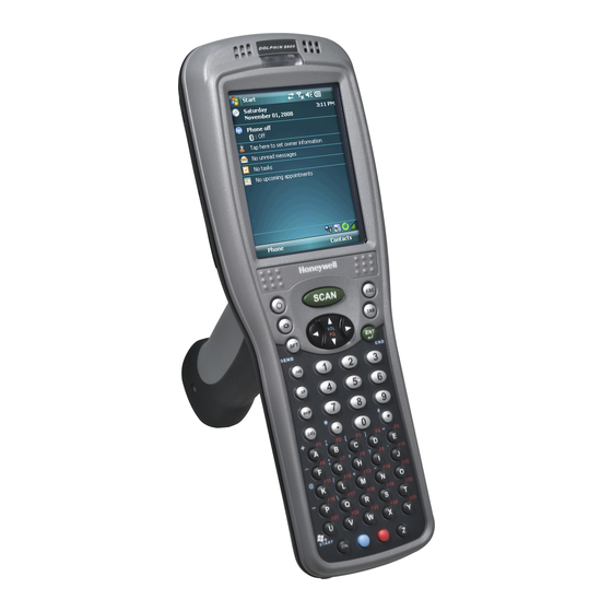
Page 26: Front Panel: 9900, 9950, And 9951
Front Panel: 9900, 9950, and 9951 Indicator LED Front Speaker Touch Panel Display SCAN Key Navigation Keys Recessed Keyboard I/O Connector 3 - 4... -
Page 27: Front Panel Features For The 9900, 9950, And 9951
Front Panel Features for the 9900, 9950, and 9951 Front Speaker The integrated speaker that sounds audio signals as you scan bar code labels and enter data. The operating frequency range is 500Hz at 71 dB up to 80 dB. I/O Connector I/O Connector on page 3-12. -
Page 28: Back Panel: 9900
Back Panel: 9900 Image/Scan Engine Window Rear Speaker IrDA Port Stylus Slot Fastener for the Stylus Tether Fastener for the Stylus Tether Battery Well Microphone For a description of each callout, see Back Panel Features for the 9900, 9950, and 9951 on page 3-9. -
Page 29: Back And Side Panels: 9950 And 9951
Back and Side Panels: 9950 and 9951 The back panel of the 9950 and 9951 contains an integrated, pistol-grip handle for a more ergonomic grip in scan-intensive applications. The stylus is stored inside the handle for easy access. Side Panel Image/Scan Engine Window Scan Trigger... -
Page 30: Back Panel
Back Panel Image/Scan Engine Window Rear Speaker Pistol-Grip Handle Battery Well For a description of each callout, see Back Panel Features for the 9900, 9950, and 9951 on page 3-9. 3 - 8... -
Page 31: Back Panel Features For The 9900, 9950, And 9951
Back Panel Features for the 9900, 9950, and 9951 Battery Well The Battery Well is a recessed area on the back panel that holds the Li-ion battery pack. For more information, see Batteries on page 3-14. Fastener for the Stylus Tether Stylus tethers can be purchased separately to help you keep the stylus attached to the 9900 when not in the slot to prevent loss. -
Page 32: Side Panels: 9900, 9950, And 9951
Side Panels: 9900, 9950, and 9951 The left and the right side panels contain different features. Left Side Audio Jack (2.5mm) Memory Card Door Memory Card Door This door provides user access to the industry-standard SD memory interface. You can open this door to insert SD memory cards to expand the terminal’s memory capacity. -
Page 33: Installing A Memory Card
Installing a Memory Card 1. Press the Power key to put the terminal in Suspend Mode; see Suspend Mode on page 3-18. 2. Remove the battery. 3. Place the terminal on a flat, secure surface with the keyboard face down. 4. -
Page 34: Bottom Panel: 9900, 9950, And 9951
Bottom Panel: 9900, 9950, and 9951 I/O Connector Note: Signals referenced are for a DTE device. I/O Connector The I/O connector powers the terminal, charges the main battery, and facilitates communication. All Dolphin peripherals are designed to work exclusively with this connector. The I/O connector supports RS-232 and USB communication. -
Page 35: Using The Touch Panel
Honeywell also mandates use of a proper stylus, which is one that has a stylus tip radius of no less than 0.8mm. Use of the Honeywell stylus included with the terminal is recommended at all times. -
Page 36: Healthcare Housing
Both batteries must be completely charged before using a Dolphin terminal for the first time! Main Battery Pack We recommend use of Honeywell Li-Ion battery packs. Use of any non-Honeywell battery may result in damage not covered by the warranty. -
Page 37: Internal Backup Battery
• Although your battery can be recharged many times, it will eventually be depleted. Replace it after the battery is unable to hold an adequate charge. • If you are not sure the battery or charger is working properly, please send it to Honeywell International or an authorized service center for inspection. -
Page 38: Managing Battery Power
Charging The internal backup battery is powered by the main battery pack. Therefore, charging the internal backup battery requires that the main battery pack be installed in the terminal and the terminal be connected to a charging device. The internal backup battery must be fully charged before using the terminal for the first time. The initial charge cycle takes approximately 8 hours. -
Page 39: Checking Battery Power
Setting Critical and Low Battery Points Developers can reset the battery parameters in the registry from 0 (no warning) to 99 (would nearly always warn). You can review and set these battery points in the RegEdit Power Tool. 1. Tap Start > Power Tools > RegEdit. 2. -
Page 40: Resetting The Terminal
Resetting the Terminal There are two types of system resets: a soft and a hard reset. Soft Reset (Warm Boot) A soft reset re-boots the device without losing RAM data. You would perform a soft reset when • the terminal fails to respond. •... -
Page 41: Chapter 4 - Using The Scan Image Engine
Using the Scan Image Engine Overview The Dolphin terminal houses a compact image engine that instantly reads popular 1D and 2D bar codes and supports omni-directional aiming and decoding for greater flexibility in real-world settings. The image engine can also capture digital images, such as signatures and pictures of damaged inventory. With the latest CMOS-based technology, the engine works like a digital camera and enables digital image capture, signature capture, and reading of OCR characters. -
Page 42: Available Laser Engines
Available Laser Engines High Performance (HP) 5 mil 55 mil reflective Working Range: Near 2.75 in 5 in (0.07 m) (0.13 m) 7 in 66 in (0.17 m) (1.7 m) Long Range (LR) 10 mil 100 mil reflective Working Range: Near 11 in 60 in... -
Page 43: Supported Bar Code Symbologies
Supported Bar Code Symbologies Symbology Type Symbology Name 1D Symbologies Codabar ISBT 128 Code 3 of 9 Matrix 2 of 5 Code 11 Code 32 Pharmaceutical (PARAF) Plessey Code 93 PosiCode Code 128 Straight 2 of 5 IATA EAN with Add-On Straight 2 of 5 Industrial EAN with Extended Coupon Code Telepen... -
Page 44: Decoding
Decoding The terminal supports two types of image decoding for use in various bar code reading and imaging applications: full-area imaging and Advanced Linear Decoding (ALD). Full-Area Imaging Full-area imaging provides omni-directional reading of linear and non-linear 1D and 2D bar codes, OCR, signature capture, and picture taking. -
Page 45: Aiming Options
Aiming Options The aiming beams are smaller when the terminal is held closer to the code and larger when it is farther from the code. Symbologies with smaller bars or elements (mil size) should be read closer to the unit whereas symbologies with larger bars or elements (mil size) should be read farther from the unit. -
Page 46: Capturing Images
Capturing Images The image-capture process is an intuitive, split-second operation for experienced users. By following the basic guidelines, new users can easily develop their own technique and, with practice, quickly learn to adapt it to different application environments. Image Preview When the imaging process is initiated, the touch screen displays a preview of the object. -
Page 47: Uploading Images
Enabling the Aimer If your Dolphin terminal is configured with the 5300 imager, you can enable the aiming pattern for imaging in the Imaging Demo. For details about the aimer, see 5300 Red High-Vis Aiming Pattern on page 4-5. 1. Tap Start > Demos > Imaging Demo > Setup menu > Aimer. 2. - Page 48 4 - 8...
-
Page 49: Chapter 5 - Using The Keyboards
Using the Keyboards Available Keyboards There are three keyboard options in the 9900 series: SCAN SCAN SCAN E NT E NT S E N D S E N D E N D E N D SEN D EN D BKSP WXYZ PQRS I N S... -
Page 50: Common Buttons
Common Buttons Using the Function Keys on page 5-2. Using the Modifier Keys on page 5-3. Using the Navigation Keys on page 5-3. Using the Function Keys Name Function Backlight Turns the keyboard backlight on and off. Backspace Moves the cursor back one space each time the key is pressed. If you are BKSP typing text, it deletes the previous character each time it is pressed. -
Page 51: Using The Modifier Keys
Using the Modifier Keys Name Function Shift The SFT key modifies only the next key pressed; it must be pressed before each key you wish to modify. SFT toggles the keyboard between uppercase alphabet mode and lowercase alphabet mode. Double-tap SFT to toggle Caps Lock on and off. When Caps Lock is toggled on, characters are uppercase;... -
Page 52: Sticky Key Functionality
Sticky Key Functionality Sticky key functionality is supported for the CTRL key, which means that you don’t have to press and hold the CTRL key when you press the next key. Instead, just tap CTRL and then the next key. You need to open RegEdit and enable the \HKEY_LOCAL_MACHINE\HARDWARE\DEVICEMAP\KEYBD key. -
Page 53: 35-Key Alpha/Numeric Keyboard
35-Key Alpha/Numeric Keyboard SCAN Key Navigation Keys Power Key Escape Key SCAN Backlight Key Tab Key Shift Key Enter Key SEND WXYZ PQRS Space Key Backspace Key Delete Key Alpha Key STA RT CTRL Blue ALT Modifier Keys ALPHA Key The ALPHA key enables you to toggle between the alpha and numeric modes. -
Page 54: 35-Key Keyboard Combinations
35-Key Keyboard Combinations Shift-NUM Alpha Shift-Alpha BLUE Power Suspend/Resume Scan Scan Scan Scan Scan Escape Escape Escape Escape Backlight Toggles Keyboard Backlight On/Off SHIFT Shift Shift Send (phone call) ENTER Enter Enter Enter Enter End (phone call) Left Left Left Left Left Volume Up... - Page 55 Shift-NUM Alpha Shift-Alpha BLUE BKSP Backspace Backspace Backspace Backspace Delete Delete Delete Delete Delete Insert CTRL Control Control Blue Blue Blue Menu Menu 5 - 7...
-
Page 56: 43-Key Alpha/Numeric Keyboard
43-Key Alpha/Numeric Keyboard SCAN Key Navigation Keys Power Key Escape Key SCAN Backlight Key Tab Key Enter Key NUM Lock Key SEND NUM Lock Pad NUM Lock Indicators ‘ Space Key Backspace Key START START BKSP CTRL CTRL Blue Modifier Keys Number Lock (NUM) Key The Number Lock key enables you to toggle between the alpha and numeric modes. -
Page 57: 43-Key Keyboard Combinations
43-Key Keyboard Combinations Alpha Alpha Shift NUM Lock NUM Shift BLUE - (subtract) _ (underscore) & = (equals) . (period) > , (comma) < + (plus) ; (semi-colon) : (colon) ‘ (apostrophe) / (forward slash) \ (backslash) Start menu Space Space Space Insert... - Page 58 43-Key Keyboard Combinations Alpha Alpha Shift NUM Lock NUM Shift BLUE Down arrow Down Down Down Volume down Page down Shift Shift Shift Send (a phone call) Enter Enter Enter End (a phone call) 5 - 10...
-
Page 59: 56-Key Full Alpha/Numeric Keyboard
56-Key Full Alpha/Numeric Keyboard SCAN key Navigation keys Power key Escape key SCAN Backlight key Tab key Shift key Enter key SEND Insert key Space key Backspace key BKSP Delete key START CTRL CTRL Blue Red Modifier keys 5 - 11... -
Page 60: 56-Key Keyboard Combinations
56-Key Keyboard Combinations SHIFT BLUE & , (comma) < # (pound) . (period) > * (asterisk) + (plus) ; (semi-colon) [ (left bracket) ] (right bracket) " (quotes) - (minus) : (colon) ‘ (apostrophe) ? (question mark) ` (accent) / (forward slash) = (equal sign) ~ (tilde) _ (underscore) - Page 61 56-Key Keyboard Combinations SHIFT BLUE Start menu Up arrow Volume up Page up Down arrow Volume down Page down Send (a phone call) End (a phone call) Blue Toggle CAPSLOCK 5 - 13...
-
Page 62: General Windows Keyboard Shortcuts
General Windows Keyboard Shortcuts Press these keys, To… CTRL + C Copy CTRL + X CTRL + V Paste CTRL + Z Undo DELETE Delete CTRL + Right Arrow Move the insertion point to the beginning of the next word. CTRL + Left Arrow Move the insertion point to the beginning of the previous word. -
Page 63: Chapter 6 - System Settings
System Settings Overview Customized settings are available on the Start menu. Tap Start > Settings and the settings screen opens displaying the Personal tab. Settings consists of three tabs: Personal, System, and Connections. Personal Tab System Tab Connections Tab Description See Page Personal Customizes buttons, set SIP options, and... -
Page 64: Personal Tab
Personal Tab To access the Personal tab, go to Start > Settings. The screen opens displaying the Personal tab. Icon Description See Page Buttons Program the side buttons to perform specific Buttons on page 6-3. tasks. Input Customizes the SIP (soft input panel). Input on page 6-4. -
Page 65: Buttons
Buttons The Buttons setting programs certain keyboard buttons to launch applications or execute commands. Enable HotKeys Default Buttons setting assignments inactive until you enable the HotKeys Power Tool. Tap Start > Power Tools and tap the HotKeys icon once . HotKeys is enabled, and the button assignments in the Buttons setting are active. -
Page 66: Input
Command Description <None> Nothing happens when the button is pressed. <OK/Close> Performs the same function as tapping OK on the screen. <Scroll Down> Scrolls down in the open application. <Scroll Left> Scrolls left in the open application. <Scroll Right> Scrolls right in the open application. <Scroll Up>... -
Page 67: Menus
Menus You can add existing programs you use often, such as File Explorer, to the Start menu for faster access. You are not installing the program, just allowing access to it from the Start menu. To add programs to the Start menu, you can use •... - Page 68 2. Tap and hold on the program, then tap Copy on the pop-up menu. 3. Navigate to the Windows folder and open the Start Menu (My Device > Windows > Start Menu), tap and hold a blank area of the window, and tap Paste Shortcut on the pop-up menu. 4.
-
Page 69: System Tab
System Tab The System tab enables you to verify and sometimes alter system parameters. To access the System tab, go to Start > Settings > System tab. Tap the appropriate icon to open that system setting. Icon See Page About About on page 6-8. -
Page 70: About
About The About system setting displays specific information about the terminal. It contains three tabs: Version Tab Displays the information about the software, operating system, and processor. Device ID Tab Displays the information the terminal uses to identify itself to other devices. It can be important to know this information if the Dolphin terminal is going to be part of a networked system of devices. -
Page 71: Certificates
Certificates The Certificates option shows you the certificates recognized by the operating system. ClearType Tuner This system setting enables you to adjust the level ClearType font rendering by moving a slider. The sample text displays the setting results immediately. Of course, you must first enable ClearType font rendering to change the appearance of fonts on the screen;... -
Page 72: Encryption
Encryption Encryption gives you the option of encrypting files placed on storage cards so that those files cannot be read by any other device. Error Reporting Error Reporting gives you the option of enabling or disabling the error reporting function of Windows Mobile 6.1. -
Page 73: Memory
You cannot change the terminal’s memory allocation in the Memory system setting. To change the memory allocation, you need to use the SetRAM Power Tool (Start > Power Tools > SetRAM). For more details, please refer to the Honeywell Power Tools User’s Guide, which is available for download from www.honeywellaidc.com. -
Page 74: Power
Running Programs Tab Displays the software programs currently using Storage memory. Check this tab when you are receiving out of memory errors or when the mobile computer is running slowly. You can • Select a program in the list and tap Stop to stop it from running (and therefore from using memory), or •... -
Page 75: Regional Settings
Regional Settings Regional Settings enables you to customize the appearance and formatting to your geographic region. Specifically, you can customize numbers (i.e., number of decimal places allowed), currency (i.e.,using the $ or € € symbol), time, and date. These specifications apply to all screens, including the Today screen. The Region tab displays an overview of the region selected in the drop-down list at the top. - Page 76 Screen The Screen system setting contains three tabs: Alignment, Clear Type, and Text Size. Alignment Tab You need to re-align the screen if tapping buttons or icons with the stylus no longer seems to work appropriately. Tapping Align Screen brings up the align screen window where you are guided to tap a target several times.
-
Page 77: Wan Info
WAN Info When the GSM radio is active, WAN Info displays useful statistics for the radio. To verify whether or not the GSM radio is enabled, check the Dolphin Wireless Manager (see page 7-6). Windows Update Windows Update is designed to download Microsoft updates to the operating system directly from Microsoft. - Page 78 6 - 16...
-
Page 79: Chapter 7 - Communication
Enables you to configure Wireless Zero Config (WZC). This icon appears only if the 802.11b/g driver is loaded on the terminal and the Honeywell WLAN Security Supplicant is not loaded. By default, the Wireless Zero Config is disabled and the supplicant is loaded. -
Page 80: Using The Irda Port
Using the IrDA Port Using the IrDA port, you can send and receive data between the terminal and other devices equipped with infrared. This can include, but is not limited to, Windows Mobile information such as Contacts and Tasks, as well as software upgrades. The maximum data transfer speed is 115 Kbps. -
Page 81: Receiving Data
5. When the IrDA port finds the aligned IrDA port, it immediately starts sending the selected file. The selected device reads “Sending.” 6. When the file transfer is complete, the selected device reads “Done.” Receiving Data The Beam Setting must be set to receive for the terminal to receive data from other infrared devices. 1. -
Page 82: Connections Manager
Connections Manager Microsoft’s connection manager sets up multiple network connections to Internet Service Providers (ISPs) via an external modem. Do NOT enter connection parameters in the Connections Manager if: • You are using one of the on-board wireless radios to connect to a network. The Dolphin terminal uses the settings from each radio’s configuration utility to connect. -
Page 83: Advanced Tab
*Proxy Server Connections If you are connected to your ISP or private network during synchronization, the terminal should download the proper proxy settings during synchronization with the PC. If these settings are not on your PC or need to be changed, ask your ISP or network administrator for the proxy sever name, server type, port, type of Socks protocol used, and your user name and password. -
Page 84: Dolphin Wireless Manager
Dolphin Wireless Manager The Dolphin Wireless Manager provides a centralized interface that enables and disables all the on-board radios. Each radio has its own configuration program. The Dolphin Wireless Manager also provides shortcuts to the configuration utilities for each radio. Dolphin Wireless Manager Window Tap Start >... -
Page 85: Accessing Radio Configuration Utilities
There are three radio configuration utilities: For 802.11b/g: Tap WLAN Settings and the Honeywell WLAN Security Supplicant opens. The Honeywell WLAN Security Supplicant User’s Guide is available for download from the Dolphin 9900 product page at www.honeywellaidc.com. For Bluetooth: Tap Bluetooth Settings and the Bluetooth Settings open. -
Page 86: Activesync Communication
When communicating via ActiveSync, your terminal is designed to be connected to the host workstation with a communication peripheral sold/manufactured by Honeywell, such as the charge/communication cable. Use of any peripheral not sold/manufactured by Honeywell may cause damage not covered by the warranty. Capabilities •... -
Page 87: Communicating With The Dolphin Terminal
Setting Up the Host Workstation Verify that ActiveSync is configured to use the appropriate communication type by clicking File > Connection Settings. For RS-232 communication, For USB communication, check Allow USB connections. connect to COM1. Note: You can have both USB and RS-232 selected in the software without affecting processing. However, your hardware setup should use only RS-232 or USB, not both. -
Page 88: Installing Additional Software
2. Read any installation instructions, Read Me files, or documentation that comes with the program. Many programs provide special installation instructions. 3. Connect the terminal to the desktop computer via a Honeywell communication peripheral. If the File is an Installer: An installer program is one that installs on the PC and the terminal simultaneously;... -
Page 89: Adding Programs Directly From The Internet
3. Depending on the program, you may need to open File Explorer on the terminal, navigate to the folder where the program is located, and tap on the program file to install it. • If you copied the file to the Autoinstall folder, you can either tap on the program inside the Autoinstall folder or perform a hard reset and the program will install as part of the Autoinstall process that occurs during each hard reset. -
Page 90: 9900/9950/9951 Com Port Assignment Table
9900/9950/9951 COM Port Assignment Table COM Port Description COM0 Unused COM1 Serial Port: RS-232 Connector on the bottom panel COM2 Not accessible COM3 IrDA: Serial Infrared (SIR) up to 115 Kbps COM4 Not accessible COM5 Bluetooth DUN COM6 IrCOMM COM7 GPS: COM Port for the GPS receiver COM8 USB Serial: Virtual USB Serial port for ActiveSync... -
Page 91: Chapter 8 - Working With Gsm
Working with GSM Overview The Dolphin 9900 terminal can be configured with an integrated, embedded GSM/GPRS quad-band radio module for WWAN communication. Short for Global System for Mobile communications, GSM is an open, non-proprietary wireless WAN system that is constantly evolving and growing. -
Page 92: Sim Card Installation
3. Unscrew the faceplate of the SIM card door. You must use a Torx T6 wrench. You can purchase this wrench from Honeywell, part number 100001700. 4. Insert your SIM card. Make sure the interface on the card is connected to the SIM Card interface in the slot;... - Page 93 5. Place the SIM card door over the secured SIM card and fasten the screws. Screws SIM Card Door SIM Card SIM Card Interface 6. Install the battery pack and turn on the terminal. 8 - 3...
-
Page 94: Enabling The Gsm Radio
Enabling the GSM Radio Be default, the GSM radio should be enabled after each hard reset. Verify the status of the radio in the Dolphin Wireless Manager. Tap Start > Settings > Connections tab > Dolphin Wireless Manager If the Phone is set to OFF, tap the Phone rectangle and the GSM radio enables. 8 - 4... -
Page 95: Voice Communication
Voice Communication You can use the Dolphin terminal as a phone over the GSM radio. Audio Modes The back panel of the 9900, 9950, and 9951 contains both a speaker and a microphone that you can use to send and receive audio signals over the GSM network; see Back Panel: 9900 on page 3-6. -
Page 96: Sending Calls
Sending Calls After the number is dialed, tap Talk or use the keyboard. Note: The icon indicated that the phone is in use. Ending Calls While the phone call is live, tap End or use the physical keyboard. Keyboard Combinations for Calls Keyboard To Send a Call, Press…... -
Page 97: Setup Options
Setup Options Tap Menu > Options. The Phone Settings tab windows appear. Phone Tab Services Tab Network Tab Establish or change a PIN on the For each service, the phone will read You can set networks on the Network Phone tab. settings from the network on the SIM tab. -
Page 98: Data Communication
Data Communication You set up data communication via the connections manager. The carrier on the SIM card is the ISP. System Requirements • The GSM radio must be enabled; see Enabling the GSM Radio on page 8-4. • You must have an active SIM card installed; see SIM Card Installation on page 8-2. - Page 99 4. Enter the APN and tap Next. 5. Enter the username and password from the account and tap Finish. 6. On the Connections window, tap Manage existing connections. The connection you just created should appear in the list on the modem tab. 8 - 9...
-
Page 100: Ending The Data Connection
7. Tap and hold on the connection and select Connect on the popup menu. 8. The network icon in the navigation bar indicates the GSM radio is attempting to connect 9. When the connection is complete, the network icon changes to: 10. -
Page 101: Roaming
Roaming You can select automatic or manual roaming. The Phone defaults to automatic roaming. 1. When an active SIM card is inserted in the terminal, tap Start > Settings > Personal tab > Phone . The Phone Settings window appears. 2. - Page 102 8 - 12...
-
Page 103: Chapter 9 - Working With The Bluetooth Radio
Working with the Bluetooth Radio Enabling the Bluetooth Radio You enable the Bluetooth radio in the Dolphin Wireless Manager (see page 7-6). 1. Tap Start > Settings > Connections tab > Dolphin Wireless Manager 2. Tap anywhere inside the Bluetooth rectangle and Bluetooth begins activating. 3. -
Page 104: Connecting To Other Bluetooth Devices
Connecting to Other Devices Bluetooth You need to perform a device discovery and then select a discovered device and connect to it. Pairing happens as part of the connection process. 1. In the Dolphin Wireless Manager, tap Menu > Bluetooth Settings. Tap Start >... - Page 105 4. You are prompted to enter a passcode. If the device has a specific passcode, enter it in the Passcode field and tap Next. If the device does not have a specific passcode, enter one in the Passcode field and tap Next. The Bluetooth radio tries to connect with the device.
-
Page 106: Pairing And Trusted Devices
8. The device appears in the list on the main window. 9. After the passcodes have been accepted on both sides, you have a trusted (“paired”) connection. Pairing and Trusted Devices The terminal does support pairing. Pairing happens during general connection setup. Paired devices are "trusted"... -
Page 107: Types Of Devices And Services
Types of Devices and Services When you tap Add new device on the Devices tab, the Bluetooth radio scans for discoverable Bluetooth devices in range, which are Bluetooth devices that have been made discoverable. Device Types The types of devices in the vicinity of the radio appear in the list of discovered devices. -
Page 108: Connecting To Bluetooth Printers
Connecting to Bluetooth Printers 1. Make sure the Bluetooth printer is in range and set to be discoverable by other Bluetooth devices. 2. Look up the Bluetooth printer’s broadcasted ID. 3. Perform a device discovery (Tap Settings > Connections > Bluetooth > Add new device.) 4. -
Page 109: Transferring Files
Transferring Files 1. Tap Start > Programs > File Explorer. 2. Navigate to the file you want to transfer. 3. Tap and hold on the file and select Beam File on the popup menu. 4. The Bluetooth radio begins searching for devices. When a Bluetooth device is first found, it appears as an Unknown device;... -
Page 110: Making The Terminal Discoverable
Making the Terminal Discoverable By default, the Dolphin terminal is not discoverable, which means that the terminal will not be found by other Bluetooth devices. To make the terminal discoverable, tap the Mode tab. Select Make this device visible to other devices and tap OK. Selecting COM Ports You can select COM ports 0-9. -
Page 111: Chapter 10 - Working With Gps
Working with GPS Overview The Dolphin 9900 terminal contains an integrated GPS module that allows location tracking of workers and vehicles, providing better utilization of field assets. Optional mapping and navigation software provides turn-by-turn driving directions and location information, allowing workers to arrive on time. -
Page 112: Com7
COM7 COM Port 7 can be set to the following baud rates: • 4800 • 9600 (This is the default baud rate and recommended for optimal GPS functioning.) • 19200 • 38400 Other baud rates are not possible. The baud rate selected on COM7 is the actual baud rate with which the GPS will be communicating. -
Page 113: Chapter 11 - Dolphin Homebase Device
This means that one base can charge two battery packs: the one installed in the terminal and a spare. We recommend use of Honeywell Li-Ion battery packs. Use of any non-Honeywell battery may result in damage not covered by the warranty. -
Page 114: Parts And Functions
Parts and Functions Front Panel Terminal Well Auxiliary Battery Well DOCK LED Battery COMM LED Terminal Well Place the terminal in this well to communicate with a host device, power the terminal, and charge its battery pack. If the host device is a workstation that uses ActiveSync, synchronization begins immediately. - Page 115 COMM LED This is the communication LED. It indicates the status of data transfer between the Dolphin terminal and the host device. The color of this LED differs if the base is using the serial or USB port connection. If using the serial port This color means…...
-
Page 116: Power
The terminal requires 9.5 Volts DC input for communications and battery charging; the power adapter on the power cable converts the voltage from the power source to 9.5 volts DC. Only the Honeywell 9.5 VDC 4A power supply provided with the base converts the voltage appropriately. -
Page 117: Serial Connector
Serial Connector The following diagram displays the pin diagram of the serial connector of the base. Note: Signals referenced are for a DTE device. The base is at a right-angle to the printed circuit board (PCB). The ninth pin has a ring indicator (RI). 11 - 5... -
Page 118: Charging The Main Battery
Country on page 1-3.). Replace only with battery pack type 200002586 manufactured by Honeywell International Incorporated. Warning: Explosion Hazard. Charge or replace the battery only in an area known to be non-hazardous. Warning: Explosion Hazard. Do not replace components unless power has been switched off or the area is known to be non-hazardous. -
Page 119: Communication
2. Snap the battery into place with a hinging motion. The Aux Battery LED lights orange. 3. Use the AUX Battery LED to monitor charging progress. Communication Dolphin terminals support USB communications out of the box. The base also supports USB communications via the USB port located on the back. The base acts as a USB device by interfacing the USB signals of the Dolphin terminal to the USB of the host workstation. -
Page 120: Verifying Data Transfer
• The Dolphin terminal activates; if the power is off, the terminal automatically powers on. If the terminal does not power on, verify that the Honeywell power supply is properly connected to the cradle and plugged into a functioning outlet. -
Page 121: Rs-232 Pin Configuration
RS-232 Pin Configuration Base /Host Port IBM AT DB9 IBM XT DB25 Modem DB25 (DCE) (DTE) (DTE) (DCE) Pin / Input Signal 2 / (RD) 3 / (TD) 5 / (SG) 4 / (DTR) 6 / (DSR) 7 / (RTS) 8 / (CTS) Note: This base cannot be daisy-chained. -
Page 122: Desk Mounting
Desk Mounting The DIN rail slot (7.5 X 35 mm) may be mounted on the bottom to allow for secure desk attachment of the unit if desired. Serial and USB port location (not in view) Auxiliary Battery Well DIN Rail (7.5 X 35 mm) Slide the DIN rail slot along the bottom panel. - Page 123 For any of the screws positioned so that they are going directly into dry wall, use a sheet rock anchor/ screw set such as the one listed below. For any of the screws attaching directly into concrete, drill the appropriately sized pilot hole into the concrete and secure the bracket to the wall using concrete anchor screws such as those listed below.
- Page 124 11 - 12...
-
Page 125: Chapter 12 - Dolphin Mobile Base Device
Intelligent battery charging makes the base a safe and convenient storage receptacle for your Dolphin terminal. We recommend use of Honeywell Li-Ion battery packs. Use of any non-Honeywell battery may result in damage not covered by the warranty. We recommend use of Honeywell peripherals, power cables, and power adapters. Use of any non-Honeywell peripherals, cables, or power adapters may cause damage not covered by the warranty. -
Page 126: Front Panel
Front Panel The following graphic features the base with a terminal inserted into the terminal well: Terminal Well Mounting Bracket DOCK LED COMM LED Terminal Well Place the terminal in this well. Once seated, the terminal can communicate with a host device and its main battery pack begins charging. -
Page 127: Bottom Panel
Bottom Panel The power supply and RS-232 connectors are located on the bottom of the unit. RS-232 Communications Port Power Supply Connector Power Supply Connector Attach the power cable that came with the base to this connector. The base can be powered by an external DC power source of between 11 VDC to 48 VDC. -
Page 128: Charging The Dolphin Terminal
Charging the Dolphin Terminal The base supplies charging power to the Dolphin terminal so that the terminal can monitor the charging of its battery pack. This charging method protects the battery from being damaged by overcharging. Therefore, the Dolphin terminal may be stored indefinitely in the base without damage to the terminal, the battery pack, or the base. -
Page 129: Power
The disk contains drill holes you use to secure the base to the mounting surface. Power Note: Honeywell recommends that you leave the base connected to its power source at all times. The base is powered via the power connector on the bottom panel; see Bottom Panel on page 12-3. -
Page 130: Establishing Communication
Establishing Communication The RS-232 interface allows the terminal to communicate to a workstation, modem, or any standard RS- 232 device using a standard serial cable and communications software. Requirements You need the following equipment: • A Mobile Base device powered by a power cable and power adapter cable •... - Page 131 RS-232 Pin Configuration Base/Host Port (DCE) IBM AT DB9 IBM XT DB25 Modem DB25 (DTE) (DTE) (DCE) Pin / Input Signal 2 / (RD) 3 / (TD) 5 / (SG) 4 / (DTR) 6 / (DSR) 7 / (RTS) 8 / (CTS) Refer to this table if you want to make your own cables.
- Page 132 Serial Connector The base connector is straight to the printed circuit board (PCB). The ninth pin sends 500mA at 5V power out. This can power a peripheral device, such as a mobile printer, as long as that peripheral device can accept 500mA at 5V.
-
Page 133: Chapter 13 - Dolphin Chargebase Device
The base can hold up to 4 Dolphin terminals. Each charging slot charges each terminal independently of the other slots. We recommend use of Honeywell Li-Ion battery packs. Use of any non-Honeywell battery may result in damage not covered by the warranty. -
Page 134: Parts And Functions
Parts and Functions Front Panel Terminal Wells Dock Charge Terminal Wells The base contains 4 terminals wells. Each well • Holds and charges the main battery pack of one Dolphin terminal. • Contains the companion to the I/O connector on the bottom panel of Dolphin terminals. •... -
Page 135: Supplying Power
Power Supply The base includes a power supply that contains a power adapter to ensure the proper voltage. The power adapter is plugged into standard AC/DC outlets. Supplying Power 1. Be sure the power switch on the power adapter is in the OFF position. 2. -
Page 136: Inserting And Removing Terminals
Inserting and Removing Terminals 1. Slide the terminal into the well until the Dock LED lights solid green. 2. Charging begins immediately. Note: To remove a terminal, grasp it firmly in your hand and lift it up and out of the terminal well. The LEDs for the terminal well turn off. -
Page 137: Mounting
Mounting This base should be mounted to a dry, stable surface. When choosing a location, always bear in mind that • The mounting location must allow users easy access to the power connector. • The base should be oriented so that users can easily read the labels. Bottom Panel The bottom panel offers two mounting options: insert a DIN Rail for desk mounting or use mounting brackets with the available screw slots for wall mounting. - Page 138 Desk Mounting The DIN Rail (7.5 X 35 mm) slot on the bottom panel enables secure mounting. Installation Hardware Screw: 3/16 in. dia x 5/8 in. long pan head screw Washer: 1/2 in. OD x 7/32 in. ID x 3/64 in. thick Nut: 3/16 in.
- Page 139 Wall Mounting You need to purchase two wall mount kits that each contain: • a mounting bracket, • three screws, and • six washer/nut sets. You need two kits so that you have two mounting brackets–one for each end of the device–and enough screws (4) and washer/nut sets (8).
- Page 140 13 - 8...
-
Page 141: Chapter 14 - Dolphin Quadcharger Device
(CC-CV) that is recommended for Li-ion batteries. The process monitors changes in temperature, current, and voltage and resets the battery pack. We recommend use of Honeywell Li-Ion battery packs. Use of any non-Honeywell battery may result in damage not covered by the warranty. -
Page 142: Parts And Functions
Parts and Functions Top Panel Status LED Battery Capacity LEDs Analyze Button Charging Slots Charge/Analyze Slot Charging Slots There are 4 charging slots. Each slot holds one Li-ion battery and charges it independently of the other slots. When a battery is placed in each slot, it immediately begins charging. Charge/Analyze Slot This is the 4th slot and the only one that can be used to analyze a battery. -
Page 143: Supplying Power
90-265 volts. Supplying Power The charger must be connected to a power source via the Honeywell power adapter cable so that voltage is adjusted appropriately. 1. Locate the AC power adapter cable and plug it into the power source. -
Page 144: Inserting And Removing Battery Packs
Inserting and Removing Battery Packs To insert a battery pack, place the end of the battery without the locking tab into the bottom of the charging pocket and snap the battery into place with a hinging motion. The Status LED for that particular slot illuminates orange when the battery has been properly inserted. -
Page 145: Using The Battery Analyzer
Using the Battery Analyzer Purpose Using the Charge/Analyze slot helps you monitor the charge capacity of Li-ion batteries over time. Location The battery analyzer is located in the 4th slot - named the Charge/Analyze slot - of the ChargeBase. Only a battery placed in this slot can be run through an Analyze cycle. -
Page 146: Mounting
Mounting The charger should be on a dry, stable surface and can be mounted on a flat, horizontal surface such as a desktop or workbench, or a flat, vertical surface such as a wall. When choosing a location, always bear in mind that •... -
Page 147: Wall Mounting
Wall Mounting Use the appropriate nuts and bolts listed above to secure the DIN rail to a wall. 14 - 7... -
Page 148: Troubleshooting
The Status LED lights red and stays on An error occurred during the self-diagnostic test for that without a battery in the charging slot. particular charging pocket. Call Honeywell Product Service and request an RMA. For additional warranty and return information, see... -
Page 149: Chapter 15 - Customer Support
Customer Support Product Service and Repair Honeywell International Inc. provides service for all its products through service centers throughout the world. To obtain warranty or non-warranty service, contact the appropriate location below to obtain a Return Material Authorization number (RMA #) before returning the product. -
Page 150: Technical Assistance
For ongoing and future product quality improvement initiatives, 9900s, 9950s, and 9951s comes equipped with an embedded device lifetime counter function. Honeywell may use lifetime counter data for future statistical reliability analysis as well as ongoing quality, repair and service purposes. -
Page 151: Limited Warranty
• The duration of the limited warranty for batteries is one year. Use of any battery from a source other than Honeywell may result in damage not covered by the warranty. Batteries returned to Honeywell International Inc. in a reduced state may or not be replaced under this warranty. -
Page 152: How To Extend Your Warranty
How to Extend Your Warranty Honeywell International Inc. offers a variety of service plans on our hardware products. These agreements offer continued coverage for your equipment after the initial warranty expires. For more information, contact your Sales Representative, Customer Account Representative, or Product Service Marketing Manager from Honeywell International Inc., or your Authorized Reseller. - Page 154 Honeywell Scanning & Mobility 9680 Old Bailes Road Fort Mill, SC 29707 www.honeywellaidc.com ™ 99-UG Rev F 8/10...