
Related Manuals for Gemini GEM-P801


Summary of Contents for Gemini GEM-P801
-
Page 1: Installation Instructions
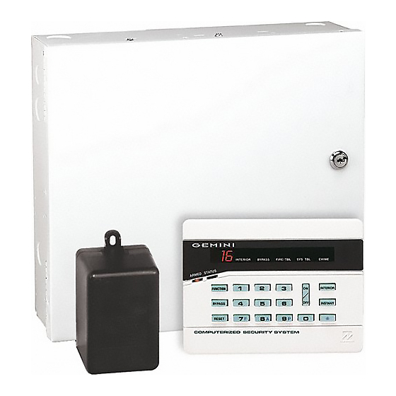
® GEM-P801 Control Panel/Communicator Installation Instructions © NAPCO 2000 WI1089 09/01... -
Page 2: Table Of Contents
Listings and Approvals........4 User 8 code as an Ambush code. Ordering Information ......... 4 Wireless Ready The GEM-P801 is wireless ready. When used with a Optional Accessories ........4 Bell Supervision GEM-RECV-XP8 receiver, the control panel can Programming the Panel ........5... -
Page 3: Specifications
(28 x 30.8 x 7.6) HxWxD Required Transformer: -------------------- NAPCO TRF12 OR BASLER 16.5 VAC 20VA Shipping Weight: --------------------------- GEM-P801 5.5 lbs. Required Battery: --------------------------- 12V 4 AH or 7 AH Rechargeable Operating Temperature: ------------------- 0-49ºC (32-120°F) Change Battery every 5 years or as required Maximum Charging Current: ------------- 165 mA Maximum Input Current: ------------------- 2.58 A... -
Page 4: Ul Compatible Smoke Detectors
WI1089 GEM-P801 Installation Instructions UL Compatible Smoke Detectors Ordering Information GEM-P801 Compatible Smoke Detectors (Approved by UL) GEM-P801 8 zone Control Panel with 2-wire Fire (6 Hardwire/Wireless+2 wireless) 4-Wire 2-Wire Smoke Detector GEM-RP8 Keypad Smoke Detector Smoke Detector Base OI219... -
Page 5: Programming The Panel
3. TELCO JACK attempting to report. 3. Connect terminal 19 (PGM) to terminal 3. RJ31X 4. Apply power to the GEM-P801 control panel. 5. After a few seconds the ARMED, READY and TELCO SYSTEM TROUBLE LEDs will flash. JACK 6. -
Page 6: Installation
WI1089 GEM-P801 Installation Instructions those required, such as the dining room, Installation Wiring bedrooms and utility room. Heat detectors, rather than smoke detectors, are recommended Mounting the Panel Grounding the Panel in kitchens, attics, and garages due to Mount the Panel close to an unswitched AC... -
Page 7: Keypad Operation
Burglary Zone Wiring Fire Zone Wiring Keypad Sounder Wire the Fire Zone as shown in the Wiring The GEM-P801 provides 6 true hard-wired, End- Diagram in the back of this manual. An EOL QUICK BEEPS Of-Line Resistor terminated burglary zones. Wire... -
Page 8: Panel Operation
WI1089 GEM-P801 Installation Instructions protected press the key. Press and hold the Keypad LEDs Panel Operation key for 1.5s to fully set the system Arming (System ON) ARMED LED DEFINITION (The LED on the Keyfob indicate the Keyfob has Before arming the system close all protected... -
Page 9: Bypassing
keypad will beep 6 times, indicating the panel has Zones selected as Home/Away with Delay Press the key then the number of the been disarmed. The red Armed LED will go out. Zones will have a fixed 20-second entry zone to be unbypassed. If an incorrect Arm/Disarm Code is entered, the delay when violated before an Exit/Entry Group Bypass... -
Page 10: User Program Mode
WI1089 GEM-P801 Installation Instructions While in User Program Mode the Armed, Status the load, a low battery indication will be 1. Enter System Trouble LEDs will continue to displayed. A battery test is also performed on 2. Enter User 1 Code ( 1 2 3 4 power-up after a 3 minute delay. -
Page 11: Dealer Commands
While in Fault Find mode, the loop response for Enter this command to turn the keypad sounder Signal Strength = 4 all zones will be set to the faster response of 40 ON/OFF. When the keypad is in Sleep mode all Signal Strength = 5 ms. -
Page 12: Zone Features
WI1089 GEM-P801 Installation Instructions this type have a three (3) minute power-up Uploading Signal Strength Information [01]Home/Away with Delay Zones delay, and do not display or cause an alarm if Zones that automatically bypass at the from the Log faulted when the system powers up. -
Page 13: System Times
permitted for UL installations. armed, allows a user to leave the premises Test Timer without setting off an immediate alarm. If Test Timer [36-4] is enabled, program the [06]Disable EOL Resistor Exit Delay may be programmed for up to interval, in days, between Test Timer reports. Program this zone type if an End Of Line 255 seconds (4¼... -
Page 14: System Features
WI1089 GEM-P801 Installation Instructions and function entries. (2) Enable Keypad AUX ( indicated at the keypad. The Supervisory timer is programmable from 1-8 hours; 0 Additional Programming required: [22]Miscellaneous Features 1 Select reporting to Telco 1 [36-2] or Telco 3 means supervision. - Page 15 output for 5 seconds using the when the panel is Armed. The PGM output Telephone 1 Programming will flash when the panel has gone into command. This programming option has not [30]Subscriber ID Number alarm. been evaluated by UL. For 4/2 format enter a 4 digit number. If 3/1 *Includes Bell Cut, Fire Trouble, Receiver format is required, enter a 3 digit number, (3) Follow Keypad Sounder - The following...
-
Page 16: Telephone Number 1 Programming
WI1089 GEM-P801 Installation Instructions Receiver Formats: Ademco Slow, Radionics AUX or AMBUSH report ( Fire Restore report. Fast, Silent Knight Fast and Universal High (3) Panic - Program to activate a Panic [39]Opening/Closing Report, Telco 1 Speed. This is a sophisticated data format... -
Page 17: Backup Telephone Programming
less than 4 retries remaining. [44]Dialing Prefix (4) Don't Clear Fail to Communicate [47]Leading Digits Dialing prefix for Telco 1, Telco 2, and Telco Program to prevent a good line cut test from Pager PIN Number - If a PIN number is 3. -
Page 18: Telephone Number 3 Programming
WI1089 GEM-P801 Installation Instructions each time a report is sent. [62]Zone Codes Program Opening and Closing Codes for (2) Reserved Users 1 through 8. The second digit of the [62-1] Restore code - Zones 1 through 8. (3) Reserved report code is the number of the user that... -
Page 19: Wireless
[A2] buttons on the Keyfob are pressed. Up to two receivers can be wired to the is to be mapped to the zone. Additional programming required: GEM-P801. Each wireless transmitter can Keypad Panic ( ) [20-3] Programming Example be mapped to a zone. Only 1 wireless device... - Page 20 WI1089 GEM-P801 Installation Instructions Press the [OFF] button to turn the Bell OFF. [91]Ring Count Program the number of rings before the buttons on the Keyfob are pressed (only if 4 PGM panel will pickup. Ring Method [92-1] the system is programmed exclusively for...
-
Page 21: Downloading
Dealer Code of PCPreset required Fire Trouble can be displayed on the 4567 only if Dealer Code Lockout [96-1] 1. Create the GEM-P801 account to be Fire LED. Fire Trouble is indicated by a has not been programmed. downloaded... - Page 22 WI1089 GEM-P801 Installation Instructions Note: All programming within Programming Blocks [96] & [97] will not change if the panel is defaulted. [98] Number of Re-Dials The Number of re-dial attempts made by the panel before indicating Fail-to- Communicate (System Trouble 1-3).
-
Page 23: System Troubles
Audible System Trouble Indication - For all EXAMPLE LOW BATTERY SYSTEM TROUBLE DISPLAY System Troubles system troubles, except when the only system Use the System Trouble chart on the following Enter to enter System Trouble mode trouble is the loss of AC, the keypad will beep page to determine the specific System once every 10 seconds. - Page 24 WI1089 GEM-P801 Installation Instructions System Troubles Keypad Beeps or Zone LED System Trouble Cause/Action SYSTEM Condition Flashes 1 Beep AC Power Failure This trouble will occur if AC power is not present. Ensure that the transformer is connected to an unswitched power source.
-
Page 25: Troubleshooting
Zones programmed as Exit/Entry 6. The PGM Output Pulses in Alarm. Troubleshooting Followers When the PGM lug of the control panel is 2. Zones programmed for 24 Hour programmed for an Armed indication it also 1. The bell output drops to about 3 volts in Protection. - Page 26 WI1089 GEM-P801 Installation Instructions 8. How do I remove Keypad Sounder on If using internal reed, make sure J1 is 12. No Keypad Chime? Alarm? cut and both Point 1 and Point 2 The keypad sounder is turned off with the The keypad sounder follows the Burg terminals are jumped out.
-
Page 27: Gem-P801 Wiring Diagram
This equipment should be installed in accordance with Chapter 2 of the National Fire GEM-P801 WIRING DIAGRAM Alarm Code, ANSI/NFPA 72-1996 (National Fire Protection Association (REFER TO INSTALLATION INSTRUCTIONS WI1089) Batterymarch Park, Quincy MA 02269). and local codes. Information describing... -
Page 28: Limited Warranty
NAPCO's original selling price of the product, for any loss or date of manufacture. NAPCO will, within said period, at its option, repair or replace any damage, whether direct, indirect, incidental, consequential, or otherwise arising out of any product failing to operate correctly without charge to the original purchaser or user.