Table of Contents
Advertisement
Quick Links
Advertisement
Table of Contents

Related Manuals for RuggedCom RUGGEDBACKBONE RX1501


Summary of Contents for RuggedCom RUGGEDBACKBONE RX1501
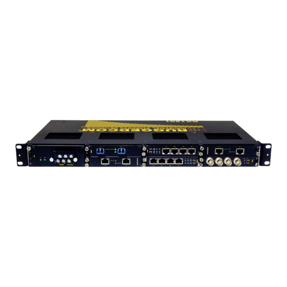
- Page 1 RuggedBackbone™RX1501 v2.4 Installation Guide February 8, 2013 www.RuggedCom.com...
- Page 2 RuggedCom has verified the contents of this manual against the hardware and/or software described. However, deviations between the product and the documentation may exist. RuggedCom shall not be liable for any errors or omissions contained herein or for consequential damages in connection with the furnishing, performance, or use of this material.
-
Page 3: Table Of Contents
RuggedBackbone™RX1501 RuggedBackbone™ RX1501 Installation Guide Table of Contents FCC Statement And Cautions ................Chapter 1 Product Overview ....................1.1 Functional Overview ........................1 1.2 Feature Highlights ........................1 Chapter 2 RuggedBackbone™ Modules ................2.1 Installing a Module ........................5 2.2 Front Panel ..........................5 2.2.1 Module Status LEDs ...................... - Page 4 RuggedBackbone™RX1501 RuggedBackbone™ RX1501 Installation Guide 3.3 Critical Alarm Wiring ........................20 3.4 Serial Console Port ........................21 3.5 WAN Ports: RJ45 ........................21 3.6 WAN Ports: BNC ........................22 3.7 Copper Ethernet Ports ........................ 22 3.7.1 RJ45 Twisted-Pair Copper Ports ..................22 3.7.2 M12 Twisted Pair Copper Ports ..................
-
Page 5: Fcc Statement And Cautions
This product contains no user-serviceable parts. Attempted service by unauthorized personnel shall render all warranties null and void. Changes or modifications not expressly approved by RuggedCom Inc. could invalidate specifications, test results, and agency approvals, and void the user’s authority to operate the equipment. - Page 6 FCC Statement And Cautions RuggedBackbone™ RX1501 Installation Guide...
-
Page 7: Product Overview
RuggedBackbone™ RX1501 Chapter 1 Installation Guide Product Overview Product Overview Section 1.1 Functional Overview The RuggedBackbone™ RX1501 is a cost-efficient, rugged layer 3 switch and router. The RX1501’s modular and field replaceable platform allows you to select WAN, serial, and Ethernet options, making it ideally suited for electric power utilities, the industrial plant floor, and traffic control systems. - Page 8 Chapter 1 RuggedBackbone™ RX1501 Product Overview Installation Guide Physical Ports • Field replaceable line modules • Up to 36 ports 100FX • Up to 36 ports 10/100TX • Up to 8 ports Gigabit Ethernet WAN Port Options • Up to 4 T1/E1 ports via RJ45 connectors (channelized/unchannelized) •...
- Page 9 RuggedBackbone™ RX1501 Chapter 1 Installation Guide Product Overview • Input voltage ranges: 10-36VDC, 36-72VDC, 88-300VDC, 85-264VAC • TUV/UL 60950 safety approved to 85°C Warranty • 5 Year Warranty Feature Highlights...
- Page 10 Chapter 1 RuggedBackbone™ RX1501 Product Overview Installation Guide Feature Highlights...
-
Page 11: Ruggedbackbone™ Modules
Chapter 2 Installation Guide RuggedBackbone™ Modules RuggedBackbone™ Modules The RX1501 chassis provides seven module slots. Each slot accommodates a particular type of RuggedCom module. Figure 1, “Chassis Slot Assignment” shows the module slots on the RX1501. Figure 1: Chassis Slot Assignment... -
Page 12: Module Status Leds
Chapter 2 RuggedBackbone™ RX1501 RuggedBackbone™ Modules Installation Guide Figure 2: Front View Other Front Panel features include: • Utility USB port • Power module indicator LED • Line module indicator LEDs • Alarm Indicator LED, which indicates system alarm status. •... -
Page 13: Ethernet - Copper
RuggedBackbone™ RX1501 Chapter 2 Installation Guide RuggedBackbone™ Modules NOTE Only one T1/E1 module may be used per router. On the RX1501, 2-port modules can only be inserted in LM1 and LM2. Section 2.3.1 Ethernet - Copper Figure 3: CG01: 2 × 10/100/1000TX RJ45 Figure 4: CG03: 2 x 8-Pin 10/100/1000TX M12 Figure 6: 4TX03: 4 x 8-Pin 10/100TX M12 Figure 5: 6TX01: 6 ×... -
Page 14: Sfp Modular
Chapter 2 RuggedBackbone™ RX1501 RuggedBackbone™ Modules Installation Guide Figure 12: FX**: 2 × 100FX SC Figure 13: FX**: 2 × 100FX ST Figure 14: FL01: 3 × 10FL/100SX Section 2.3.3 SFP Modular Figure 15: FG5*: 2 × 1000LX/1000SX SFP Figure 16: FX5*: 4 × 100FX/100LX/100SX SFP Figure 17: 6FX50: 6 ×... -
Page 15: Serial
The WAN modules TC1, TC2 and TC4 use only RJ48C connectors. The modules have no user serviceable parts and equipment must only be repaired by authorized RuggedCom personnel only. Section 2.3.5 Serial Figure 23: S01: 6 × Serial RJ45... -
Page 16: Cellular Modem
Chapter 2 RuggedBackbone™ RX1501 RuggedBackbone™ Modules Installation Guide Section 2.3.6 Cellular Modem Figure 24: W11, W21 Cellular Modem Figure 25: W12, W22, W32 Cellular Modem Section 2.3.7 DDS - Digital Data Services Figure 26: D02: 1 × DDS RJ45 Section 2.3.8 RuggedAPE™... - Page 17 RuggedBackbone™ RX1501 Chapter 2 Installation Guide RuggedBackbone™ Modules Power modules may be ordered with a screw terminal block or with a pluggable terminal block. The screw terminal block features a safety cover which must be removed to make wiring connections, and must be replaced after wiring is complete.
- Page 18 Chapter 2 RuggedBackbone™ RX1501 RuggedBackbone™ Modules Installation Guide Power Supply...
-
Page 19: Installation
RuggedBackbone™ RX1501 Chapter 3 Installation Guide Installation Installation Section 3.1 Rack Mounting The RuggedBackbone™ RX1501 mounts to a standard 19" rack. Rack mounting brackets can be installed at the front or rear of the chassis. Placing the connectors at the rear allows all data and power cabling to be installed and connected on the same side of the rack. -
Page 20: Rack Mounting Dimensions
Chapter 3 RuggedBackbone™ RX1501 Installation Installation Guide Section 3.1.1 Rack Mounting Dimensions Figure 32: RX1501Rack Mounting Dimensions – Front View Figure 33: RX1501Rack Mounting Dimensions – Top View Rack Mounting Dimensions... -
Page 21: Panel And Din Rail Mounting
RuggedBackbone™ RX1501 Chapter 3 Installation Guide Installation Figure 34: RX1501Rack Mounting Dimensions – Rear View Section 3.1.2 Panel and DIN Rail Mounting The RuggedBackbone™ RX1501 features optional mounting brackets for panel and DIN rail mounting. The optional brackets attach to both sides of the appliance at the rear of the chassis. For panel mounting, the mounting bracket provides four mounting holes. - Page 22 Chapter 3 RuggedBackbone™ RX1501 Installation Installation Guide Figure 36: DIN Rail Mounting Panel and DIN Rail Mounting...
-
Page 23: Panel And Din Rail Mounting Dimensions
RuggedBackbone™ RX1501 Chapter 3 Installation Guide Installation Section 3.1.3 Panel and DIN Rail Mounting Dimensions Figure 37: Panel and DIN Rail Mounting Dimensions Section 3.2 Power Supply Wiring and Grounding The RX1501 supports a single power supply, power module 1 (PM1). Power connections are located on the PM1 module face plate. -
Page 24: Connectors For Hi And Hip Power Modules
Chapter 3 RuggedBackbone™ RX1501 Installation Installation Guide connections under severe shock or vibration. Both terminal blocks have a safety cover, secured with two Phillips screws, which must be removed to make connections. The safety cover must be re-attached after wiring to ensure personnel safety. -
Page 25: Chassis Ground Connection
RuggedBackbone™ RX1501 Chapter 3 Installation Guide Installation Section 3.2.3 Chassis Ground Connection The RX1501 chassis ground connection, shown in Figure 42, “Chassis Ground Connection”, uses a #10-32 screw. It is recommended to terminate the ground connection in a #10 ring lug. Torque on the chassis ground connection should not exceed 30 in-lbs (3.4 Nm). -
Page 26: Dc Power Supply Wiring Example
Chapter 3 RuggedBackbone™ RX1501 Installation Installation Guide Section 3.2.5 DC Power Supply Wiring Example Figure 44: Wiring for Single DC Power Supply (24P or 48P module shown) NOTE • For 125/230VAC rated equipment, a appropriately rated AC circuit breaker must be installed. •... -
Page 27: Serial Console Port
RuggedBackbone™ RX1501 Chapter 3 Installation Guide Installation Figure 45: Critical Alarm Relay Connector Section 3.4 Serial Console Port The serial console port on the front panel provides access to the boot-time control and configuration menu interface, and a console interface to the ROX operating system. The serial ports implement RS232 DCE on a female DB9 connector. -
Page 28: Wan Ports: Bnc
Chapter 3 RuggedBackbone™ RX1501 Installation Installation Guide Table 3: RJ45 T1/E1 Pin Assignment T1/E1 pinout Description RRING RTIP TRING TTIP Figure 47: RJ45 T1/E1 Pin Configuration Section 3.6 WAN Ports: BNC The RX1501 supports optional E1 WAN ports with BNC connectors. The Tx and Rx connections are labelled on the line module. -
Page 29: M12 Twisted Pair Copper Ports
RuggedBackbone™ RX1501 Chapter 3 Installation Guide Installation Table 4: RJ45 Ethernet Pin Assignment RJ45 Pin 10/100Base-Tx 10/100/1000Base-Tx Figure 49: RJ45 Ethernet Pin Configuration Section 3.7.2 M12 Twisted Pair Copper Ports M12 ports are available on LMs that support 10/100Base-TX and 10/100/1000Base-TX. See the illustrations and tables below for pin configuration and assignmnt. -
Page 30: Gigabit Ethernet 1000Base-Tx Cabling Recommendations
Chapter 3 RuggedBackbone™ RX1501 Installation Installation Guide Table 6: 4-Pin D-coded M12 Ethernet Port Pin Assignment 10/100Base-Tx Signal Figure 51: 4-Pin D-coded M12 Ethernet Port Pin Configuration Section 3.7.3 Gigabit Ethernet 1000Base-TX Cabling Recommendations The IEEE 802.3ab Gigabit Ethernet standard defines 1000 Mbit/s Ethernet communications over distances of up to 100 meters using 4 pairs of CAT-5 (or higher) balanced, unshielded twisted-pair cabling. -
Page 31: Transient Suppression
RuggedCom does not recommend the use of copper cabling of any length for critical, real-time, substation automation applications. RuggedCom also recommends against the use of copper Ethernet connections to interface to devices in the field across distances which could produce high levels of ground potential rise (that is, greater than 2500V), during line-to-ground fault conditions. -
Page 32: Dds Ports: Rj45
Chapter 3 RuggedBackbone™ RX1501 Installation Installation Guide Section 3.9 DDS Ports: RJ45 The RX1501 supports DDS port line modules with RJ45 connections. The 56 kbps DDS port is compatible with Bellcore standards. Each DDS module features a single 56/64 kbps DDS line interface with a standard RJ45 receptacle. -
Page 33: Sfp Optics - Installation, Removal, And Precautions
• Disconnect all cables from the SFP module before inserting or removing the module. • Use only components certified by RuggedCom Inc. with RuggedCom products. Damage can occur to optics and product if compatibility and reliability have not been properly assessed. -
Page 34: Sfp Module Removal
Chapter 3 RuggedBackbone™ RX1501 Installation Installation Guide Figure 55: SFP module orientation Figure 56: SFP module insertion SFP modules should slide gently into their ports and should lock in place when fully inserted. Dust covers should be in place when installing the modules, and should always be in place when cables are not connected. Section 3.11.2 SFP Module Removal To remove the SFP module, disconnect any cables and replace the dust cover to protect the optics. -
Page 35: Fiber Ethernet Ports
RuggedBackbone™ RX1501 Chapter 3 Installation Guide Installation Figure 57: SFP module removal Section 3.12 Fiber Ethernet Ports Depending on the order code of the product, the RuggedBackbone™ RX1501 can be equipped with several different types of fiber optic ports. The Transmit (TX) and Receive (RX) connections of each port must be properly connected and matched for proper link establishment and operation. -
Page 36: Cellular Modems
Chapter 3 RuggedBackbone™ RX1501 Installation Installation Guide Figure 61: ST Figure 60: SC Section 3.13 Cellular Modems The RX1501 can be equipped with cellular modem modules for operation on GSM, EDGE, HSPA+, or CDMA networks. The cellular modems feature 50 Ω SMA antenna connectors on the front plate of each module. The following cellular modem modules are available: Table 13: Cellular Modem Modules Module Order Code... -
Page 37: Gsm, Edge, Hspa+ Cellular Modem Card
RuggedBackbone™ RX1501 Chapter 3 Installation Guide Installation Figure 63: Dual Port Cellular Modem: Antenna Connections NOTE If two or more antennas are to be installed, the antennas must be separated by a minimum distance of 20 cm (7.9"). Section 3.13.1 GSM, EDGE, HSPA+ Cellular Modem Card The HSPA option is available for use on various GSM based networks. -
Page 38: Installing Sim Cards For Gsm, Edge, Hspa+ Cellular Modems
Chapter 3 RuggedBackbone™ RX1501 Installation Installation Guide Section 3.13.2 Installing SIM Cards for GSM, EDGE, HSPA+ Cellular Modems NOTE Be sure to take appropriate anti-static precautions before opening the cellular modem module. 1. Remove the module from the RX1501. 2. On the smooth side of the module, remove the four screws and remove the back of the module. Figure 64: Cellular Modem Module Assembly: Figure 65: Cellular Modem Module W11 and W32 Single Antenna Modules... -
Page 39: Technical Specifications
RuggedBackbone™ RX1501 Chapter 4 Installation Guide Technical Specifications Technical Specifications Section 4.1 Power Supply Specifications Table 15: Power Supply Specifications Input Range Power Internal Max. Power Max Power Connections Supply Type Fuse Rating Consumption Output 88 VDC 300 VDC Screw 2A(T) 65W Max terminal block... -
Page 40: Copper Ethernet Port Specifications
RX1501. The specifications are organized by order code. Module order codes are contained within each unit when it is assembled and configured at the factory. Consult the RuggedCom ROX User Guide for help in obtaining the factory configuration data. -
Page 41: Gigabit Ethernet (1Gbps) Optical Specifications
RuggedBackbone™ RX1501 Chapter 4 Installation Guide Technical Specifications Order Mode Connector Cable Tx λ Tx min. Tx max. Distance Power Code Type Type (typ.) (dBm) (dBm) Sensitivity Saturation (typ.) Budget (μm) (nm) (dBm) (dBm) (km) (dB) MTRJ 62.5/125 FX11 and 1300 4FX11 50/125... -
Page 42: Operating Environment
1. Maximum segment length is greatly dependent on factors such as fiber quality, and the number of patches and splices. Please consult RuggedCom sales associates when determining maximum segment distances. 2. All optical power numbers are listed as dBm averages. -
Page 43: Mechanical Specifications
RuggedBackbone™ RX1501 Chapter 4 Installation Guide Technical Specifications Feature APE1402 APE1402W7 APE1404 APE1404W7 APE1404CPK 2 x USB 2.0, maximum combined USB device power consumption 500 mA at 5 V Video Intel 4108 Grpahics Processor, DVI-D LED Indications Power and Disk Contols Momentary contact reset button Temperature Range... - Page 44 Chapter 4 RuggedBackbone™ RX1501 Technical Specifications Installation Guide Mechanical Specifications...
-
Page 45: Emi And Environmental Type Tests
RuggedBackbone™ RX1501 Chapter 5 Installation Guide EMI And Environmental Type Tests EMI And Environmental Type Tests Table 25: IEC 61850-3 EMI Type Tests Test Description Test Levels Severity Levels IEC 61000-4-2 Enclosure Contact +/- 8 kV Enclosure Air +/- 15 kV IEC 61000-4-3 Radiated RFI Enclosure Ports... - Page 46 2kVAC IEC 60255-5 H.V. Impulse Signal ports 5kV (Fail-Safe Relay output) D.C. Power ports A.C. Power ports RuggedCom-specified severity levels Table 26: IEEE 1613 (C37.90.x) EMI Immunity Type Tests Test Description Test Levels IEEE C37.90.3 Enclosure Contact +/-2kV, +/-4kV, +/- 8kV...
- Page 47 RuggedBackbone™ RX1501 Chapter 5 Installation Guide EMI And Environmental Type Tests Test Description Test Levels IEC 60068-2-2 Dry Heat Test Bd +85°C, 16 Hours IEC 60068-2-30 Humidity (Damp Heat, Cyclic) Test Db 95% (non-condensing), 55°C , 6 cycles IEC 60255-21-1 Vibration 2g @ (10 - 150) Hz IEC 60255-21-2...
- Page 48 Chapter 5 RuggedBackbone™ RX1501 EMI And Environmental Type Tests Installation Guide...
-
Page 49: Agency Approvals
RuggedBackbone™ RX1501 Chapter 6 Installation Guide Agency Approvals Agency Approvals Table 28: Agency Approvals Agency Standards Comments UL 60950-1:2007, CAN/CSA-C22.2 No. 60950-1-07 CE Compliance is claimed via EN 60950, EN 61000-6-2 Declaration of Self Conformity Route FCC Part 15, Class A CISPR EN55022, Class A FDA/CDRH... - Page 50 Chapter 6 RuggedBackbone™ RX1501 Agency Approvals Installation Guide...
-
Page 51: Warranty
Warranty Warranty RuggedCom warrants this product for a period of five (5) years from the date of purchase. This product contains no user-serviceable parts. Attempted service by unauthorized personnel shall render all warranties null and void. For warranty details, visit www.RuggedCom.com... - Page 52 Chapter 7 RuggedBackbone™ RX1501 Warranty Installation Guide...