Troy-Bilt CSV 060 Operator's Manual
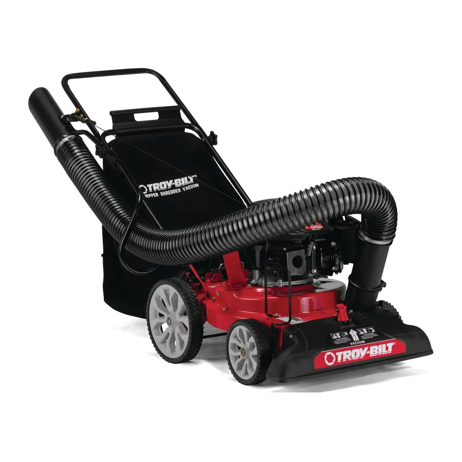
Yard vacuum/chipper/shredder with vacuum/hose
Hide thumbs
Also See for CSV 060:
- Operation manual (40 pages) ,
- Operator's manual (28 pages) ,
- Specifications (1 page)
Table of Contents
Advertisement
Available languages
Available languages
Advertisement
Table of Contents

Related Manuals for Troy-Bilt CSV 060


Summary of Contents for Troy-Bilt CSV 060
- Page 1 Safe Operation Practices • Set-Up • Operation • Maintenance • Service • Troubleshooting • Warranty ® ATOR S ANUAL Yard Vacuum/Chipper/Shredder with Vacuum/Hose Model CSV 060 TROY-BILT LLC, P.O. BOX 361131 CLEVELAND, OHiO 44136-0019 PrintedIn USA FormNo.769-03903 (JunelO,2008)
-
Page 2: Recordproduct Information
Chipper/Shredder Vacuum If you have any problems or questions concerning the machine, manufactured by Troy-Bilt LLC. It was carefully engineered phone a authorized Troy-Bilt service dealer or contact us directly. provide excellent performance when properly operated Troy-Bilt's Customer Support telephone... -
Page 3: Important Safe Operation Practices
Important SafeOperation Practices WARNING: This symbol points out important safety instructions which, if not followed, could endanger the personal safety and/or property of yourself and others. Read and follow all instructions in this manual before attempting to operate this machine. Failure to comply with these instructions may result in personal... - Page 4 If the impeller strikes a foreign object or if your machine SafeHandlingof Gasoline: should start making an unusual noise or vibration, To avoid personal injury or property damage use extreme care immediately shut the engine off. Allow the impeller in handling gasoline.
-
Page 5: Maintenance And Storage
Maintenance & Storage Donot modify engine Never tamper with safety devices. Check their proper To avoid serious injury or death, do not modify engine in any operation regularly. way. Tampering with the governor setting can lead to a runaway engine and cause it to operate at unsafe speeds. Never tamper Check bolts and screws for proper tightness at frequent with factory... -
Page 6: Safety Symbols
Safety Symbols This page depicts and describes safety symbols that may appear on this product. Read, understand, and follow all instructions on the machine before attempting to assemble and operate. READ THE OPERATOR'S MANUAL(S) Read, understand, and follow all instructions in the manual(s) before attempting assemble and operate... - Page 7 AssembJy & Set-Up Contents of Carton One Chipper/Shredder Vacuum One Operator's Manual One Engine Operator's Manual One Upper and Lower Handle One Hose Assembly One Safety Glasses One Bottle of Oil One Hose Extension One Bag Unfold the upper handle until it aligns with lower handle. Assembly Make sure the rope guide is on the right side of upper NOTE:This unit is shipped...
- Page 8 Pull the two cable ties attached to the cables tight Pull spring loaded pin out on the base and align pin with the first hole (closest to the end of the tube) in the hose approximately 8 inches from each cable end and place the cables into the cable guide.
- Page 9 Adjustments Grasp bag handle with one hand and slide locking rod on NozzleHeight mounting bracket with other hand toward engine. the end of mounting bracket as leverage when sliding the The nozzle can be adjusted to any six positions, ranging from locking rod.
-
Page 10: Controls And Features
Controls a nd Features Recoil Hose Handle Hose Assembly Hose Extension Nozzle Height Adjustment Lever Figure 4=1 HoseExtension WARNING: The operation of any chipper shredder can result in foreign objects being thrown into the Used to vacuum yard waste in hard to reach places of yard. eyes, which can damage your eyes severely. -
Page 11: Operation
Operation Repeat the previous steps until engine fires. When engine Starting Engine starts, move choke control (if equipped) gradually to RUN IMPORTANT:The bag/chute switch button must be fully position. depressed by the tip of front tab on bag handle or blower chute If engine falters, move choke control back toward... - Page 12 Grasp bag handle with one hand and pull lock rod on UsingTheNozzleVacuum mounting bracket with other hand toward engine to release. Yard waste such as leaves and pine needles can be vacuumed up through the nozzle for shredding. After material has been Lift bag off back of unit.
- Page 13 Unhook the hose from upper and lower hose handle UsingTheHoseAssembly brackets and grasp the hose handle to guide the hose Place nozzle/hose vac lever in the bottom position on the while vacuuming yard waste such as leaves or pine needles. nozzle to redirect vacuum to the hose assembly.
-
Page 14: Maintenance And Adjustments
Maintenance& Adjustments Maintenance Equipment Care Clean the chipper/shredder vacuum thoroughly after each General Recommendations use. Always observe safety rules when performing Wash bag periodically with water. Allow to dry thoroughly maintenance. in shade. The warranty on this chipper/shredder vacuum does not If the flail screen becomes clogged, remove and clean as... - Page 15 Remove and clean the screen by scraping or washing with Removing the Hail Screen water. See Fig. 6-3. If the discharge area becomes clogged, remove the flail screen and clean area as follows: Stop the engine. Make certain the chipper/shredder vacuum has come to a complete stop.
-
Page 16: Blade Care
Service Blade Care Front Support Brace/ Lock N ut maintenance on the machine, wait for all parts to WARNING: Pivot Arm Before performing any type of stop moving and disconnect the spark plug wire. Assembly "",, Failure to follow this instruction could result in personal injury or property... -
Page 17: Off-Season Storage
Carefully tilt and support the unit up to provide access The nuts on the flat head cap screws can be reached underneath to the nozzle mounting hardware and impeller. from underneath using a 1/2-inch socket, universal, and Remove the three shoulder bolts securing the black plastic extension. -
Page 18: Troubleshooting
Troubleshooting Problem Cause Remedy Engine runs erratic 1. Spark plug boot loose. 1. Connectand tighten spark plug boot. 2. Unit running on CHOKE (if equipped). 2. Move choke lever to OFF position. 3. Blocked fuel line or stale fuel. 3. Clean fuel line; fill tank with clean, fresh gasoline. - Page 20 ModelCSV 060...
- Page 21 Model C SV 060 Description I Part Part Number Description Number 723-0295 736-o314 Thrust Washer.375 ID x.70 OD Adjustment Clamp 749-1270A Nozzle Handle 749-04172 Upper Handle 720-0279 Knob 764-0648A Vacuum Hose 710-0599 720-0369 Screw, 1/4-20 x.500 Handle Plug 731-2292 710-1205 Hose Adapter Eye Bolt 712-0442...
- Page 22 ModelCSV 060...
- Page 23 Model C SV 060 Ref I Part Number Description Description I Part Number 732-1151A 664-04031 Bag Assembly Nozzle Door Torsion Spring 731-2294A Nozzle Door 681-0154 Screen Assembly 664-04029 710-1054 Hex Screw 5/16-24 x 1.0 631-0083 781-0490 Chipper Blade Chute Assembly 710-0726 781-0735 Hex Index Screw, 5/16-12 x.750...
-
Page 24: Limited Warranty
MANUFACTURER'S LiMiTED WARRANTY ® The limited warranty set forth below is given by Troy-Bilt LLC with c. Routine maintenance items such as lubricants, filters, blade respect to new merchandise purchased and used in the United States sharpening, tune-ups, brake adjustments, clutch adjustments,... - Page 25 Medidas importantes de seguridad • Configuraci6n • Funcionamiento • Mantenimiento • Servicio • Soluci6n de problemas • Garantia ® ANUAL Aspiradora Para Patios m Modelo CSV 060 TROY=BILT LLC, P.O. BOX 361131 CLEVELAND, OHiO 44136=0019 FormNo.769-03903 Impresoen Estados UnidosdeAmerica (JunelO,2008)
- Page 26 Si tiene algun problema o duda respecto a la unidad, Ilame a un distribuidor de servicio Troy-Bilt autorizado o p6ngase en Por favor lea todo este manual antes de operar el equipo. contacto directamente con nosotros.
-
Page 27: Medidas Importantes De Seguridad
Medidasimportantesde seguridad ADVERTENCIA" La presencia de este s[mbolo indica que se trata de instrucciones importantes de seguridad que se deben respetar para evitar poner en peligro su seguridad personal y/o material y la de otras personas. Lea y siga todas las instrucciones de este manual antes de poner en funcionamiento esta m_quina. - Page 28 Si el motor golpea un objeto extra_o o si la m_fiquina Manejo seguro de ia gasolina empieza a producir un sonido poco comun o una vibraci6n, Para evitar lesiones personales o dahos materiales apague el motor de inmediato. Deje que el motor se sumamente cuidadoso al manipular...
-
Page 29: Mantenimiento Y Almacenamiento
Avisoreferidoa emisiones Mantenimientoy almacenamiento Nunca manipule los dispositivos de seguridad de manera Los motores que est_n certificados y cumplen con las imprudente. Controle peri6dicamente que funcionen regulaciones de emisiones federales EPA y de California para forma adecuada. SORE (Equipos pequefos todo terreno) est_n certificados para... -
Page 30: Simbolos Deseguridad
Simbolos DeSeguridad Esta p_gina representa y describe la seguridad los simbolos que pueden parecer en este producto. Lea, comprenda, y siga todas instrucciones en la m_quina antes procurar para reuniry operar. LEA EL MANUAL(S) DEL OPERADOR Lea, comprenda, y siga todas instrucciones en el manual (manuales) antes procurar para reuniry... -
Page 31: Contenido De Ia Caja
Montajey Configuraci6n Contenido de ia caja Una Aspiradora Para Patios Uno Manual de Operador Uno Manual de Operador de Motor Una Manija superior e inferior Uno Montaje de la manguera Uno Anteojos de seguridad Una Bolsa Uno Botella del Aceite Uno Extensi6n de Manguera Despliegue... - Page 32 4. Tire delas dos uniones del c able u nidas alos cables, ajuste 2. Tire del perno con resorte del lado exterior de la base, aproximadamente 8pulgadas decada e xtremo decable, y y ponga el perno en linea con el primer agujero ubique l os cables ensu guia.
- Page 33 Bolsa Oprima la palanca de ajuste de la altura del pico hacia la rueda. Vea la fig. 3-7. Sostenga la manija de la bolsa con una mano y deslice la varilla de seguridad del soporte de montaje hacia el motor con la otra mano.
- Page 34 Controles Y Caractedsticas Arrancador de Retroceso manguera de la manguera tensibn de Manguera Palanca del pico / manguera de la _anija de la n al de la cortadora aspiradora Palanca de ajuste de la altura del pico Figura 44 ADVERTENCIA: AI operar una cortadora Montajede ia manguera trituradora puede ser que objetos extra_os sean...
- Page 35 Funcionamiento Encendido dei Motor Si el motor falla, mueva el control del obturador hacia atr_fis, en direcci6n al control del estrangulador, y repita los pasos 5a7. IMPORTANTE: El bot6n del interruptor de bolsa / canal debe quedar presionado totalmente pot la punta de la aleta delantera Mantenga SIEMPRE el control del estrangulador...
- Page 36 Tome la manija de la bolsa con una manoy tire de la varilla gsoDeiPicoDe[a Aspiradora de seguridad del soporte de montaje hacia el motor con la El desecho que se acumula en los patios como por ejemplo otra mano para soltarla. hojas y las agujas de los pinos pueden aspirarse a trav_s del Eleve la bolsa fuera de la parte posterior...
- Page 37 Desenganche la manguera del soporte de la manija UsoDeiMontaje DeLaManguera superior y tome la manija de la manguera para dirigirla Coloque la manija del pico/manguera de la aspiradora mientras aspira los desechos que se acumulan en los en la posici6n de la base del pico para volver a dirigir la patios como pot ejemplo hojas o agujas de pinos que se...
-
Page 38: Mantenimiento Y Ajustes
Mantenimiento Y Ajustes Mantenimiento Siga el manual de motor separado embalado por su unidad para instrucciones de lubricaci6n. Recomendadones6enerales Carede Equip0 Respete siempre las reglas de seguridad cuando realice Limpie cuidadosamente la aspiradora para patios despu&s tareas de mantenimiento. de cada uso. La garantia de esta aspiradora para patios no cubre... - Page 39 ADVERTENClA: Antes de realizarcualquier tipo del Saque el tornillo de cabeza hexagonal de la parte superior mantenimiento en la m_quina, espere todas las de la caja posterior cerca del soporte de montaje, y la tuerca de seguridad de la brida que une la pantalla partes a dejar de moverse y desconectar el alambre desgranado.
- Page 40 Servkio Cuidadode ia Cuchiila mantenimiento en la m_quina, espere todas las DVERTENCIA: Antes de realizarcualquier tipo del partes a dejar de moverse y desconectar el alambre de bujia. El fracaso de seguir esta instrucci6n podria causar la herida personal o el daho a la propiedad. Arandela NOTA: Cuando incline la unidad, vacie el dep6sito...
- Page 41 Incline la unidad con cuidado y ap6yela hacia arriba para Es posible alcanzar las tuercas de los tornillos de cabeza obtener acceso pot la parte inferior al material de montaje plana desde la parte inferior, mediante una Ilave universal del pico y al motor. Retire los tres tornillos con reborde de 1/2 pulg.
- Page 42 Solud6n deproblemas Problema Causa Remedio El motor funciona 1. La unidad est_ funcionando en la posici6n 1. Cambie la palanca de obturaci6n a la manera err_tica CHOKE (obturaci6n). posici6n OFF (apagado). 2. El cable de la bujia est_ flojo. 2. Conecte y ajuste el cable de la bujia. 3.
- Page 43 Problema Causa Rernedio Saltos ocasionales 1. La distancia disruptiva de la bujia es muy 1. Quite la bujia y ajuste el hueco. (pausas) a peque_a. alta velocidad 2. Consulte el manual del motor. 2. Ajuste de la mezcla del carburador real realizada.
- Page 44 Las disposiciones de esta garantia cubren el recurso de reparaci6n zapatas antideslizantes, ruedas de fricci6n, placas de raspado, gomas _nica y exclusiva que surge de la venta. Troy-Bilt no se har_ helicoidales y neum6,ticos. responsaMe de ninguna p_rdida o da_o incidental o resultante,...