Table of Contents
Advertisement
Quick Links
Safe Operation Practices • Set-Up • Operation • Maintenance • Service • Troubleshooting • Warranty
O
'
M
peratOr
s
anual
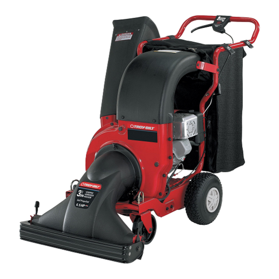
Chipper Shredder Vacuum
Model CSV 204
WARNING
READ AND FOLLOW ALL SAFETY RULES AND INSTRUCTIONS IN THIS MANUAL
BEFORE ATTEMPTING TO OPERATE THIS MACHINE.
FAILURE TO COMPLY WITH THESE INSTRUCTIONS MAY RESULT IN PERSONAL INJURY.
TROY-BILT LLC, P.O. BOX 361131 CLEVELAND, OHIO 44136-0019
Printed In USA
Form No. 769-05098
(August 6, 2009)
Advertisement
Table of Contents

Related Manuals for Troy-Bilt CSV 204


Summary of Contents for Troy-Bilt CSV 204
- Page 1 READ AND FOLLOW ALL SAFETY RULES AND INSTRUCTIONS IN THIS MANUAL BEFORE ATTEMPTING TO OPERATE THIS MACHINE. FAILURE TO COMPLY WITH THESE INSTRUCTIONS MAY RESULT IN PERSONAL INJURY. TROY-BILT LLC, P.O. BOX 361131 CLEVELAND, OHIO 44136-0019 Printed In USA Form No. 769-05098...
-
Page 2: Table Of Contents
Choose from the options below: ◊ Visit us on the web at www.troybilt.com ◊ Call a Customer Support Representative at (800) 828-5500 or (330) 558-7220 ◊ Write us at Troy-Bilt LLC • P.O. Box 361131 • Cleveland, OH • 44136-0019... -
Page 3: Safe Operation Practices
Important Safe Operation Practices WARNING: This symbol points out important safety instructions which, if not followed, could endanger the personal safety and/or property of yourself and others. Read and follow all instructions in this manual before attempting to operate this machine. Failure to comply with these instructions may result in personal injury. - Page 4 Safe Handling of Gasoline: If the impeller strikes a foreign object or if your machine should start making an unusual noise or vibration, To avoid personal injury or property damage use extreme care immediately shut the engine off. Allow the impeller to in handling gasoline.
- Page 5 Maintenance & Storage Do not modify engine Never tamper with safety devices. Check their proper To avoid serious injury or death, do not modify engine in any operation regularly. way. Tampering with the governor setting can lead to a runaway engine and cause it to operate at unsafe speeds.
- Page 6 Safety Symbols This page depicts and describes safety symbols that may appear on this product. Read, understand, and follow all instructions on the machine before attempting to assemble and operate. Symbol Description READ THE OPERATOR’S MANUAL(S) Read, understand, and follow all instructions in the manual(s) before attempting to assemble and operate WARNING—...
-
Page 7: Assembly & Set-Up
Assembly & Set-Up Contents of Carton • One Chipper Shredder Vacuum • One Operator’s Manual • One Engine Operator’s Manual • One Chipper Chute • One Nozzle • One Safety Glasses • One Bag • One Tamper (If Equipped) • One Bottle of Oil Assembly NOTE: This unit is shipped without gasoline or oil in the engine. - Page 8 Remove the three hex nuts and bell washers from the weld studs beside the opening on the right side of the chipper- Place bag under the upper handle assembly and slip the shredder vacuum. See Fig. 3-3B. front opening on the bag over the discharge chute, making Place the chipper chute over the weld studs keeping the certain it is over the rim on the discharge chute.
- Page 9 Adjustments Front Caster Wheels This chipper shredder vacuum is equipped with front caster Nozzle Height wheels. The casters can be locked in a straight ahead position or to swivel freely. The nozzle adjustment levers are located on each side of the nozzle door.
-
Page 10: Controls & Features
Controls and Features Chipper Chute Drive Control Vacuum/ Chipper Caster Lock Nozzle Door Adjustment Lever Figure 4-1 Vacuum/Chipper Bag WARNING: Be familiar with all controls and their proper operation. Know how to stop the machine Collects shredded or chipped material fed through the chipper and disengage them quickly. -
Page 11: Operation
Operation Starting Engine Repeat the previous steps until engine fires. When engine starts, move choke control (if equipped) gradually to RUN WARNING: Keep bystanders, helpers, pets, and position. children at least 75 feet from the machine before NOTE: See your engine manual packed with your unit for starting and while operating. -
Page 12: Maintenance & Adjustment
Maintenance & Adjustments Maintenance Engine Care • Refer to the separate engine manual for all engine General Recommendations maintenance instructions. • Always observe safety rules when performing any • Check engine oil level before each use as instructed in the maintenance. - Page 13 Adjustments Remove the two hex bolts and hex nuts which extend through the impeller housing. See Fig. 6-2A. Drive Control Cable Periodic adjustment of the drive control cable may be required if: • The chipper shredder vacuum moves forward with the drive control disengaged.
-
Page 14: Service
Service Blade Care Remove other blade in the same manner to replace or sharpen. WARNING: Before performing any type of WARNING: Use caution when replacing the blades. maintenance on the machine, wait for all parts to Wear heavy gloves to avoid injury while handling stop moving and disconnect the spark plug wire. -
Page 15: Troubleshooting
Troubleshooting Problem Cause Remedy Engine Fails to start Throttle lever not in correct starting position. Move throttle lever to FAST or START position. Spark plug wire disconnected. Connect wire to spark plug. Choke not in CHOKE position (if equipped). Move choke lever to CHOKE position. Fuel tank empty or stale fuel. -
Page 16: Illustrated Parts List
Model CSV 204... - Page 17 Model CSV 204 Part Number Description Part Number Description 781-0633 Chute Flap Strip 723-0438 Rubber Seal 710-0604A Hex Washer Screw, 5/16-18 735-0249 Chute Flap 912-0384 Hex Lock Nut, 1/2-13 728-0175 Pop Rivet 781-0627-0638 Chipper Blade Cover 731-1838A Discharge Chute 712-3004A...
- Page 18 Model CSV 204...
- Page 19 Model CSV 204 Part Number Description Part Number Description 781-0677-0637 Chain Case - LH 731-1059 Mounting Cable Cap 710-1331 Screw, #10-16 x 1.25 781-0676-0637 Chain Case - RH 710-0805 Hex Cap Screw, 5/16-18 x 1.50 954-0457 V-Belt 936-0451 Shldr. Washer, .320 ID x.93 OD...
- Page 20 Model CSV 204 Part Number Description Part Number Description 741-0479 Thrust Bearing, .375 ID x.812 OD 941-0415 Flange Bearing.566 ID 956-0008 Idler Pulley Assembly W/ Bearing 918-0255 Shredder Transmission Assembly 956-0558 Idler Pulley Only 16500A-0637 Hex Bearing Cup 941-0556 Needle Bearing Only...
- Page 21 Notes...
-
Page 24: Warranty
MANUFACTURER’S LIMITED WARRANTY FOR The limited warranty set forth below is given by Troy-Bilt LLC with c. Routine maintenance items such as lubricants, filters, blade respect to new merchandise purchased and used in the United States sharpening, tune-ups, brake adjustments, clutch adjustments,...