Advertisement
Quick Links
www.nordictrack.com
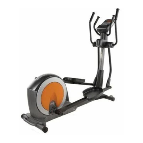
ModelNo.NTEL05609.0
Serial No.
Write the serial number in the
space above for future reference.
_jjj
DeSa_ri(alNu?ber e)
QUESTIONS?
If you have questions, or if parts are
damaged or missing, DO NOT
CONTACT THE STORE; please
contact Customer
Care.
iMPORTANT: Please register this
product (see the limited warranty
on the back cover of this manual)
before contacting
Customer Care.
CALL TOLL-FREE:
1-888-825-2588
Mon.-Fri.,
6 a.m.-6
p.m. MT
Sat. 8 a.m.-4
p.m. MT
ON THE WEB:
www.nordictrackservice.com
A UAL
Advertisement

Related Manuals for NordicTrack E5 vi NTEL05609.0


Summary of Contents for NordicTrack E5 vi NTEL05609.0
- Page 1 ModelNo.NTEL05609.0 A UAL Serial No. Write the serial number in the space above for future reference. _jjj DeSa_ri(alNu?ber e) QUESTIONS? If you have questions, or if parts are damaged or missing, DO NOT CONTACT THE STORE; please contact Customer Care.
- Page 2 • Spinning pedals can cause injury. • Reduce pedal speed in a controlled manner. , User weight must not exceed 300 pounds. • Replace label if damaged, illegible, or removed. NordicTrack is a registered trademark of ICON IP, Inc.
- Page 3 iMPORTANT PRECAUTIONS...
- Page 4 BEFORE YOU BEGIN Thank you for selecting the revolutionary NordicTrack ® cover of this manual. To help us assist you, note the E5 Vl elliptical exerciser. The E5 Vl elliptical exerciser product model number and serial number before con- provides an impressive selection of features designed tacting us.
- Page 5 ASSEMBLY Assembly requires two persons. Place all parts of the elliptical exerciser in a cleared area and remove the packing materials. Do not dispose of the packing materials until assembly is completed. in addition to the included tool(s), assembly requires a Phillips screwdriver and a rubber mallet c__.
- Page 6 Identify and orient the Front Stabilizer (3) as shown. While another person lifts the Frame (1), attach the Front Stabilizer (3) to the Frame with two MIO x 80mm Patch Screws (100) and two MIO Split Washers (123). Identify and orient the Rear Stabilizer (4) as shown.
- Page 7 Identify and orient the Upright (5) and the Top Cover (23) as shown. Slide the Top Cover upward onto the Upright. Wire Tie Have a second person hold the Upright (5) and the Top Cover (23) near the Frame (1). Locate the wire tie in the Upright (5).
- Page 8 Apply a generous amount of the included grease to the Upright Axle (48) and to two Small Wave Washers (118). Insert the Upright Axle (48) through the Upright (5) and center it. Slide a Small Wave Washer (118) onto each side of the Upright Axle. Identify the Right and Left Upper Body Legs (6, Grease 7), which are marked with "Right"...
- Page 9 Identify the Right Pedal (14), which is marked with a "Right" sticker, and orient it as shown. Attach the Right Pedal (14) to the Right Pedal Arm (12) with four M6 x 12mm Patch Screws (111) and four M6 Split Washers (112). Attach the Left Pedal (15) to the Left Pedal Arm (13) in the same way.
- Page 10 Identify the Right Handlebar (10), which is marked with a "Right" sticker, and orient it as shown. Avoid pinching the Have a second person hold the Right Handlebar Pulse Wire (34) (10) near the right side of the Upright (5). Locate the indicated wire tie in the Upright (5).
- Page 11 10. While a second person holds the Console (33) near the Upright (5), connect the console wires to the Wire Harness (60) and to the Pulse Wires Avoid pinching (34). the wires Insert the excess wire into the Console (33). onsole Wires Tip: Avoid pinching the wires.
- Page 12 12. Attach the Front Upright Cover (25) around the Upright (5) by pressing the tabs on the Front Upright Cover into the Rear Upright Cover (24). 13. Identify the Right Rear and Front Leg Covers (29, 30), which are marked with "Right" stickers. Attach the Right Rear Leg Cover (29) to the Right Upper Body Leg (6) with three M4 x 16mm Round Head Screws (106).
- Page 13 HOW TO USE THE ELLiPTiCAL EXERCISER HOW TO FOLD AND UNFOLD THE ELLiPTiCAL HOW TO MOVE THE ELLIPTICAL EXERCISER EXERCISER To move the elliptical exerciser, first fold it as When the elliptical exerciser is not in use, the frame described at the left. Next, stand in front of the ellipti- can be folded out of the way.
- Page 14 HOW TO EXERCISE ON THE ELLiPTiCAL EXERCISER To mount the elliptical exerciser, hold the upper body arms or the handlebars and step onto the pedal that is in the lowest position. Next, step onto the other pedal. Push the pedals until they begin to move with a con- Upper Body tinuous motion.
- Page 15 CONSOLE DIAGRAM BD,:B9 DIGITAL RESISTANCE -1 + FEATURES OF THE CONSOLE achieve specific fitness goals. For example, lose unwanted pounds with the 8-week Weight Loss work- This console offers an array of features designed to out. iFit workouts control the resistance of the pedals make your workouts more effective and enjoyable.
- Page 16 HOW TO USE THE MANUAL MODE The lower right display--The lower Begin pedaling or press any button on the right display can console to turn on the console. show the your ped- aling speed in A moment after you begin pedaling or press a but- revolutions per ton, the display will light.
- Page 17 Measure your heart rate if desired. If the display does not show your heart rate, make sure that your hands are positioned as described. if there are sheets Be careful not to move your hands excessively or of clear plastic on Contacts to squeeze the metal contacts tightly.
- Page 18 HOW TO USE A PRESET WORKOUT At the end of each segment of the workout, a series of tones will sound and the next segment of Begin pedaling or press any button on the the profile will begin to flash, If a different resis- console to turn on the console.
- Page 19 HOW TO USE A CALORIE GOAL WORKOUT At the end of each segment of the workout, a series of tones will sound and the next segment of Begin pedaling or press any button on the the profile will begin to flash. If a different resis- console to turn on the console.
- Page 20 HOW TO USE AN IFIT WORKOUT HOW TO USE THE SOUND SYSTEM iFit cards are available separately. To purchase iFit To play music or audio books through the console's cards, go to www.iFit.com or see the front cover of this sound system while you exercise, plug the audio cable manual, iFit cards are also available at select stores.
- Page 21 MAINTENANCE AND TROUBLESHOOTING Inspect and tighten all parts of the elliptical exerciser Next, locate the Reed Switch (69). Loosen, but do not regularly. Replace any worn parts immediately. remove, the M4 x 16mm Screw (93). To clean the elliptical exerciser, use a damp cloth and a small amount of mild soap.
- Page 22 HOW TO ADJUST THE DRIVE BELT Loosen the Pivot Screw (97). Then, tighten the Belt Adjustment Screw (85) until the Drive Belt (38) is tight. If you can feel the pedals slip while you are pedaling, even when the resistance is adjusted to the highest level, the drive belt may need to be adjusted.
- Page 23 EXERCISE GUiDELiNES Burning Fat--To burn fat effectively, you must exer- cise at a low intensity level for a sustained period of time, During the first few minutes of exercise, your body uses carbohydrate calories for energy. Only after the first few minutes of exercise does your body begin to use stored fat calories for energy, if your goal is to burn fat, adjust the intensity of your exercise until your heart rate is near the lowest number in your training...
- Page 24 PART LIST=Model No. NTEL05609.0 RogogA Key No. Qty. Description Key No. Qty. Description Frame Latch Spring Latch Insert Folding Frame Front Stabilizer Adjustment Arm Spring Rear Stabilizer Leg Bearing Assembly Leg Spacer Upright Axle Cover Right Upper Body Leg Left Upper Body Leg Upright Bushing Right Upper Body Arm Pedal Arm Bushing...
- Page 25 Key No. Qty. Description Key No. Qty. Description Anchored Zip Tie Large Snap Ring M8 x 16mm Patch Screw M4 x 19mm Flat Head Screw Small Wave Washer M8 Split Washer M10 x 60mm Button Screw Medium Wave Washer M10 Locknut M8 x 16mm x 2mm Washer M8 x 23mm Shoulder Patch Screw M4 x 16mm Round Head Screw...
- Page 26 r" ,102 ,.-4 r" ¢0 r..o r..o >...
- Page 27 r" 107 108 ,.-4 !1"! r" ¢0 r..o r..o 3>...
- Page 28 ORDERING REPLACEMENT PARTS To order replacement parts, see the front cover of this manual. To help us assist you, please be prepared to provide the following information when contacting us: o the model number and serial number of the product (see the front cover of this manual) o the name of the product (see the front cover of this manual) o the key number and description of the replacement part(s) (see the PART LIST and the EXPLODED DRAWING near the end of this manual)