Table of Contents
Advertisement
Available languages
Available languages
perator's
nual
I:RnFrSMRN°
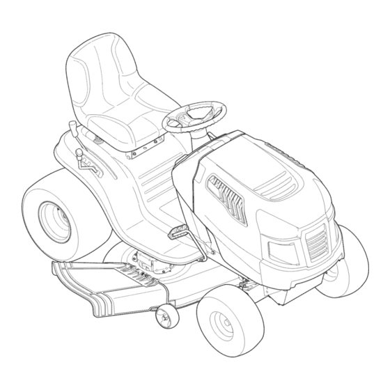
LAWN TRACTOR
21 HP, Variation Speed
46" Deck
Model No. 247.288853
• Espanol,
P. 58
This product
has a low emission
engine
which operates
differently
from
previously
built engines.
Before
you start the engine,
read and
understand
this Operator's
Manual.
Before
using this equipment,
read this manual
and follow
all safety
rules and operating
instructions.
For answers
to your questions
about
this product,
call:
1-800=659=5917
Craftsman Tractor Help Line
7 am = 7 pm CT, Mort. =Sun.
Sears Brands
Management
Corporation,
Hoffman
Estates,
IL 60179 U.S.A.
Visit our website:
www.craftsman.com
Form No.769-06474E
(December 6,2012)
Advertisement
Table of Contents

Related Manuals for Craftsman 247.288853


Summary of Contents for Craftsman 247.288853
- Page 1 I:RnFrSMRN° LAWN TRACTOR 21 HP, Variation Speed 46" Deck Model No. 247.288853 • Espanol, P. 58 This product has a low emission engine which operates differently from previously built engines. Before you start the engine, read and understand this Operator's Manual.
- Page 2 Withproofofpurchase, a newcastiron frontaxlewillbe supplied freeofcharge. WARRANTYSERVICE Forwarrantycoveragedetailsto obtainfree repairor replacement, c all 1-800-659-5917 or visit the website: www.craftsman.com in all casesabove,if part repairor replacement i simpossible, the ridingequipmentwill be replacedfree of chargewith the sameor an equivalent model.
- Page 3 This machinewas builtto be operatedaccordingto the safeopera- This symbolpointsout importantsafetyinstructionswhich,if not tion practicesin this manual.As with anytype of powerequipment, followed,couldendangerthepersonalsafetyand/orpropertyof carelessnessor error on the partof the operatorcan resultin serious yourselfand others. Readand followall instructionsin this manual injury.This machineis capableof amputatingfingers,hands,toes beforeattemptingto operatethis machine.Failureto complywith and feet and throwingdebris.Failureto observethe followingsafety these instructionsmay resultin personalinjury.Whenyou seethis...
- Page 4 SLOPE OPERATION • Slowdownbeforeturning.Operatethe machinesmoothly.Avoid erraticoperationand excessivespeed. Slopesare a majorfactorrelatedto loss of controland tip-over Disengageblade(s),set parkingbrake,stopengine and wait until accidentswhichcan result in severeinjuryor death.All slopes require the blade(s)come to a completestop beforeremoving grass extra caution.If youcannot back up the slopeor if youfeel uneasyon catcher,emptyinggrass,uncloggingchute,removinganygrass or it, do not mowit.
- Page 5 CHILDREN SERVICE Tragicaccidentscanoccur ifthe operatoris notalert to the presence SafeHandlingof Gasoline of children.Childrenare often attractedto the machineand the mowing Toavoidpersonalinjury or propertydamageuse extremecarein activity.They do notunderstandthe dangers.Neverassumethat handlinggasoline.Gasolineisextremelyflammableand the vaporsare childrenwill remainwhereyou last sawthem. explosive.Seriouspersonalinjury canoccur whengasolineis spilled • Keepchildrenout of the mowingareaand inwatchfulcare of a on yourselfor your clotheswhich can ignite.
- Page 6 General Service • Donot changethe enginegovernorsettingsor over-speed the • Never run anengine indoors orina poorly ventilated area. Engine engine.The governorcontrolsthe maximumsafe operatingspeed exhaust contains carbon monoxide, anodorless, and deadly gas. of the engine. • Before cleaning, repairing, orinspecting, make c ertain the Maintainor replacesafetyand instructionlabels,as necessary.
- Page 7 SAFETY SYMBOLS This pagedepictsand describessafety symbolsthat may appearon this product. Read,understand,and follow all instructions on the machine beforeattemptingto assembleand operate. READ THE OPERATOR'S MANUAL(S) Read, understand, and follow all instructions in the manual(s) before attempting to assemble and operate DANGER-- ROTATING BLADES Never carry passengers.
- Page 8 15° Slope 15° Slope (OK) (TOO STEEP) '_. _ Figure 1 Figure 2 15° dashed line USETHISSLOPE GAUGE TODETERMINE IF A SLOPE IS TOOSTEEPFORSAFEOPERATION! To checkthe slope, proceedas follows: Removethis pageand fold along the dashedline. Locatea verticalobject on or behindthe slope (e.g. a pole, building,fence, tree, etc.) 3.
- Page 9 IM PORTANT: Your t ractor i sshipped w ithmotor o il intheengine. However, Shipping BraceRemoval youMUST check t heoillevel b efore o perating. Refer totheService & Maintenance section f orinstructions onchecking theoillevel. Makesurethe riding mower'sengine isoff, removethe ignition key,and NOTE: Any referencein this manualto the RIGHTor LEFTside of the set the parkingbrake before removing the shipping brace.Referto the tractoris observedfrom operator'sseat positionfacing forwardtowards thefront of tractor.
- Page 10 Adjusting the Seat Toadjustthe positionof the seat,pull upandholdthe seatadjustmentlever. S lide the seatforwardor rearwardto the desired position;thenrelease the adjustment lever. M akesureseatis locked into positioninaseat-stop beforeoperating the tractor.SeeFigure 5. Beforeoperatingthe tractor, makesurethe seat isengaged ina seat-stop. Engage the parkingbrake.Stand behindthe machineand pull backon seat until it clicksintoplace.
- Page 11 Seat A djustment L ever Deck Lift Lever Brake Pedal NOTE: Any referencein this manualto the RIGHTor LEFTside of the tractoris observedfrom operator'sseat positionfacingforwardtowardsthe frontof tractor. Meets ANSi S afetyStandards Craftsman T ractors conform to the safetystandard ofthe American National S tandards I nstitute(ANSI).
- Page 12 ParkingBrakeLever SeatAdjustmentLever Tosetthe parkingbrake:Fullydepress t he brakepedal.Movethe Theseatadjustment l everislocatedbelowthe front/left of the seat.Thelever parkingbrakeleverintothe parkingbrakeposition.Release t he allowsforadjustment o f the foreandaft positionof the seat.Refer t o the Assembly brakepedalto allowthe parkingbrake to engage. sectionof the manualformoredetailedinstructions foradjustingthe seatposition. Torelease the parkingbrake: D epress t he brakepedalandthe Auto-drivepedal parkingbrakeleverwill moveout of the parkingbrakepositionon...
- Page 13 Gasand Oil Fill-up IMPORTAfl# Your t ractorisshippedwith motoroil intheengine.However, you MUST check the oil levelbefore operating. B ecareful n ot tooverfill. Forinstructionsonhowto check the engineoil,referto Checking TheEngine Oilin the Service a ndMaintenance s ectionof thismanual. Gasoline Thegasoline tank islocatedunderthe hood.Donotoverfill. Useextreme carewhen handling gasoline.Gasolineisextremelyflammable andthe vaporsareexplosive.Neverfuel machineindoors or while the engine ishot or running.
- Page 14 Theenginewill automatically s hut off if the PTO (Blade Engage) l everis Setting the Cutting Height movedintothe engaged (ON)positionwith the shift leverinReverse. Select t he heightpositionof the cuttingdeckbyplacingthe decklift leverin Ignition Switch anyof thedifferentcutting heightnotches on the rightsideof the fender. Adjustthe deckwheelssothatthey arebetweenl_-inchand1/2-inch a bove Theignition switchis activated to startthe engine.Insertkeyinto the ignition the groundwhenthe tractorison asmooth, f lat surface suchasadriveway.
- Page 15 DrivingTheTractor DoNOThold the key in the START positionfor longerthan ten seconds at a time. Doingsomay causedamageto your engine's electric Avoidsuddenstarts, excessive speedandsuddenstops. starter. Afterthe enginestarts,deactivate the chokecontrol a ndplace the throttle Donot leavethe seatof the tractor without first placingthe PTO (Blade control i n the FAST p osition.
- Page 16 DrivingOnSlopes Mowing Referto the SLOPE GAUGE i nthe SafetyInstructions sectionofthe manual t o help determineslopes whereyoumayoperatethistractorsafely. Tohelpavoid bladecontactor athrown object injury, keepbystanders, helpers,children andpets at least 75; f eet from the machinewhile it is in operation. Stopmachineif anyoneentersthe area. Donot mow on inclines w ith a slope inexcess of 15degrees(a riseof approximately2-112 feet every 10feet).
- Page 17 MAINTENANCE SCHEDULE Beforeperforming anytype of maintenance/service, d isengageall controls Follow the maintenance s chedule givenbelow.Thischartdescribes s ervice andstop the engine.Wait until all moving partshavecometo a complete guidelines only.Use the Service Logcolumn to keeptrackofcompleted stop.Disconnect sparkplug wire andgroundit againstthe engine to prevent maintenance t asks.Tolocate the nearestParts &...
- Page 18 ChangingEngine Oil Engine Maintenance Theengineoil shouldbechanged in the first 5hoursandthenevery50 hours or Checking the Engine Oil onceaseason. Tochange the engineoil,proceed asfollows: Onlyusehighqualitydetergentoil ratedwith APIservice classification S F, S G, With engineOFF but still warm,disconnect sparkplugwire andkeepit away SH, o r SJ. S elect t he oil'sSAE viscosity gradeaccording to the expected operating from sparkplug.
- Page 19 Fuel Filter Air (:leaner Theairfilter systemuses acylindrical c artridge. Remove t he fasteners CA) andthe air filter cover(B).SeeFigure 13. Gasolineanditsvapors areextremely flammable andexplosive.Fireor explosioncancause severe burnsor death. Toremove the filter (C),lift the endof the filter andthenpullthe filter off the intake (D). Keep gasoline awayfrom sparks, o penflames,pilot lights,heat,andother Toloosen debris,gentlytap the filter onahardsurface.
- Page 20 Muffler IMPORTANT; If removing the batteryforanyreason, d isconnect the NEGATIVE (Black) w irefrom itsterminalfirst, followedbythe POSITIVE (Red) w ire. When re-installingthe battery,alwaysconnect t he POSITIVE (Red) w ire to itsterminal first, followedbythe NEGATIVE (Black) w ire. Becertainthat the wiresareconnected Temperature of muffler andnearbyengine areasmayexceed150 ° F(65°C). Avoidcontactwith theseareas.
- Page 21 Movethe tractor'sPTO (Blade Engage) intothe ONposition. Measure the distance fromthe front of the bladetip to the groundandthe rearof the bladetip tothe ground.Thefirst measurement takenshould Remainintheoperator'spositionwiththecuttingdeckengaged foraminimumof be between14" and98" lessthanthe second measurement. Determine two minutes, a llowingthe underside of the cuttingdeckto thoroughlyrinse. the approximate distance necessary for properadjustment a ndproceed, if Movethe tractor'sPTO (Blade Engage) into the OFF position.
- Page 22 Retighten the hexcapscrew on the left deckhanger b racket w hen proper adjustment i sachieved. Avoid pinching injuries. N everplaceyourfingers on the idlerspringor betweenthe belt and a pulley while removingthe belt. Hex Cap Screw Figure 17 SeatAdjustment Referto theAssembly sectionof thismanual f or seatadjustmentinstructions. Figure18 Parking BrakeAdjustment Looking atthe cuttingdeckfrom the left sideof the tractor,locatethe bow-...
- Page 23 Remove t he bow-tiecotterpinsecuring the deckstabilizerrodto the deck. The recommended operating tire pressureis: Slide the decklift rodfromthe mountingbracket o n the deckasshownin Approximately 10psiforthe reartires Figure 20. Approximately14psiforthe front tires IM PORTANT: Refertothe tire sidewall forexact tire manufacturer's .._Y'k ....
- Page 24 If yourtractorhasnot beenput into useforan extended periodof time,charge the Toproperlysharpen the cuttingblades, r emove equal a mounts of metal batteryasfollows: from bothendsof the bladesalongthe cuttingedges, p aralleltothe trailing Setyourbatterycharger t o deliveramaxof 10amperes. edge,at a25°- to 30°angle.Always grindeachcutting bladeedgeequallyto maintainproperbladebalance. SeeFigure 23. If yourbatterychargerisautomatic, c harge the batteryuntil the charger indicates that charging iscomplete.
- Page 25 Tochangeor replace the deckbelton yourtractor,proceed asfollows: ParkingBrakeAdjustment Remove t he deckasinstructed earlierinthissection. Remove t he belt covers fromthe spindlepulleys byremoving the hexscrews Neverattempt to adjustthe brakeswhilethe engine is running. A lways thatfastenthe covers to the deck.SeeFigure 24. disengagePTO (BladeEngageLever), m oveshift leverinto neutral position, It mayalsobenecessary t o loosenthe hexnut onthe left deckidlerpulleyto stop engine and removekeyto preventunintended starting.
- Page 26 Neverstore lawn tractor with fuel in tankindoors or in poorlyventilated areaswhere fuel fumes may reachanopen flame, spark,or pilot light ason a furnace,water heater, clothesdryer,or gasappliance. PreparingTheEngine DrainingThe Fuel IM PORTANT: Fuel l eft inthe fueltank duringwarmweatherdeteriorates a nd Locate the fuel filter,whichis located on the left sideofthe engine,andmay will cause serious startingproblems.
- Page 27 Enginefails to start PTO/BladeEngageleverengaged. Placeleverin disengaged(OFF) position. Parkingbrakenotengaged. Engageparkingbrake. Sparkplugwire(s) disconnected. Connectwire(s) to sparkplug(s). Throttle/Chokecontrollevernot in correct PlaceThrottle/Chokeleverintothe FASTposition. startingposition. Chokenotactivated MovetheThrottle/Chokeleverintothe Choke position. Fueltank empty,or stale fuel. Filltank with clean,fresh (less than 30 days old) gas. Blockedfuel line. Replacethe fuel line and replacefuel filter. Faultysparkplug(s).
- Page 28 777X46404 777D18558 777D17036 777D15654 777D18559 Ce.tersorcall1-800-366-PART(7278) if yo.want t ilepart i specmc tractor attachlnent_ lot yo.r Crattslnan tractoravailableat SearsStoresandService Cenlers. Seebelow for other u ,i_e_al atladlments al_o availahlem Descr|_tjon Stock Ho. BumperKit | 24011 777[23592 WeightKit [ 24041 _. Weight | 24027 777D15546 777S33818...
- Page 29 This page intentionally left blank. Use this page to make any notes regarding your tractor.
- Page 30 Craftsman IViodel 247.288853 / 34 62._...
- Page 31 Craftsman Model 247.288853 Part No, Description Part No, Description Ref, Ref, 925-1649 Bulb Socket 741-0587 Steering Column Bearing 712-04063 Nut, Hex Flange Lock, 5/16-18 683-04619A-0691 Hood Assembly 783-06785A Screw, 5/16-18 x .750 Steering Support Bracket 710-04484 783-06811-0637 Dash 710-0599 Hex Washer Screw, 1/4-20 x .500...
- Page 32 Craftsman Model 247.288853 7 29...
- Page 33 Craftsman Model 247.288853 Ref. Part No. Description Part No. Description Ref. 683-04334 756-04196A Shaft,Lift Engagement P ulley 712-04065 747-04857 Nut,Hex FlangeInsert Lock,3/8-16 Belt KeeperRodAssembly 714-04040 710-04484 Bow-TiePin,91, RH Screw,Hd.Tapp, 5 /16-18x .75 716-0106A 683-04195-0637 E-ring,.625Shaft Support BracketAssembly 720-0298 683-04649A-0637 Grip,Handle...
- Page 34 Craftsman IViodel 247.288853 _J31 34._ _ __\\"-_...
- Page 35 Craftsman Model 247.288853 Part No. Description Part No, Description Ref, Ref, 617-04094 710-04484 Gear Assembly, Steering Screw, 5/16-18, 0.750 710-0643 712-04065 Screw, 5/16-18, 1.00, Gr5, Lock Nut, Flange Lock, 3/8-16, GrF 714-0162 710-I 309 Screw, Mach, 5/16-18, 0.750 Pin, Cotter, 5/32, 1.25...
- Page 36 Craftsman Model 247.288853...
- Page 37 Craftsman Model 247.288853 Part No. Description Ref, 710-04482 Hex Flange Bolt, 3/8-16 x .875 710-04484 Screw, Hd.-lapp, 5/16-18 x .75 712-3004A Flange Lock Nut, 5/16-18 925-05013 Seat Safety Switch 757-04145 Seat 926-0154 Push Mount Cable Tie 732-04035 Spring, Compress., 1.28 x 3.125 732-04563 Spring, Compress., .68 x 1.065 x .055...
- Page 38 Craftsman IViodel 247.288853...
- Page 39 Craftsman IViodel 247.288853 Ref. Description Part No. 683-04549-0637 MufflerShieldAssembly 710-0227 Screw,AB #8-180.500 710-04683A TapScrew,3/8-16 1.000 710-0642 TapScrew,1/4-200.750 710-1314A Screw,SocketHead,5/16-18 x .750 712-0271 Sems Nut, 1/4-20 BS-692236 ExhaustGasket 725-0157 CableTie,3/16 X .05 X 7.4 726-0205 HoseClamp,.490 Dia. 731-05628 Oil DrainSleeve 751-10349...
- Page 40 Craftsman IViodel 247.288853 5"...
- Page 41 Craftsman Model 247.288853 Ref. I Ref, Description Part No. Description Part No, 918-04566 736-3040 Flat Washer, .406 x 1.920 x .060 Transmission Drive Assembly 936-0185 17962 Plate Switch Flat Washer, .375 X .738 X .063 725-04363 Switch Interlock 647-04266 Shaft Lever Assembly...
- Page 42 Craftsman Model 247.288853 24 \ "58...
- Page 43 Craftsman Model 247.288853 Ref. I Part Number Ref. I Part Number Description Description 738-04278 918-04865A Shoulder Screw, 1/4-20 x 0.50 Spindle Assembly, Pul 6.93 Dia 683-0254B 736-0262 Washer, Flat, .385 x .870 x .092 Bracket Assembly, Deck Hanger, LH 631-04288...
- Page 44 Craftsman Engine Model 331877=0869=G5 For Model 247.288853 1330 REPAIR MANUAL 48 SHORT BLOCK 1058 OPERATOR'S MANUAL I1329 REPLACEMENT ENGINE ] 11 ,_ ..-/_. __ 1264 1263 552 _ 691 _ ion., 5 05 _-,'-_ ¢,_ 562 _ _" 1017_i_2_ _-'-._ _ i...
- Page 45 Craftsman Engine Model 331877=0869=G5 For Model 247.288853 186A 415A 1022 635_ i1029} 1026 _ 654 _ 53 ..
- Page 46 Craftsman Engine Model 331877-0869-G5 For Model 247.288853 13o 1 95 '_ _ 1270 1091 {{L# 276 <_') 1127 276 '-<_ 1266...
- Page 47 Craftsman Engine IViodel 331877=0869=G5 For IViodel 247.288853 1036 EMiSSiONS LABEL 1265 UZ_--.. 305A -.. 7_', 305B 1139 _._, ,324 i 415 _// :!!!i!!--_ 78 _¢ 1005 '_f_ 1044...
- Page 48 Craftsman Engine IViodel 331877-0869-G5 For IViodel 247.288853 1119 1051 <" 462 _; ,,,_/...
- Page 49 Craftsman Engine Model 331877=0869=G5 For Model 247.288853 121 CARBURETOR OVERHAUL lO5 0 61_ _ , 104 _ 127 (_' 987 4_b 1266 _ ;_" 358 ENGINE GASKET SET 1o22 691 _'7//' 1266 1095 VALVE GASKET SET 1022...
- Page 50 Craftsman Engine Model 331877=0869=G5 For Model 247.288853 Ref. Ref, I Part No. Description I Part No, Description 794128 695408 Cylinder Assembly Kit-Idle Speed 399265 694918 Bushing/Seal Kit (Magneto Side) Pin-Float Hinge 391086s Seal-Oil (Magneto Side) 696136 Valve-Float Needle 697188 Sump-Engine...
- Page 51 Craftsman Engine Model 331877-0869-G5 For Model 247.288853 Ref. Ref. I Part No. Description Description I Part No. 690323 697392 Screw (Starter Motor) Pin-Counterweight 497608 Brush Set 796448 Retainer (Fuel Pump) 796309 693713 Gear-Pinion Screen/Cup Assembly 795315 698329 Armature-Magneto Harness-Wiring 691061...
- Page 52 Craftsman Engine Model 331877=0869=G5 For Model 247.288853 Ref, I Part No. Description 1091 691333 Cap-Limiter 1095 794152 Gasket Set-Valve 1119 691183 Screw (Alternator) 1127 695407 Screw (Float Bowl) 1139 796449 Washer (Fuel Pump) 1263 697124 Reed-Breather 1264 697104 Screw (Breather...
- Page 53 Look For Relevant Emissions Durability Period and Air index information On Your Engine Emissions Label Engines that are certified to meet the California Air Resources Board (CARB) Tier 2 Emission Standards must display information regarding the Emissions Durability Period and the Air Index. Sears Brands Management Corporation makes this information available to the consumer on our emission...
- Page 54 (Thispage applicablein the U.S.A.and Canadaonly.) Sears Brands Management Corporation (Sears), the California Air Resources Board (CARD) and the United States Environmental Protection Agency (U.S. EPA) Emission Control System Warranty Statement (Owner's Defect Warranty Rights and Obligations) EMISSIONCONTROL WARRANTY COVERAGEISAPPLICABLE TO CERTI- YEAR 1997AND LATERENGINES WHICHARE PURCHASED AND USED FIEDENGINESPURCHASEDIN CALIFORNIAIN 1995ANDTHEREAF- ELSEWHERE IN THE UNITEDSTATES (ANDAFTERJANUARY1,2001 IN...
- Page 55 FEDERAL and/or CALIFORNIA EMISSION CONTROL W ARRANTY S TATEMENT YOUR WARRANTY RIGHTS ANDOBLIGATIONS MTD Consumer Group Inc, the United States Environmental Protection Agency (EPA), and, for those products certified for sale in the state of California, the California Air Resources Board (CARB) are pleased to explain the emission (evaporative and/or exhaust) control...
- Page 56 10. Add-on o rmodified parts t hatare not e xempted bythe AirResources Board m ay not b eused. The use ofany non-exempted add-on o r modified parts b ytheultimate purchaser willbegrounds fordisallowing awarranty claims. MTD Consumer Group I nc willnotbeliable t o warrant failures ofwarranted parts c aused bytheuse ofanon-exempted add-on o rmodified part.
- Page 57 Congratulations on making a smart purchase. Your new Craftsman® product is designed manufactured for years of dependable operation. But like all products, it may require repair from time to time. That's when having a Repair Protection Agreement can save you money and aggravation.
- Page 58 SERVlCIODEGARANT{A Paradetallesde la coberturade garanfiaobtenerla reparaci6no reemplazo,Ilameal 1-800-659-5917 o visite el sitio web: www.craftsman.com Entodosloscasos,sisepartede la reparaci6n o reemplazo e simposible, el equipo de equitaci6n sereernplazar& gratuitamente conelmismoo equivalente. Todos losde la anterior g arantia esnulasiseutiliza esteequipo de conducci6n m ientras queproporciona s ervicios c omerciales o Sialquila a otrapersona.
- Page 59 Esta rn_.quina r ue construidapara seroperadade acuerdocon La presenciade este sirnboloindicaque setrata de instrucciones las reglasde seguridadcontenidasen este manual.AI igualque irnportantesde seguridadque se deben respetarpara evitar concualquiertipo de equipo rnotorizado, u n descuidoo error por poner en peligrosu seguridadpersonaly/o materialy la de otras partedel operadorpuedeproducirlesionesgraves.Esta rn_.quina personas.Lea y siga todaslas instruccionesde este manualantes es capazde arnputarrnanosy piesy de arrojarobjetoscon gran...
- Page 60 • Nuncadeje la rn_.quina e n funcionarniento s invigilancia.Apague • Vayaa bajavelocidad.ElijaunavelocidadIosuficienternente b aja, siernprelascuchillas, c oloqueel frenode rnano,detengael motory de rnodoque no tengaque detenerse o hacercarnbios rnientras retirela Ilaveantesde bajarsedel vehiculo. est,. sobrela pendiente. L osneurn_.ticos p odrianperdertracci6n sobrelaspendientes aQn cuandolosfrenosfuncionaran apro- •...
- Page 61 • Paraevitaraccidentes al operaren rnarcha atr_.s, s iernpre desengan- • Apaguetodos loscigarrillos,cigarros,pipasy otrasfuentesde chelascuchillas antesde colocarrnarcha atr_.s. S iest,. instalado, cornbustidn. el "ModoPrecaucidn Marcha Atr_.s" ( hojasde operarla rn_.quina, • Nuncacarguecombustibleen la rn_.quina en un espaciocerrado. rnientras quelospaseosa la inversa) n o debeutilizarse cuandohay •...
- Page 62 NO MODIFIQUE EL MOTOR • Reviselos pernosde montajede la(s) cuchilla(s)y del motora intervalosfrecuentespara verificarque est6n bien apretados. Paraevitarlesionesgraveso la muerte,no modifiqueel motorbajo Adem_.s, i nspeccionevisualmente la(s) cuchilla(s)en buscade ningunacircunstancia. S i cambiala configuraci6ndel reguladordel daSos(por ejemplo,desgasteexcesivo,abolladuras,rajaduras, motorel motor puededescontrolarse y operara velocidadesinsegu- etc.).
- Page 63 SJlVlBOLOS DE SEGURIDAD Esta p&ginarepresenta y describela seguridadlos simbolosque puedenpareceren este producto.Lea,comprenda,y sigatodas instrucciones en la m_quinaantesprocurarpara reuniry operar. LEA EL MANUAL(S) DEL OPERADOR leido, entienda, y siga todas las instrucciones en el manual(s) antes de procurar montar y funcionar PELIGRO-- DE EL CORTE DE PIE Nunca transporte pasajeros.
- Page 64 15° Pendiente I5 ° Pendiente (DEMASIADO ESCARPADO) (ACEPTAR) • Figura1 Figura 2 "'" USO DE ESTE PENDiENTE DE CALIBRE PARA DETERrvIINAR SlUNA PENDIENTEES DEIVlASIADO E SCARPADO PARA UNA OPEBACION SEGURA! Para comprobar la pendiente, haga Io siguiente: Borrar esta p_gina y doble a Io largo de la linea discontinua. Localizar un objeto vertical sobre o detr_.sde la pendiente (un poste, un edificio, una valla, un _.rbol,etc.) Alinee cada lado de pendiente de calibre con el objeto vertical (consultar Figura 1 and Figura 2 ).
- Page 65 ENVlO BRACE ELllVIINACION IMPORTANTE: Su tractorseentregaconaceite de motoren eJ motor.Sin embargo,debe cornprobarel nivelde aceiteantes de operar.Consultela secci6nde Servicioy Mantenirniento para obtener AsegQrese de que el motordel tractorcortacesped es, retirela Ilave instrucciones sobrela cornprobaci6n del nivelde aceite. de encendido,y ponerel frenoantesde quitarla Ilavede envio. CONEXION DE LOS CABLES DE LA BATERIA...
- Page 66 Coloquela arandela(con la parteahuecadahaciaabajo) sobreel Conecte el mazodecablesenel interruptorde seguridaddelasiento volantey seguracon el tornillohexagonal. W ase la figura.3. en la parteinferiordel asiento,como se muestraen B de la Figura NOTA: E l tractorno funciona conel cabledealimentacidn desconectado. Ajuste del asiento Paraajustarla posici6ndel asiento,firelohaciaarriba y sostengala palancade ajustedel asiento.Desliceel asientohaciaadelanteo haciaatr_.sa la posici6ndeseada;luego sueltela palancade ajuste.
- Page 67 NOTA:Cualquierreferenciahechaen este manualal lado DERECHO o IZQUIERDO del tractordebe entenderse tal como se observadesdela posici6ndel operador. Cumple con los est_ndares de seguridad de ANSI Lasm_.quinas q uitanievede Craftsman cumplen con losest_.ndares de seguridad del instituto estadounidense d e est_.ndares nacionales (ANSI).
- Page 68 FRENO DE ESTACIONAIVllENTO PALANCA DE AJUSTE DEL ASIENTO Paraajustarel frenode estacionarniento: completa- La palancade ajustedel asientose encuentradebajode la parte rnenteel pedalde freno.Moverla palancadel frenode frontal/izquierda del asiento.La palancaperrniteel ajuste de la parte estacionarniento en la posici6ndel frenode estaciona- delanteray la posici6nlongitudinal d el asiento.Consultela secci6nde rniento.Suelteel pedal del frenopara que el frenode la Asarnbleadel manualparaobtenerinstruccionesrn_.s detalladas estacionarniento a participar.
- Page 69 LA PALANCA DE CAMBIO seenfrie por Iornenosdos rninutosantesde volvera cargar combustible. La palancade carnbiosest,. situadaen • Lirnpieel combustible que se hayaderrarnadosobreel motory el el lado izquierdode la defensay tiene equipo.Trasladela rn_.quina a otrazona. Espere5 rninutosantes tres posiciones,FORWARD, n eutral de encenderel motor. y REVERSE.
- Page 70 INTERRUPTOR DE ENCENDIDO El interruptor de encendidose activaal arrancarel motor.Insertela Evite lesiones personales graves o la muerte Ilaveen el interruptor de encendidoy girara la derechaa la posici6n • En las pendientesconduzcahaciaarriba y haciaabajo, START.Sueltela Ilaveen la posici6nde encendidouna vez que el no de forrnatransversal.
- Page 71 PARO DEL MOTOR Si se golpeaun objetoextra,o, detengael motor,desconecteel cablede la bujfa(s) y tierracontrael motor.Inspeccionar cuidadosa- rnenteel equipode losda_os. Reparaci6n de los da_osantes de reiniciary de funcionarniento. Si se dedicanalas hojas,colocar la tornade fuerza (Blade Engage)palancaen la posici6nOFF desconectado posici6n. Girea la izquierdala Ilavede encendidoa la posici6nSTOR Retirela Ilavede la Ilavede encendidoparaevitar el arranqueno deseado.
- Page 72 CONDUCCI6N EN LAS LADERAS INVOLUCRAR A LOS BLADES Participaci6n de la tornade fuerza(BladeEngage)lastransferencias de Refierenal anchode la pendienteen la seguridadde las pr_.cticas de energfaa la plataforrna de corteo de otto tipo(disponiblepot separado) operaci6nirnportante secci6ndel manualparaayudara deterrninar los archivosadjuntos.Paraparticipar de las hojas,haga Iosiguiente: zonasde laderadondepuedeoperar el tractorcon total seguridad.
- Page 73 CORTAR FAROS • LasI_.mparas e st_.nONcuandoel motordel tractorse est,. ejecutando. Paraayudara evJtarel contactocon la cuchJlla o una lesJ6n en • Lasluces se apagacuandola Ilavede contactose muevea la el objetolanzado,Mantenga a losespectadores,losayudantes, posici6nSTOE los niSosy las mascotaspor Io menos75 piesde distanciade la m_.quina mientrasest,.
- Page 74 LISTA DE iVlANTENIIVllENTO Antesde realizarcualquiertipodel rnantenirniento/servicio, suelte Siga la lista de rnantenirniento dadaabajo.Esta carta describepautas todoslos rnandosy pareel motor.Esperehasta que todaslas partes de servicios61o. U sela colurnnade Troncode Servicioparaguardarla de rnovirniento hayanvenidoa una paradacornpleta.Desconecteel pista de tareasde rnantenirniento cornpletadas. alarnbrede bujiay b_.selo contra el motor para prevenirel cornienzo Localizarel rn_scereanoCharnusca el Centrode Servicio o pro- involuntario.
- Page 75 MANTENIMIENTO DEL MOTOR Comprobar el aceite del motor No Ilenedemasiado.Llenadoexcesivode aceite puedeprovocarque $61oel uso de aceite de alta detergenteseevalu6la calidadcon la el motor no empezar,diffcilde partida,o fumarmotor.Si m_s de la clasificaci6nde servicioAPI marcaFULLen la varilla,el aceitede drenajepara reducirel nivelde aceite en FULLmarcaen la varillade medici6n. SF,SG,SH, o SJ.
- Page 76 Fuel Filter Reernplace el filtro de combustible con un originalfiltro de reernplazo de equipo.ContactoSear'sal 1-800-4-MY-HOME ® • Mantengala gasolinalejosde chispas,llamas,lucespiloto,el para cornprarel originalde filtro de reernplazo del equipo. calor,y otras fuentesde ignici6n. Asegurelaslineasde combustible con las pinzas. • Cornpruebelaslineasde combustible,el tanque,la tapay los LIMPIADOR DE AIRE accesoriosconfrecuenciapara detectarrajaduraso escapes.
- Page 77 Bujia Puntos de pivote y Vinculaci6n Lirnpieel _rea alrededorde la basede la bujia.No chorrode Lubricartodos los puntosde giro en el sisternade tracci6n,frenode arenade la bujfa.La bujfadebe lirnpiarsepot raspadoo cepillo estacionarniento y la vinculaci6nlevantaral rnenosunavez al aSocon aceite de la luz. de alarnbrey el lavadocon un disolventecornercialde Retirare inspeccionarla bujfa.BrechaAsegOrese de que se ha Ruedas...
- Page 78 LIIVIPIEZA DEL TRACTOR corte enganchadadurantedos rninutoscornornfnirno, p errni- tiendoque la parteinferiorde la plataforrna de corte selave a Si sederrarnacombustible o aceite sobrela rn_quina,debe Nrnpiarse rondo. de inrnediato. N Operrnitaque se acurnulendesechosalrededorde las Muevala potenciade arranque(enganchede cuchila) del tractor aletasde refrigeraci6n del motor,el ventiladorde refrigeraci6n de la a la posici6nOFF (apagado).
- Page 79 Vuelvaa apretarel tornillohexagonal d e la izquierdasoportede la cubiertasuspensi6ncuandose Iograel ajusteadecuado. Ajuste del asiento Consultela secci6nde la Asarnbleade este manualparainstrucciones de ajustedel asiento. Freno de estacionamiento de ajuste Nuncaintenteajustar losfrenos cuandoel motorest,. funcionando. Siernpredesconectetornade fuerza,palancade carnbiose ponga Ien posici6nneutral,apagueel motory quitela Ilaveparaevitarel _arranque no deseado.
- Page 80 4. Retire lacorrea (C) d ealrededor delapolea d el m otor del t ractor. Retirecon cuidadoel cablede tornade fuerzade la parte trasera V_ase lafigura. 19. de la plataforrna de corte al elirninarel clipde horquillaque Io sujeta.Retireel rnuelledel soporterueda Iocade la cubierta. Wase la figura.22.
- Page 81 ARRANQUE CARGA Nuncasalte iniciar una bateriadaSadao congelados.Est_segurode Bateriasemitenun gas explosivodurantela carga. Cargade la los vehiculosno se tocan,y est_.nfuerade ignici6n. N opermitaque bateriaen un _.reabienventiladay mantenerselejosde una llama las abrazaderas de cable al tacto. abiertao pilotocomoen un calentadorde agua,estufa,homo, secadorade ropao de otros aparatosde gas. Conectarpositivo(+) paraenviarpor cable positivo(+)de la bateriadescargadade sutractor.
- Page 82 CUCHILLAS DE CORTE Apagueel motor y quitela Ilavede encendidoantesde retirarla cuchillade corte (s) paraafilaro de sustituci6n.Protejasus rnanos _usando guantesgruesosa sujetar a hoja. Inspeccioneperi6dicarnente la hoja y / o husillode grietaso da_os, sobretododespu_sde haberIlegadoa un objetoextra_o.No Ihagafuncionarla rn_.quina hastaque se sustituir_.n los elernentos _da_ados.
- Page 83 Retireconcuidadola cinta de cubierta de alrededorde las dos DE CAIVIBIAR LA CORREA DE CUBIERTA poleasdel husilloy lasdos poleaspoleatensorade la cubierta. Wase la figura. 25. Aseg_resede que apagueel motor,quitar la Ilavede encendido, Paracolocarla correanueva,ernpiezahaciendoque el cintur6n desconecte el cablede la bujfa(s) y tierracontrael motor paraevitar alrededorde las dos poleasexteriordel huso,cornose rnuestra involuntaria de partidaantesde quitarel cintur6n.
- Page 84 Nuncaalmacenetractor de c_sped con combustibleenel tanque en un espaciocerradooen _reasconpocaventilaci6n, dondelosgases del combustiblepuedanalcanzarelfuego, chispas o una luzpiloto comola que tienen algunoshomos,calentadoresde agua,secadores d e ropa oalgun otro dispositivoagas. Extraiga labujiay viertauna(1)onzadeaceiteparamotorporelorifido Preparad6ndei motor delabujiaeneldlindro.Haga girarel motorvariasveces paradistribuirel [M PORTANTE: El c ombustible quequedaen eltanquecuandohatecaiorse aceite.
- Page 85 El motor no arranca Perilla de potencia de arranque (PTO) Coloque la perilla en la posici6n de desconexi6n conectada. (OFF). No est_ colocado el freno de mano. Coloque el freno de mano. Se ha desconectado el cable de las bujias. Conecte el cable alas bujias.
- Page 86 Esta pagina se dej6 intencionalmente en blanco. Utilice esta pagina para tomar notas acerca de su tractor.
- Page 87 Busque el periodo de duraci6n de emisiones importantes yla informaci6n de clasificaci6n de aire en la etiqueta de emisiones de su motor Los motores cuyo cumpiimiento con los estAndares de emisi6n Tier 2 de la Comisi6n de Recursos Ambientales de California (CARB) est6 certificado deben exhibir la informaci6n relacionada con el periodo de duraci6n de ias emisiones y la clasificaci6n de aire.
- Page 88 (Esta p_.ginase aplica s61oen EE.UU. y Canada.). Sears Brands Management Corporation, el Consejo de Recursos Ambientales de California (CARB) y la Agencia de Protecci6n Ambiental de los Estados Unidos (EPA) Declaraci6n de garantia del sistema de control de emisiones (derechos y obligaciones de la garanfia de defectos del propi= etario)
- Page 89 DECLARACION FEDERAL y/oDECALIFORNIA SOBRE GARANTJAS EN EL CONTROL DE EIVIISIONES SUS DERECHOS Y OBLIGACIONES EN CUANTO A LA GARANTJA MTDConsumerGroupInc, laAgencia de Protecci6nMedioambiental d e los EstadosUnidos(EPA),y para aquellosproductoscertificadosparasu ventaen el es- tadode California,el Departamento de los Recursosdel Aire de California(CARB)secomplacenen explicarla garanfiaque cubre al sistemade control (ECS)de emisiones(evaporativasy/o de escape)de su equipoy motor(motor de equipos de exteriores)de encendidopot chispa paratodo terreno,peque_o,de exteriores del a_o2006 y a_osposterioresEn California,losnuevosmotoresde equipos de exterioresdebenestar dise_ados,construidosy equipadospara cumplircon las estrictasnormasantipoluci6ndel Estado(en otrosestados,losequipos del a_o 1997y modelosposterioresdebenser estar dise_ados,construidosy equipados...
- Page 90 8. Durante latotalidad del periodo de garantia del motor yequipo para todo t erreno arriba mencionado, MTD C onsumer Group Inc mantendr_ un suministro de piezas bajo g arantia suficiente para satisfacer lademanda esperada de tales piezas. 9. Cualquier pieza de reemplazo se podr_ usar para e lcumplimiento del m antenimiento olas reparaciones...
- Page 91 Felicitaciones por haber realizado una adquisici6n inteligente. El producto Craftsman® que ha adquirido esta diseSado y fabricado para brindar muchos aSos de funcionamiento confiable. Pero como todos los productos a veces puede requerir de reparaciones. Es en ese momento cuando...
- Page 92 Ilame el nt_mero abajo. 1-800-659-5917 Craftsman Help Line www.craftsman.com ® Registered Trademark / Trademark of KCD IP, LLC in the United States, or Sears Brands, LLC in other countries...
- Page 93 I:RnFrSMRN° LAWN TRACTOR 21 HP, Variation Speed 46" Deck Model No. 247.288853 • Espanol, P. 58 This product has a low emission engine which operates differently from previously built engines. Before you start the engine, read and understand this Operator's Manual.
- Page 94 Withproofofpurchase, a newcastiron frontaxlewillbe supplied freeofcharge. WARRANTYSERVICE Forwarrantycoveragedetailsto obtainfree repairor replacement, c all 1-800-659-5917 or visit the website: www.craftsman.com in all casesabove,if part repairor replacement i simpossible, the ridingequipmentwill be replacedfree of chargewith the sameor an equivalent model.
- Page 95 This machinewas builtto be operatedaccordingto the safeopera- This symbolpointsout importantsafetyinstructionswhich,if not tion practicesin this manual.As with anytype of powerequipment, followed,couldendangerthepersonalsafetyand/orpropertyof carelessnessor error on the partof the operatorcan resultin serious yourselfand others. Readand followall instructionsin this manual injury.This machineis capableof amputatingfingers,hands,toes beforeattemptingto operatethis machine.Failureto complywith and feet and throwingdebris.Failureto observethe followingsafety these instructionsmay resultin personalinjury.Whenyou seethis...
- Page 96 SLOPE OPERATION • Slowdownbeforeturning.Operatethe machinesmoothly.Avoid erraticoperationand excessivespeed. Slopesare a majorfactorrelatedto loss of controland tip-over Disengageblade(s),set parkingbrake,stopengine and wait until accidentswhichcan result in severeinjuryor death.All slopes require the blade(s)come to a completestop beforeremoving grass extra caution.If youcannot back up the slopeor if youfeel uneasyon catcher,emptyinggrass,uncloggingchute,removinganygrass or it, do not mowit.
- Page 97 CHILDREN SERVICE Tragicaccidentscanoccur ifthe operatoris notalert to the presence SafeHandlingof Gasoline of children.Childrenare often attractedto the machineand the mowing Toavoidpersonalinjury or propertydamageuse extremecarein activity.They do notunderstandthe dangers.Neverassumethat handlinggasoline.Gasolineisextremelyflammableand the vaporsare childrenwill remainwhereyou last sawthem. explosive.Seriouspersonalinjury canoccur whengasolineis spilled • Keepchildrenout of the mowingareaand inwatchfulcare of a on yourselfor your clotheswhich can ignite.
- Page 98 General Service • Donot changethe enginegovernorsettingsor over-speed the • Never run anengine indoors orina poorly ventilated area. Engine engine.The governorcontrolsthe maximumsafe operatingspeed exhaust contains carbon monoxide, anodorless, and deadly gas. of the engine. • Before cleaning, repairing, orinspecting, make c ertain the Maintainor replacesafetyand instructionlabels,as necessary.
- Page 99 SAFETY SYMBOLS This pagedepictsand describessafety symbolsthat may appearon this product. Read,understand,and follow all instructions on the machine beforeattemptingto assembleand operate. READ THE OPERATOR'S MANUAL(S) Read, understand, and follow all instructions in the manual(s) before attempting to assemble and operate DANGER-- ROTATING BLADES Never carry passengers.
- Page 100 15° Slope 15° Slope (OK) (TOO STEEP) '_. _ Figure 1 Figure 2 15° dashed line USETHISSLOPE GAUGE TODETERMINE IF A SLOPE IS TOOSTEEPFORSAFEOPERATION! To checkthe slope, proceedas follows: Removethis pageand fold along the dashedline. Locatea verticalobject on or behindthe slope (e.g. a pole, building,fence, tree, etc.) 3.
- Page 101 IM PORTANT: Your t ractor i sshipped w ithmotor o il intheengine. However, Shipping BraceRemoval youMUST check t heoillevel b efore o perating. Refer totheService & Maintenance section f orinstructions onchecking theoillevel. Makesurethe riding mower'sengine isoff, removethe ignition key,and NOTE: Any referencein this manualto the RIGHTor LEFTside of the set the parkingbrake before removing the shipping brace.Referto the tractoris observedfrom operator'sseat positionfacing forwardtowards thefront of tractor.
- Page 102 Adjusting the Seat Toadjustthe positionof the seat,pull upandholdthe seatadjustmentlever. S lide the seatforwardor rearwardto the desired position;thenrelease the adjustment lever. M akesureseatis locked into positioninaseat-stop beforeoperating the tractor.SeeFigure 5. Beforeoperatingthe tractor, makesurethe seat isengaged ina seat-stop. Engage the parkingbrake.Stand behindthe machineand pull backon seat until it clicksintoplace.
- Page 103 Seat A djustment L ever Deck Lift Lever Brake Pedal NOTE: Any referencein this manualto the RIGHTor LEFTside of the tractoris observedfrom operator'sseat positionfacingforwardtowardsthe frontof tractor. Meets ANSi S afetyStandards Craftsman T ractors conform to the safetystandard ofthe American National S tandards I nstitute(ANSI).
- Page 104 ParkingBrakeLever SeatAdjustmentLever Tosetthe parkingbrake:Fullydepress t he brakepedal.Movethe Theseatadjustment l everislocatedbelowthe front/left of the seat.Thelever parkingbrakeleverintothe parkingbrakeposition.Release t he allowsforadjustment o f the foreandaft positionof the seat.Refer t o the Assembly brakepedalto allowthe parkingbrake to engage. sectionof the manualformoredetailedinstructions foradjustingthe seatposition. Torelease the parkingbrake: D epress t he brakepedalandthe Auto-drivepedal parkingbrakeleverwill moveout of the parkingbrakepositionon...
- Page 105 Gasand Oil Fill-up IMPORTAfl# Your t ractorisshippedwith motoroil intheengine.However, you MUST check the oil levelbefore operating. B ecareful n ot tooverfill. Forinstructionsonhowto check the engineoil,referto Checking TheEngine Oilin the Service a ndMaintenance s ectionof thismanual. Gasoline Thegasoline tank islocatedunderthe hood.Donotoverfill. Useextreme carewhen handling gasoline.Gasolineisextremelyflammable andthe vaporsareexplosive.Neverfuel machineindoors or while the engine ishot or running.
- Page 106 Theenginewill automatically s hut off if the PTO (Blade Engage) l everis Setting the Cutting Height movedintothe engaged (ON)positionwith the shift leverinReverse. Select t he heightpositionof the cuttingdeckbyplacingthe decklift leverin Ignition Switch anyof thedifferentcutting heightnotches on the rightsideof the fender. Adjustthe deckwheelssothatthey arebetweenl_-inchand1/2-inch a bove Theignition switchis activated to startthe engine.Insertkeyinto the ignition the groundwhenthe tractorison asmooth, f lat surface suchasadriveway.
- Page 107 DrivingTheTractor DoNOThold the key in the START positionfor longerthan ten seconds at a time. Doingsomay causedamageto your engine's electric Avoidsuddenstarts, excessive speedandsuddenstops. starter. Afterthe enginestarts,deactivate the chokecontrol a ndplace the throttle Donot leavethe seatof the tractor without first placingthe PTO (Blade control i n the FAST p osition.
- Page 108 DrivingOnSlopes Mowing Referto the SLOPE GAUGE i nthe SafetyInstructions sectionofthe manual t o help determineslopes whereyoumayoperatethistractorsafely. Tohelpavoid bladecontactor athrown object injury, keepbystanders, helpers,children andpets at least 75; f eet from the machinewhile it is in operation. Stopmachineif anyoneentersthe area. Donot mow on inclines w ith a slope inexcess of 15degrees(a riseof approximately2-112 feet every 10feet).
- Page 109 MAINTENANCE SCHEDULE Beforeperforming anytype of maintenance/service, d isengageall controls Follow the maintenance s chedule givenbelow.Thischartdescribes s ervice andstop the engine.Wait until all moving partshavecometo a complete guidelines only.Use the Service Logcolumn to keeptrackofcompleted stop.Disconnect sparkplug wire andgroundit againstthe engine to prevent maintenance t asks.Tolocate the nearestParts &...
- Page 110 ChangingEngine Oil Engine Maintenance Theengineoil shouldbechanged in the first 5hoursandthenevery50 hours or Checking the Engine Oil onceaseason. Tochange the engineoil,proceed asfollows: Onlyusehighqualitydetergentoil ratedwith APIservice classification S F, S G, With engineOFF but still warm,disconnect sparkplugwire andkeepit away SH, o r SJ. S elect t he oil'sSAE viscosity gradeaccording to the expected operating from sparkplug.
- Page 111 Fuel Filter Air (:leaner Theairfilter systemuses acylindrical c artridge. Remove t he fasteners CA) andthe air filter cover(B).SeeFigure 13. Gasolineanditsvapors areextremely flammable andexplosive.Fireor explosioncancause severe burnsor death. Toremove the filter (C),lift the endof the filter andthenpullthe filter off the intake (D). Keep gasoline awayfrom sparks, o penflames,pilot lights,heat,andother Toloosen debris,gentlytap the filter onahardsurface.
- Page 112 Muffler IMPORTANT; If removing the batteryforanyreason, d isconnect the NEGATIVE (Black) w irefrom itsterminalfirst, followedbythe POSITIVE (Red) w ire. When re-installingthe battery,alwaysconnect t he POSITIVE (Red) w ire to itsterminal first, followedbythe NEGATIVE (Black) w ire. Becertainthat the wiresareconnected Temperature of muffler andnearbyengine areasmayexceed150 ° F(65°C). Avoidcontactwith theseareas.
- Page 113 Movethe tractor'sPTO (Blade Engage) intothe ONposition. Measure the distance fromthe front of the bladetip to the groundandthe rearof the bladetip tothe ground.Thefirst measurement takenshould Remainintheoperator'spositionwiththecuttingdeckengaged foraminimumof be between14" and98" lessthanthe second measurement. Determine two minutes, a llowingthe underside of the cuttingdeckto thoroughlyrinse. the approximate distance necessary for properadjustment a ndproceed, if Movethe tractor'sPTO (Blade Engage) into the OFF position.
- Page 114 Retighten the hexcapscrew on the left deckhanger b racket w hen proper adjustment i sachieved. Avoid pinching injuries. N everplaceyourfingers on the idlerspringor betweenthe belt and a pulley while removingthe belt. Hex Cap Screw Figure 17 SeatAdjustment Referto theAssembly sectionof thismanual f or seatadjustmentinstructions. Figure18 Parking BrakeAdjustment Looking atthe cuttingdeckfrom the left sideof the tractor,locatethe bow-...
- Page 115 Remove t he bow-tiecotterpinsecuring the deckstabilizerrodto the deck. The recommended operating tire pressureis: Slide the decklift rodfromthe mountingbracket o n the deckasshownin Approximately 10psiforthe reartires Figure 20. Approximately14psiforthe front tires IM PORTANT: Refertothe tire sidewall forexact tire manufacturer's .._Y'k ....
- Page 116 If yourtractorhasnot beenput into useforan extended periodof time,charge the Toproperlysharpen the cuttingblades, r emove equal a mounts of metal batteryasfollows: from bothendsof the bladesalongthe cuttingedges, p aralleltothe trailing Setyourbatterycharger t o deliveramaxof 10amperes. edge,at a25°- to 30°angle.Always grindeachcutting bladeedgeequallyto maintainproperbladebalance. SeeFigure 23. If yourbatterychargerisautomatic, c harge the batteryuntil the charger indicates that charging iscomplete.
- Page 117 Tochangeor replace the deckbelton yourtractor,proceed asfollows: ParkingBrakeAdjustment Remove t he deckasinstructed earlierinthissection. Remove t he belt covers fromthe spindlepulleys byremoving the hexscrews Neverattempt to adjustthe brakeswhilethe engine is running. A lways thatfastenthe covers to the deck.SeeFigure 24. disengagePTO (BladeEngageLever), m oveshift leverinto neutral position, It mayalsobenecessary t o loosenthe hexnut onthe left deckidlerpulleyto stop engine and removekeyto preventunintended starting.
- Page 118 Neverstore lawn tractor with fuel in tankindoors or in poorlyventilated areaswhere fuel fumes may reachanopen flame, spark,or pilot light ason a furnace,water heater, clothesdryer,or gasappliance. PreparingTheEngine DrainingThe Fuel IM PORTANT: Fuel l eft inthe fueltank duringwarmweatherdeteriorates a nd Locate the fuel filter,whichis located on the left sideofthe engine,andmay will cause serious startingproblems.
- Page 119 Enginefails to start PTO/BladeEngageleverengaged. Placeleverin disengaged(OFF) position. Parkingbrakenotengaged. Engageparkingbrake. Sparkplugwire(s) disconnected. Connectwire(s) to sparkplug(s). Throttle/Chokecontrollevernot in correct PlaceThrottle/Chokeleverintothe FASTposition. startingposition. Chokenotactivated MovetheThrottle/Chokeleverintothe Choke position. Fueltank empty,or stale fuel. Filltank with clean,fresh (less than 30 days old) gas. Blockedfuel line. Replacethe fuel line and replacefuel filter. Faultysparkplug(s).
- Page 120 777X46404 777D18558 777D17036 777D15654 777D18559 Ce.tersorcall1-800-366-PART(7278) if yo.want t ilepart i specmc tractor attachlnent_ lot yo.r Crattslnan tractoravailableat SearsStoresandService Cenlers. Seebelow for other u ,i_e_al atladlments al_o availahlem Descr|_tjon Stock Ho. BumperKit | 24011 777[23592 WeightKit [ 24041 _. Weight | 24027 777D15546 777S33818...
- Page 121 This page intentionally left blank. Use this page to make any notes regarding your tractor.
- Page 122 Craftsman IViodel 247.288853 / 34 62._...
- Page 123 Craftsman Model 247.288853 Part No, Description Part No, Description Ref, Ref, 925-1649 Bulb Socket 741-0587 Steering Column Bearing 712-04063 Nut, Hex Flange Lock, 5/16-18 683-04619A-0691 Hood Assembly 783-06785A Screw, 5/16-18 x .750 Steering Support Bracket 710-04484 783-06811-0637 Dash 710-0599 Hex Washer Screw, 1/4-20 x .500...
- Page 124 Craftsman Model 247.288853 7 29...
- Page 125 Craftsman Model 247.288853 Ref. Part No. Description Part No. Description Ref. 683-04334 756-04196A Shaft,Lift Engagement P ulley 712-04065 747-04857 Nut,Hex FlangeInsert Lock,3/8-16 Belt KeeperRodAssembly 714-04040 710-04484 Bow-TiePin,91, RH Screw,Hd.Tapp, 5 /16-18x .75 716-0106A 683-04195-0637 E-ring,.625Shaft Support BracketAssembly 720-0298 683-04649A-0637 Grip,Handle...
- Page 126 Craftsman IViodel 247.288853 _J31 34._ _ __\\"-_...
- Page 127 Craftsman Model 247.288853 Part No. Description Part No, Description Ref, Ref, 617-04094 710-04484 Gear Assembly, Steering Screw, 5/16-18, 0.750 710-0643 712-04065 Screw, 5/16-18, 1.00, Gr5, Lock Nut, Flange Lock, 3/8-16, GrF 714-0162 710-I 309 Screw, Mach, 5/16-18, 0.750 Pin, Cotter, 5/32, 1.25...
- Page 128 Craftsman Model 247.288853...
- Page 129 Craftsman Model 247.288853 Part No. Description Ref, 710-04482 Hex Flange Bolt, 3/8-16 x .875 710-04484 Screw, Hd.-lapp, 5/16-18 x .75 712-3004A Flange Lock Nut, 5/16-18 925-05013 Seat Safety Switch 757-04145 Seat 926-0154 Push Mount Cable Tie 732-04035 Spring, Compress., 1.28 x 3.125 732-04563 Spring, Compress., .68 x 1.065 x .055...
- Page 130 Craftsman IViodel 247.288853...
- Page 131 Craftsman IViodel 247.288853 Ref. Description Part No. 683-04549-0637 MufflerShieldAssembly 710-0227 Screw,AB #8-180.500 710-04683A TapScrew,3/8-16 1.000 710-0642 TapScrew,1/4-200.750 710-1314A Screw,SocketHead,5/16-18 x .750 712-0271 Sems Nut, 1/4-20 BS-692236 ExhaustGasket 725-0157 CableTie,3/16 X .05 X 7.4 726-0205 HoseClamp,.490 Dia. 731-05628 Oil DrainSleeve 751-10349...
- Page 132 Craftsman IViodel 247.288853 5"...
- Page 133 Craftsman Model 247.288853 Ref. I Ref, Description Part No. Description Part No, 918-04566 736-3040 Flat Washer, .406 x 1.920 x .060 Transmission Drive Assembly 936-0185 17962 Plate Switch Flat Washer, .375 X .738 X .063 725-04363 Switch Interlock 647-04266 Shaft Lever Assembly...
- Page 134 Craftsman Model 247.288853 24 \ "58...
- Page 135 Craftsman Model 247.288853 Ref. I Part Number Ref. I Part Number Description Description 738-04278 918-04865A Shoulder Screw, 1/4-20 x 0.50 Spindle Assembly, Pul 6.93 Dia 683-0254B 736-0262 Washer, Flat, .385 x .870 x .092 Bracket Assembly, Deck Hanger, LH 631-04288...
- Page 136 Craftsman Engine Model 331877=0869=G5 For Model 247.288853 1330 REPAIR MANUAL 48 SHORT BLOCK 1058 OPERATOR'S MANUAL I1329 REPLACEMENT ENGINE ] 11 ,_ ..-/_. __ 1264 1263 552 _ 691 _ ion., 5 05 _-,'-_ ¢,_ 562 _ _" 1017_i_2_ _-'-._ _ i...
- Page 137 Craftsman Engine Model 331877=0869=G5 For Model 247.288853 186A 415A 1022 635_ i1029} 1026 _ 654 _ 53 ..
- Page 138 Craftsman Engine Model 331877-0869-G5 For Model 247.288853 13o 1 95 '_ _ 1270 1091 {{L# 276 <_') 1127 276 '-<_ 1266...
- Page 139 Craftsman Engine IViodel 331877=0869=G5 For IViodel 247.288853 1036 EMiSSiONS LABEL 1265 UZ_--.. 305A -.. 7_', 305B 1139 _._, ,324 i 415 _// :!!!i!!--_ 78 _¢ 1005 '_f_ 1044...
- Page 140 Craftsman Engine IViodel 331877-0869-G5 For IViodel 247.288853 1119 1051 <" 462 _; ,,,_/...
- Page 141 Craftsman Engine Model 331877=0869=G5 For Model 247.288853 121 CARBURETOR OVERHAUL lO5 0 61_ _ , 104 _ 127 (_' 987 4_b 1266 _ ;_" 358 ENGINE GASKET SET 1o22 691 _'7//' 1266 1095 VALVE GASKET SET 1022...
- Page 142 Craftsman Engine Model 331877=0869=G5 For Model 247.288853 Ref. Ref, I Part No. Description I Part No, Description 794128 695408 Cylinder Assembly Kit-Idle Speed 399265 694918 Bushing/Seal Kit (Magneto Side) Pin-Float Hinge 391086s Seal-Oil (Magneto Side) 696136 Valve-Float Needle 697188 Sump-Engine...
- Page 143 Craftsman Engine Model 331877-0869-G5 For Model 247.288853 Ref. Ref. I Part No. Description Description I Part No. 690323 697392 Screw (Starter Motor) Pin-Counterweight 497608 Brush Set 796448 Retainer (Fuel Pump) 796309 693713 Gear-Pinion Screen/Cup Assembly 795315 698329 Armature-Magneto Harness-Wiring 691061...
- Page 144 Craftsman Engine Model 331877=0869=G5 For Model 247.288853 Ref, I Part No. Description 1091 691333 Cap-Limiter 1095 794152 Gasket Set-Valve 1119 691183 Screw (Alternator) 1127 695407 Screw (Float Bowl) 1139 796449 Washer (Fuel Pump) 1263 697124 Reed-Breather 1264 697104 Screw (Breather...
- Page 145 Look For Relevant Emissions Durability Period and Air index information On Your Engine Emissions Label Engines that are certified to meet the California Air Resources Board (CARB) Tier 2 Emission Standards must display information regarding the Emissions Durability Period and the Air Index. Sears Brands Management Corporation makes this information available to the consumer on our emission...
- Page 146 (Thispage applicablein the U.S.A.and Canadaonly.) Sears Brands Management Corporation (Sears), the California Air Resources Board (CARD) and the United States Environmental Protection Agency (U.S. EPA) Emission Control System Warranty Statement (Owner's Defect Warranty Rights and Obligations) EMISSIONCONTROL WARRANTY COVERAGEISAPPLICABLE TO CERTI- YEAR 1997AND LATERENGINES WHICHARE PURCHASED AND USED FIEDENGINESPURCHASEDIN CALIFORNIAIN 1995ANDTHEREAF- ELSEWHERE IN THE UNITEDSTATES (ANDAFTERJANUARY1,2001 IN...
- Page 147 FEDERAL and/or CALIFORNIA EMISSION CONTROL W ARRANTY S TATEMENT YOUR WARRANTY RIGHTS ANDOBLIGATIONS MTD Consumer Group Inc, the United States Environmental Protection Agency (EPA), and, for those products certified for sale in the state of California, the California Air Resources Board (CARB) are pleased to explain the emission (evaporative and/or exhaust) control...
- Page 148 10. Add-on o rmodified parts t hatare not e xempted bythe AirResources Board m ay not b eused. The use ofany non-exempted add-on o r modified parts b ytheultimate purchaser willbegrounds fordisallowing awarranty claims. MTD Consumer Group I nc willnotbeliable t o warrant failures ofwarranted parts c aused bytheuse ofanon-exempted add-on o rmodified part.
- Page 149 Congratulations on making a smart purchase. Your new Craftsman® product is designed manufactured for years of dependable operation. But like all products, it may require repair from time to time. That's when having a Repair Protection Agreement can save you money and aggravation.
- Page 150 SERVlCIODEGARANT{A Paradetallesde la coberturade garanfiaobtenerla reparaci6no reemplazo,Ilameal 1-800-659-5917 o visite el sitio web: www.craftsman.com Entodosloscasos,sisepartede la reparaci6n o reemplazo e simposible, el equipo de equitaci6n sereernplazar& gratuitamente conelmismoo equivalente. Todos losde la anterior g arantia esnulasiseutiliza esteequipo de conducci6n m ientras queproporciona s ervicios c omerciales o Sialquila a otrapersona.
- Page 151 Esta rn_.quina r ue construidapara seroperadade acuerdocon La presenciade este sirnboloindicaque setrata de instrucciones las reglasde seguridadcontenidasen este manual.AI igualque irnportantesde seguridadque se deben respetarpara evitar concualquiertipo de equipo rnotorizado, u n descuidoo error por poner en peligrosu seguridadpersonaly/o materialy la de otras partedel operadorpuedeproducirlesionesgraves.Esta rn_.quina personas.Lea y siga todaslas instruccionesde este manualantes es capazde arnputarrnanosy piesy de arrojarobjetoscon gran...
- Page 152 • Nuncadeje la rn_.quina e n funcionarniento s invigilancia.Apague • Vayaa bajavelocidad.ElijaunavelocidadIosuficienternente b aja, siernprelascuchillas, c oloqueel frenode rnano,detengael motory de rnodoque no tengaque detenerse o hacercarnbios rnientras retirela Ilaveantesde bajarsedel vehiculo. est,. sobrela pendiente. L osneurn_.ticos p odrianperdertracci6n sobrelaspendientes aQn cuandolosfrenosfuncionaran apro- •...
- Page 153 • Paraevitaraccidentes al operaren rnarcha atr_.s, s iernpre desengan- • Apaguetodos loscigarrillos,cigarros,pipasy otrasfuentesde chelascuchillas antesde colocarrnarcha atr_.s. S iest,. instalado, cornbustidn. el "ModoPrecaucidn Marcha Atr_.s" ( hojasde operarla rn_.quina, • Nuncacarguecombustibleen la rn_.quina en un espaciocerrado. rnientras quelospaseosa la inversa) n o debeutilizarse cuandohay •...
- Page 154 NO MODIFIQUE EL MOTOR • Reviselos pernosde montajede la(s) cuchilla(s)y del motora intervalosfrecuentespara verificarque est6n bien apretados. Paraevitarlesionesgraveso la muerte,no modifiqueel motorbajo Adem_.s, i nspeccionevisualmente la(s) cuchilla(s)en buscade ningunacircunstancia. S i cambiala configuraci6ndel reguladordel daSos(por ejemplo,desgasteexcesivo,abolladuras,rajaduras, motorel motor puededescontrolarse y operara velocidadesinsegu- etc.).
- Page 155 SJlVlBOLOS DE SEGURIDAD Esta p&ginarepresenta y describela seguridadlos simbolosque puedenpareceren este producto.Lea,comprenda,y sigatodas instrucciones en la m_quinaantesprocurarpara reuniry operar. LEA EL MANUAL(S) DEL OPERADOR leido, entienda, y siga todas las instrucciones en el manual(s) antes de procurar montar y funcionar PELIGRO-- DE EL CORTE DE PIE Nunca transporte pasajeros.
- Page 156 15° Pendiente I5 ° Pendiente (DEMASIADO ESCARPADO) (ACEPTAR) • Figura1 Figura 2 "'" USO DE ESTE PENDiENTE DE CALIBRE PARA DETERrvIINAR SlUNA PENDIENTEES DEIVlASIADO E SCARPADO PARA UNA OPEBACION SEGURA! Para comprobar la pendiente, haga Io siguiente: Borrar esta p_gina y doble a Io largo de la linea discontinua. Localizar un objeto vertical sobre o detr_.sde la pendiente (un poste, un edificio, una valla, un _.rbol,etc.) Alinee cada lado de pendiente de calibre con el objeto vertical (consultar Figura 1 and Figura 2 ).
- Page 157 ENVlO BRACE ELllVIINACION IMPORTANTE: Su tractorseentregaconaceite de motoren eJ motor.Sin embargo,debe cornprobarel nivelde aceiteantes de operar.Consultela secci6nde Servicioy Mantenirniento para obtener AsegQrese de que el motordel tractorcortacesped es, retirela Ilave instrucciones sobrela cornprobaci6n del nivelde aceite. de encendido,y ponerel frenoantesde quitarla Ilavede envio. CONEXION DE LOS CABLES DE LA BATERIA...
- Page 158 Coloquela arandela(con la parteahuecadahaciaabajo) sobreel Conecte el mazodecablesenel interruptorde seguridaddelasiento volantey seguracon el tornillohexagonal. W ase la figura.3. en la parteinferiordel asiento,como se muestraen B de la Figura NOTA: E l tractorno funciona conel cabledealimentacidn desconectado. Ajuste del asiento Paraajustarla posici6ndel asiento,firelohaciaarriba y sostengala palancade ajustedel asiento.Desliceel asientohaciaadelanteo haciaatr_.sa la posici6ndeseada;luego sueltela palancade ajuste.
- Page 159 NOTA:Cualquierreferenciahechaen este manualal lado DERECHO o IZQUIERDO del tractordebe entenderse tal como se observadesdela posici6ndel operador. Cumple con los est_ndares de seguridad de ANSI Lasm_.quinas q uitanievede Craftsman cumplen con losest_.ndares de seguridad del instituto estadounidense d e est_.ndares nacionales (ANSI).
- Page 160 FRENO DE ESTACIONAIVllENTO PALANCA DE AJUSTE DEL ASIENTO Paraajustarel frenode estacionarniento: completa- La palancade ajustedel asientose encuentradebajode la parte rnenteel pedalde freno.Moverla palancadel frenode frontal/izquierda del asiento.La palancaperrniteel ajuste de la parte estacionarniento en la posici6ndel frenode estaciona- delanteray la posici6nlongitudinal d el asiento.Consultela secci6nde rniento.Suelteel pedal del frenopara que el frenode la Asarnbleadel manualparaobtenerinstruccionesrn_.s detalladas estacionarniento a participar.
- Page 161 LA PALANCA DE CAMBIO seenfrie por Iornenosdos rninutosantesde volvera cargar combustible. La palancade carnbiosest,. situadaen • Lirnpieel combustible que se hayaderrarnadosobreel motory el el lado izquierdode la defensay tiene equipo.Trasladela rn_.quina a otrazona. Espere5 rninutosantes tres posiciones,FORWARD, n eutral de encenderel motor. y REVERSE.
- Page 162 INTERRUPTOR DE ENCENDIDO El interruptor de encendidose activaal arrancarel motor.Insertela Evite lesiones personales graves o la muerte Ilaveen el interruptor de encendidoy girara la derechaa la posici6n • En las pendientesconduzcahaciaarriba y haciaabajo, START.Sueltela Ilaveen la posici6nde encendidouna vez que el no de forrnatransversal.
- Page 163 PARO DEL MOTOR Si se golpeaun objetoextra,o, detengael motor,desconecteel cablede la bujfa(s) y tierracontrael motor.Inspeccionar cuidadosa- rnenteel equipode losda_os. Reparaci6n de los da_osantes de reiniciary de funcionarniento. Si se dedicanalas hojas,colocar la tornade fuerza (Blade Engage)palancaen la posici6nOFF desconectado posici6n. Girea la izquierdala Ilavede encendidoa la posici6nSTOR Retirela Ilavede la Ilavede encendidoparaevitar el arranqueno deseado.
- Page 164 CONDUCCI6N EN LAS LADERAS INVOLUCRAR A LOS BLADES Participaci6n de la tornade fuerza(BladeEngage)lastransferencias de Refierenal anchode la pendienteen la seguridadde las pr_.cticas de energfaa la plataforrna de corteo de otto tipo(disponiblepot separado) operaci6nirnportante secci6ndel manualparaayudara deterrninar los archivosadjuntos.Paraparticipar de las hojas,haga Iosiguiente: zonasde laderadondepuedeoperar el tractorcon total seguridad.
- Page 165 CORTAR FAROS • LasI_.mparas e st_.nONcuandoel motordel tractorse est,. ejecutando. Paraayudara evJtarel contactocon la cuchJlla o una lesJ6n en • Lasluces se apagacuandola Ilavede contactose muevea la el objetolanzado,Mantenga a losespectadores,losayudantes, posici6nSTOE los niSosy las mascotaspor Io menos75 piesde distanciade la m_.quina mientrasest,.
- Page 166 LISTA DE iVlANTENIIVllENTO Antesde realizarcualquiertipodel rnantenirniento/servicio, suelte Siga la lista de rnantenirniento dadaabajo.Esta carta describepautas todoslos rnandosy pareel motor.Esperehasta que todaslas partes de servicios61o. U sela colurnnade Troncode Servicioparaguardarla de rnovirniento hayanvenidoa una paradacornpleta.Desconecteel pista de tareasde rnantenirniento cornpletadas. alarnbrede bujiay b_.selo contra el motor para prevenirel cornienzo Localizarel rn_scereanoCharnusca el Centrode Servicio o pro- involuntario.
- Page 167 MANTENIMIENTO DEL MOTOR Comprobar el aceite del motor No Ilenedemasiado.Llenadoexcesivode aceite puedeprovocarque $61oel uso de aceite de alta detergenteseevalu6la calidadcon la el motor no empezar,diffcilde partida,o fumarmotor.Si m_s de la clasificaci6nde servicioAPI marcaFULLen la varilla,el aceitede drenajepara reducirel nivelde aceite en FULLmarcaen la varillade medici6n. SF,SG,SH, o SJ.
- Page 168 Fuel Filter Reernplace el filtro de combustible con un originalfiltro de reernplazo de equipo.ContactoSear'sal 1-800-4-MY-HOME ® • Mantengala gasolinalejosde chispas,llamas,lucespiloto,el para cornprarel originalde filtro de reernplazo del equipo. calor,y otras fuentesde ignici6n. Asegurelaslineasde combustible con las pinzas. • Cornpruebelaslineasde combustible,el tanque,la tapay los LIMPIADOR DE AIRE accesoriosconfrecuenciapara detectarrajaduraso escapes.
- Page 169 Bujia Puntos de pivote y Vinculaci6n Lirnpieel _rea alrededorde la basede la bujia.No chorrode Lubricartodos los puntosde giro en el sisternade tracci6n,frenode arenade la bujfa.La bujfadebe lirnpiarsepot raspadoo cepillo estacionarniento y la vinculaci6nlevantaral rnenosunavez al aSocon aceite de la luz. de alarnbrey el lavadocon un disolventecornercialde Retirare inspeccionarla bujfa.BrechaAsegOrese de que se ha Ruedas...
- Page 170 LIIVIPIEZA DEL TRACTOR corte enganchadadurantedos rninutoscornornfnirno, p errni- tiendoque la parteinferiorde la plataforrna de corte selave a Si sederrarnacombustible o aceite sobrela rn_quina,debe Nrnpiarse rondo. de inrnediato. N Operrnitaque se acurnulendesechosalrededorde las Muevala potenciade arranque(enganchede cuchila) del tractor aletasde refrigeraci6n del motor,el ventiladorde refrigeraci6n de la a la posici6nOFF (apagado).
- Page 171 Vuelvaa apretarel tornillohexagonal d e la izquierdasoportede la cubiertasuspensi6ncuandose Iograel ajusteadecuado. Ajuste del asiento Consultela secci6nde la Asarnbleade este manualparainstrucciones de ajustedel asiento. Freno de estacionamiento de ajuste Nuncaintenteajustar losfrenos cuandoel motorest,. funcionando. Siernpredesconectetornade fuerza,palancade carnbiose ponga Ien posici6nneutral,apagueel motory quitela Ilaveparaevitarel _arranque no deseado.
- Page 172 4. Retire lacorrea (C) d ealrededor delapolea d el m otor del t ractor. Retirecon cuidadoel cablede tornade fuerzade la parte trasera V_ase lafigura. 19. de la plataforrna de corte al elirninarel clipde horquillaque Io sujeta.Retireel rnuelledel soporterueda Iocade la cubierta. Wase la figura.22.
- Page 173 ARRANQUE CARGA Nuncasalte iniciar una bateriadaSadao congelados.Est_segurode Bateriasemitenun gas explosivodurantela carga. Cargade la los vehiculosno se tocan,y est_.nfuerade ignici6n. N opermitaque bateriaen un _.reabienventiladay mantenerselejosde una llama las abrazaderas de cable al tacto. abiertao pilotocomoen un calentadorde agua,estufa,homo, secadorade ropao de otros aparatosde gas. Conectarpositivo(+) paraenviarpor cable positivo(+)de la bateriadescargadade sutractor.
- Page 174 CUCHILLAS DE CORTE Apagueel motor y quitela Ilavede encendidoantesde retirarla cuchillade corte (s) paraafilaro de sustituci6n.Protejasus rnanos _usando guantesgruesosa sujetar a hoja. Inspeccioneperi6dicarnente la hoja y / o husillode grietaso da_os, sobretododespu_sde haberIlegadoa un objetoextra_o.No Ihagafuncionarla rn_.quina hastaque se sustituir_.n los elernentos _da_ados.
- Page 175 Retireconcuidadola cinta de cubierta de alrededorde las dos DE CAIVIBIAR LA CORREA DE CUBIERTA poleasdel husilloy lasdos poleaspoleatensorade la cubierta. Wase la figura. 25. Aseg_resede que apagueel motor,quitar la Ilavede encendido, Paracolocarla correanueva,ernpiezahaciendoque el cintur6n desconecte el cablede la bujfa(s) y tierracontrael motor paraevitar alrededorde las dos poleasexteriordel huso,cornose rnuestra involuntaria de partidaantesde quitarel cintur6n.
- Page 176 Nuncaalmacenetractor de c_sped con combustibleenel tanque en un espaciocerradooen _reasconpocaventilaci6n, dondelosgases del combustiblepuedanalcanzarelfuego, chispas o una luzpiloto comola que tienen algunoshomos,calentadoresde agua,secadores d e ropa oalgun otro dispositivoagas. Extraiga labujiay viertauna(1)onzadeaceiteparamotorporelorifido Preparad6ndei motor delabujiaeneldlindro.Haga girarel motorvariasveces paradistribuirel [M PORTANTE: El c ombustible quequedaen eltanquecuandohatecaiorse aceite.
- Page 177 El motor no arranca Perilla de potencia de arranque (PTO) Coloque la perilla en la posici6n de desconexi6n conectada. (OFF). No est_ colocado el freno de mano. Coloque el freno de mano. Se ha desconectado el cable de las bujias. Conecte el cable alas bujias.
- Page 178 Esta pagina se dej6 intencionalmente en blanco. Utilice esta pagina para tomar notas acerca de su tractor.
- Page 179 Busque el periodo de duraci6n de emisiones importantes yla informaci6n de clasificaci6n de aire en la etiqueta de emisiones de su motor Los motores cuyo cumpiimiento con los estAndares de emisi6n Tier 2 de la Comisi6n de Recursos Ambientales de California (CARB) est6 certificado deben exhibir la informaci6n relacionada con el periodo de duraci6n de ias emisiones y la clasificaci6n de aire.
- Page 180 (Esta p_.ginase aplica s61oen EE.UU. y Canada.). Sears Brands Management Corporation, el Consejo de Recursos Ambientales de California (CARB) y la Agencia de Protecci6n Ambiental de los Estados Unidos (EPA) Declaraci6n de garantia del sistema de control de emisiones (derechos y obligaciones de la garanfia de defectos del propi= etario)
- Page 181 DECLARACION FEDERAL y/oDECALIFORNIA SOBRE GARANTJAS EN EL CONTROL DE EIVIISIONES SUS DERECHOS Y OBLIGACIONES EN CUANTO A LA GARANTJA MTDConsumerGroupInc, laAgencia de Protecci6nMedioambiental d e los EstadosUnidos(EPA),y para aquellosproductoscertificadosparasu ventaen el es- tadode California,el Departamento de los Recursosdel Aire de California(CARB)secomplacenen explicarla garanfiaque cubre al sistemade control (ECS)de emisiones(evaporativasy/o de escape)de su equipoy motor(motor de equipos de exteriores)de encendidopot chispa paratodo terreno,peque_o,de exteriores del a_o2006 y a_osposterioresEn California,losnuevosmotoresde equipos de exterioresdebenestar dise_ados,construidosy equipadospara cumplircon las estrictasnormasantipoluci6ndel Estado(en otrosestados,losequipos del a_o 1997y modelosposterioresdebenser estar dise_ados,construidosy equipados...
- Page 182 8. Durante latotalidad del periodo de garantia del motor yequipo para todo t erreno arriba mencionado, MTD C onsumer Group Inc mantendr_ un suministro de piezas bajo g arantia suficiente para satisfacer lademanda esperada de tales piezas. 9. Cualquier pieza de reemplazo se podr_ usar para e lcumplimiento del m antenimiento olas reparaciones...
- Page 183 Felicitaciones por haber realizado una adquisici6n inteligente. El producto Craftsman® que ha adquirido esta diseSado y fabricado para brindar muchos aSos de funcionamiento confiable. Pero como todos los productos a veces puede requerir de reparaciones. Es en ese momento cuando...
- Page 184 Ilame el nt_mero abajo. 1-800-659-5917 Craftsman Help Line www.craftsman.com ® Registered Trademark / Trademark of KCD IP, LLC in the United States, or Sears Brands, LLC in other countries...