MTD Series 600 Operator's Manual
Hide thumbs
Also See for Series 600:
- Illustrated parts manual (68 pages) ,
- Operator's manual (48 pages) ,
- Owner's manual (35 pages)

Related Manuals for MTD Series 600


Summary of Contents for MTD Series 600
- Page 1 Safe Operation Practices • Set-Up • Operation • Maintenance • Service • Troubleshooting • Warranty Model Series 600 Lawn Tractor MTD LLC, P.O. BOX 361131 CLEVELAND, OHiO 44136-0019 PrintedIn USA FormNo.769-04717A (January 16,2009)
-
Page 2: Record Product Information
Choose from the options below: Visit us on the web at www.mtdproducts.com Call a Customer Support Representative at (800) 800-7310 or (330) 220-4683 Write us at MTD LLC • RO. Box 361131 • Cleveland, OH • 44136-0019... -
Page 3: Important Safe Operation Practices
ImportantSafeOperation Practices WARNING! This symbol points out important safety instructions which, if not followed, could endanger the personal safety and/or property of yourself and others. Read and follow all instructions in this manual before attempting to operate this machine. Failure to comply with these instructions may result in personal injury. - Page 4 12. Amissing ordamaged discharge cover can cause blade Slope Operation contact orthrown o bject injuries. Slopes are a major factor related to loss of control and tip-over 13. Stop t heblade(s) when crossing gravel drives, walks, or accidents which can result in severe injury or death. All slopes roads a nd while notcutting g rass.
-
Page 5: Safe Handling Of Gasoline
Children Service Tragic accidents ca n occur if the operator is not alert to the SafeHandling of Gasoline: presence of children. Children are often attracted to the machine and the mowing activity. They do not understand To avoid personal injury or property damage use extreme the dangers. -
Page 6: Spark Arrestor
Periodically check to make sure the blades come to Do not modify engine complete stop within approximately (5) five seconds after To avoid serious injury or death, do not modify engine in any operating the blade disengagement control. If the blades way. -
Page 7: Safety Symbols
Safety Symbols This page depicts and describes safety symbols that may appear on this product. Read, understand, and follow all instructions on the machine before attempting to assemble and operate. READ THE OPERATOR'S MANUAL(S) Read, understand, and follow all instructions in the manual(s) before attempting assemble and operate... - Page 8 or a corner of a building... or a fence post ' /:Oldo,_ " .- 22 diine a 15Oslope "o 15 ° Usethis page as a guide to determine slopes where you may not operate safely. WARNING! Do not operate your lawn mower on such slopes. Do not mow on inclines with a slope in excess of 15 degrees (a rise of approximately 2-1/2 feet every 10 feet).
-
Page 9: Assembly And Setup
Characteristics and features tractor. discussed and/or illustrated in this manual may not be applicable Shipping BraceRemoval to all models. MTD LLC reserves the right to change product specifications, designs and equipment without notice and without incurring obligation. -
Page 10: Attaching The Steering Wheel
Attaching The Steering Wheel Attaching The Seat If the steering wheel for your tractor did not come attached, If the seat for your tractor was not attached at the factory, follow the instructions below to attach it. hardware for attaching it has been packed within the steering wheel, beneath... -
Page 11: Tire Pressure
Mukh Plug(ifequipped) Service the engine with gasoline and oil as instructed in the separate Engine Operator/Owner Manual packed with your On tractor models so equipped, a mulch plug can be found tractor. Read instructions carefully. within the cutting deck's discharge opening. -
Page 12: Controls And Features
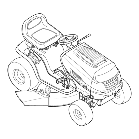
Controls a nd Features PTO (Blade Engage) Lever Drive Pedal Brake Pedal Throttle/Choke Lever ignition Switch Cruise Control Button Shift Lever Deck Lift Lever Cup Holder Figure 4-1 Lawn Tractor controls and features are illustrated in Fig 4-1 and described on the following pages. -
Page 13: Brake Pedal
ThrottleControlLever Ignition Switch Your new lawn tractor will have one of the following ignition The throttle control lever is located on the right side of the switches. Use Fig. 4-3 to identify which switch your machine tractor's dash panel. This lever controls the speed of the engine utilizes and follow these instructions... - Page 14 DrivePedal IMPORTANT: Always set the parking brake when leaving the tractor unattended. The drive pedal is located below the brake pedal CruiseControl Button on the right front side of the tractor along the running board. Depress the drive pedal with The cruise control button is located...
-
Page 15: Operation
If the interlock system should ever malfunction, do not operate the tractor. Contact an authorized MTD service dealer. the tractor in the REVERSE CAUTION MODE. Always look down and behind ARNING: Use extreme before and while backing. - Page 16 Activate the choke by moving the throttle into the choke Rsvsrs8 position. Push Turn the ignition key clockwise to the START position. After Button indicator CH|LDREN AROUND the engine starts, release the key. It will return to the ON Light position.
-
Page 17: Engaging The Blades
way forward into the engaged (ON) position. excess of 15 degrees (a rise of approximately 2-1/2 IMPORTANT: The engine will automatically shut off if the PTO ARNING: Do not mow on inclines with a slope in feet every 10 feet). The tractor could overturn lever is engaged with the shift lever in position for reverse travel. - Page 18 Mulching(ifSo Equipped) Select models come equipped with a mulch kit which incorporates special blades, already standard on the tractor, in a process of recirculating grass clippings repeatedly beneath cutting deck. The ultra-fine clippings are then forced back into the lawn where they act as a natural fertilizer. Observe the following points for the best results when mulching: Never attempt...
-
Page 19: Maintenance And Adjustments
Maintenance& Adjustments Maintenance The engine is equipped with either a twist-and-pull drain port or a tabbed drain port. If your engine has the twist- WARNING: Before performing any maintenance and-pull drain go to step a. If your engine is equipped with the tabbed drain go to step b. -
Page 20: Cleaning The Engineanddeck
FrontAxles Battery Failures Some common causes for battery failure are: Each of the front wheel axles and rims is equipped with a grease fitting. See Fig. 6-2. Lubricate with a No. 2 multi-purpose grease Incorrect initial activation applied with a grease gun after every 25 hours of tractor operation. Overcharging Freezing Undercharging... -
Page 21: Steering Adjustment
FrontToRear The front of the cutting deck is supported by a stabilizer bar that can be adjusted to level the deck from front to rear. The front of the deck should be between 1/4-inch and 3/8-inch lower than the rear of the deck. Adjust if necessary as follows: With the tractor parked on a firm, level surface, place the deck lift lever in the top notch (highest... -
Page 22: Maintenance Schedule
Replace hex nut after the proper adjustment is achieved. ParkingBrakeAdjustment NOTE:Threading the ball joints too far onto the drag links will cause the front tires to "toe-in" too far. Proper toe-in while the engine is running. Always disengage PTO, between 1/16"... -
Page 23: Cutting Deck Removal
Service Note: Note what hole the other end of the belt-keeper rod is Cutting Deck Removal inserted into for reinstallation purposes. To remove the cutting deck, proceed as follows: Remove the belt (C) from around the tractor's engine Place the PTO/Blade Engage lever in the disengaged (OFF) pulley and idler pulley(s). -
Page 24: Cutting Blades
Remove the hex flange nut that secures the blade to the spindle assembly. See Fig. 7-5. To properly sharpen the cutting blades, remove equal amounts of metal from both ends of the blades along the cutting edges, parallel to the trailing edge, at a 25 °- to 30 °... - Page 25 See your authorized MTD service dealer to have the transmission drive Set the tractor's parking brake before removing the jumper belt replaced.
- Page 26 NOTE: Several components must be removed in order to change the tractor's lower deck belt. See an authorized MTD Service All belts on your tractor are subject to wear and should Dealer to have your lower drive belt replaced or phone Customer replaced if any signs of wear are present.
-
Page 27: Troubleshooting
Troubleshooting Problem Cause Remedy Engine fails to start 1. PTO!Blade Engage knob engaged. 1. Place knob in disengaged (OFF) position. 2. Parking brake notengaged. 2. Engage parking brake. 3. Spark plug wire disconnected. 3. Connect wire to spark plug. 4. Throttle control lever not in correct starting 4. -
Page 28: Replacement Parts
Characteristics and features discussed and/or illustrated in this manual may not be applicable to all models. MTD LLC reserves the right to change product specifications, designs and equipment without notice and without incurring obligation. NOTE: Download a complete Parts Manual free of charge at www.mtdproducts.com... -
Page 29: Attachments & Accessories
Attachments & Accessories The following attachments and accessories are compatible for all 600 series lawn tractors. See the retailer from which you purchased your tractor, or call the contact number on page 2, for information regarding price and availability. tiller or mold boa rd plow). Use of this type of eq ui pment Wl LL void the tractor's wa rra nty. -
Page 30: California Emission Control Warranty Statement
CALIFORNIA EMISSION CONTROL WARRANTY STATEMENT YOUR WARRANTY RIGHTS AND OBLIGATIONS The CaliforniaAir ResourcesBoardandMTDConsumerGroupInc are pleasedto explainthe evaporativeemissioncontrolsystemwarrantyon your2008 lawn mower.In California,new lawnmowersmust be designed,built and equippedto meetthe State'sstringentanti-smogstandards.MTDConsumerGroupInc must warrantthe EECSon yourlawn mowerfor the periodof time listed below providedthere has beenno abuse, neglector impropermaintenanceof yourlawn mower. Your EECSmay includeparts such asthe carburetor,fuel-injectionsystem,the ignitionsystem,catalyticconverter,fuel tanks,fuel lines,fuel caps, valves, canisters,filters,vapor hoses,clamps,connectors,andother associatedemission-relatedcomponents. - Page 31 WARRANTED PARTS: The repairor replacementof any warrantedpart otherwiseeligiblefor warrantycoveragemay be excludedfrom such warrantycoverageif MTDConsumerGroup Inc demonstratesthatthe lawn mowerhas been abused,neglected,or improperlymaintained,andthat such abuse,neglect, or impropermaintenancewasthe directcauseof the needfor repairor replacementof the part. That notwithstanding, a ny adjustmentof a componentthat has a factory installed,and properly operating,adjustmentlimitingdevice is still eligiblefor warrantycoverage.
-
Page 32: Limited Warranty
MANUFACTURER'S LiMiTED WARRANTY The limited warranty set forth below is given by MTD LLC with c. Routine maintenance items such as lubricants, filters, blade respect to new merchandise purchased and used in the United States sharpening, tune-ups, brake adjustments, clutch adjustments,...