Table of Contents
Advertisement
Quick Links
Operator-Parts Manual
Manuel de l'opérateur - Manuel de pièces
Manual del operador - Manual de piezas
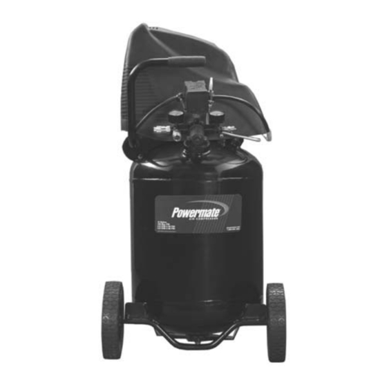
Oilless, Single Stage, Direct Drive, Electric Air Compressor
Sans l'huile, d'un seule étape, à prise directe, compresseur d'air électrique
Sin aciete, de una sola etapa, de mando directo, compresor de aire eléctrico
Product style and configuration may vary.
Le style et la configuration du produit peuvent varier.
El estilo y la configuración del producto puede variar.
Specification Chart________Tableau des spécifications_______Cuadro de especificaciones
MODEL NO.
RUNNING
(MODÈLE)
H.P.
(MODELO)
(CV)
VLP0881203
1.0
WARNING: Read and understand all safety precautions in this manual before operating. Failure to comply with
instructions in this manual could result in personal injury, property damage, and/or voiding of your warranty. The
manufacturer WILL NOT be liable for any damage because of failure to follow these instructions.
AVERTISSEMENT : Lisez et veillez à bien comprendre toutes les consignes de sécurité de ce manuel avant
d'utiliser l'appareil. Toute dérogation aux instructions contenues dans ce manuel peut entraîner l'annulation de la
garantie, causer des blessures et/ou des dégâts matériels. Le fabricant NE SAURA être tenu responsable de dommages
résultant de l'inobservation de ces instructions.
ADVERTENCIA: Lea y comprenda todas las precauciones de seguridad contenidas en este manual antes de
utilizar esta unidad. Si no cumple con las instrucciones de este manual podría ocasionar lesiones personales, daños a la
propiedad y/o la anulación de su garantía. El fabricante NO SERÁ responsable de ningún daño por no acatar estas
instrucciones.
?
Questions? See back page._____Questions ? Consultez la page final._____¿Preguntas? Vea la página final.
TANK CAPACITY
GALLONS
(CAPACITÉ DU
RÉSERVOIR - LITRES)
(CAPACIDAD DEL
TANQUE - LITROS)
12 (45,4)
VOLTAGE/
AMPS/PHASE
PRESSURE
(TENSION/
(PRESSION
AMPS/PHASE)
D'OUVERTURE)
(VOLTAJE
(PRESION DE
AMP/FASE)
CONEXION)
120/14/1
200-2647
KICK-IN
KICK-OUT
PRESSURE
(PRESSION DE
FERM.)
(PRESION DE
DESCONEXION)
95
125
(6,55 bar)
(8,62 bar)
200-2647_ Rev A_4-07
Revision A
Advertisement
Table of Contents

Related Manuals for Powermate 200-2647


Summary of Contents for Powermate 200-2647
- Page 1 Operator-Parts Manual 200-2647 Manuel de l’opérateur - Manuel de pièces Revision A Manual del operador - Manual de piezas Oilless, Single Stage, Direct Drive, Electric Air Compressor Sans l’huile, d’un seule étape, à prise directe, compresseur d’air électrique Sin aciete, de una sola etapa, de mando directo, compresor de aire eléctrico Product style and configuration may vary.
-
Page 2: Table Of Contents
TABLE OF CONTENTS SAFETY GUIDELINES ......3 Checking the Relief Valve ....14 OVERVIEW . -
Page 3: Safety Guidelines
SAFETY GUIDELINES The following information relates to protecting YOUR SAFETY and PREVENTING EQUIPMENT PROBLEMS. To help you recognize this information, we use the following symbols. Please read the manual and pay attention to these sections. – A POTENTIAL HAZARD THAT WILL CAUSE SERIOUS INJURY OR LOSS OF LIFE. DANGER: –... -
Page 4: Consignes De Sécurité
CONSIGNES DE SÉCURITÉ Les informations suivantes concernent VOTRE SÉCURITÉ et LA PROTECTION DU MATÉRIEL CONTRE LES PANNES. Pour vous aider à identifier la nature de ces informations, nous utilisons les symboles suivants. Veuillez lire le manuel et prêter attention à ces sections. –... -
Page 5: Pautas De Seguridad
PAUTAS DE SEGURIDAD La información que sigue se refiere a la protección de SU SEGURIDAD y la PREVENCIÓN DE PROBLEMAS DEL EQUIPO. Como ayuda para reconocer esta información, usamos los siguientes símbolos. Lea por favor el manual y preste atención a estas secciones. PELIGRO: - UN POSIBLE RIESGO QUE CAUSARÁ... -
Page 6: Overview
OVERVIEW \ VUE D’ENSEMBLE \ RESUMEN GENERAL BASIC AIR COMPRESSOR COMPONENTS Fig. 1 Oilless air compressors are factory lubricated for life and do not require any oil. The basic components of the air compressor are the electric motor, pump, pressure switch, and tank. The electric motor (see A) powers the pump. -
Page 7: Assembly
ASSEMBLY / ASSEMBLAGE / MONTAJE limitaciones de tiempo respecto a las reclamaciones por ASSEMBLING THE COMPRESSOR daños. Unpack the air compressor. Inspect the unit for damage. If La caja debe contener los elementos siguientes: the unit has been damaged in transit, contact the carrier •... -
Page 8: Compressor Controls
COMPRESSOR CONTROLS / COMMANDES DU COMPRESSEUR / CONTROLES DEL COMPRESOR Sortie d’air (voir F) COMPRESSOR CONTROLS Raccorder le tuyau pneumatique à cette sortie. ON/OFF Switch (see A) This switch turns on the compressor. It is operated CONTROLES DEL COMPRESOR manually, but when in the ON position, it allows the compressor to start up or shut down automatically, without warning, upon ON/OFF Interruptor (vea A) air demand. -
Page 9: Electrical Power Requirements
ELECTRICAL POWER REQUIREMENTS SPÉCIFICATIONS DE L'ALIMENTATION ÉLECTRIQUE REQUERIMIENTOS DE ALIMENTACIÓN ELÉCTRICA S'il l'utilisation d'une rallonge est inévitable, le cordon ELECTRICAL WIRING électrique ne doit pas dépasser 15 m (50 pi) et doit être d'un Refer to the air compressor’s serial label for the unit’s calibre minimum de 12 (AWG). -
Page 10: Requerimientos De Alimentación Eléctrica
REQUERIMIENTOS DE ALIMENTACION ELECTRICA Figura 1 CABLEADO ELÉCTRICO Caja de tomacorriente Consulte el rótulo del número de serie del compresor de aire puesta a tierra para ver los requerimientos de voltaje y amperaje de la unidad. CORDONES PROLONGADORES Tomacorriente puesta NOTA: Evite el uso de cordones prolongadores. -
Page 11: Operating Instructions
OPERATING INSTRUCTIONS \ MODE D’EMPLOI \ INSTRUCCIONES OPERATIVAS DAILY STARTUP Turn the ON/OFF switch to the OFF position (see A). Close the tank petcock (see D). Turn in the clockwise direction. Plug in the power cord. WARNING: High temperatures are generated by the electric motor and the pump. -
Page 12: Instrucciones Operativas
INSTRUCCIONES OPERATIVAS ARRANQUE DIARIO Coloque el interruptor ON/OFF en la posición OFF (vea A). Cierre la llave de descompresión del tanque (vea D). Hágalo girar hacia la derecha. Enchufe el cordón eléctrico. AVERTENCIA: El motor eléctrico y la bomba producen altas temperaturas. Para evitar quemaduras y otras lesiones, NO toque el compresor durante su funcionamiento. -
Page 13: Maintenance
MAINTENANCE \ ENTRETIEN \ MANTENIMIENTO El mantenimiento regular asegurará una operación sin MAINTENANCE problemas. Su compresor de aire con alimentación eléctrica representa lo mejor en ingeniería y construcción; sin embargo, WARNING: To avoid personal injury, always shut off and aún la maquinaria de mejor calidad requiere un mantenimiento unplug the compressor and relieve all air pressure from periódico. -
Page 14: Checking The Relief Valve
MAINTENANCE \ ENTRETIEN \ MANTENIMIENTO CHECKING THE RELIEF VALVE REVISIÓN DE LA VÁLVULA DE ALIVIO Pull the relief valve daily to ensure that it is operating Tire de la válvula de alivio todos los días para asegurarse de properly and to clear the valve of any possible obstructions. que esté... -
Page 15: Troubleshooting Chart
TROUBLESHOOTING CHART Note: Troubleshooting problems may have similar causes and solutions. PROBLEM POSSIBLE CAUSE SOLUTION Tank petcock is open Low pressure or not Close petcock enough air Check fittings with soapy water. Tighten or reseal leaking fittings. Fittings Leak DO NOT OVERTIGHTEN. Compressor does not Restricted air intake Clean or replace intake filter element. -
Page 16: Dépannage
DÉPANNAGE Remarque : Les problémes de dépannage peuvent avoir des causes et des solutions similaires. PROBLÉME CAUSE POSSIBLE SOLUTION Robinet de réservoir ouvert Fermer le robinet Faible pression ou manque d'air Vérifier les raccords à l'eau savonneuse. Resserrer ou étanchéifier Fuite des raccords les raccords. -
Page 17: Cuadro De Detección De Fallos
CUADRO DE DETECCIÓN DE FALLOS Nota: Los problemas de detección de fallos pueden tener causas y soluciones similares. CAUSA POSIBLE SOLUCION PROBLEMA Presión baja o insuficiente El grifo de desagüe del tanque está Cierre el grifo de desagüe cantidad de aire. abierto o bien Revise las conexiones con agua jabonosa. -
Page 18: Parts Drawing
PARTS DRAWING \ DESSIN DES PIÈCES \ ESQUEMA DE LA PIEZAS 200-2647... -
Page 19: Parts List
PARTS LIST \ LISTE DE PIÈCES \ LISTA DE LAS PIEZAS Item Part No Qté Núm / P Cant Description Description Descripción Tank............Réservoir.........Tanque 072-0006 Petcock ..........Robinet de décompression .....Llave de desagüe 094-0127 Vibration pad........Tampon ...........Almohadilla 033-0008 Hubcap ..........Chapeau de moyeu......Tapacubo 095-0052 Wheel..........Roue..........Rueda 036-0031... -
Page 20: Parts And Service
Powermate Corporation, Aurora, IL 60504 © 2007 Powermate Corporation All Rights Reserved. Tous droits réservés. Reservados todos los derechos. Powermate® is a registered trademark of Powermate Corporation Powermate® est une marque déposée de Powermate Corporation Powermate® es una marca comercial registrada de Powermate Corporation...