Table of Contents
Advertisement
Statement:
This manual is the intellectual property of FOXCONN, Inc. Although the
information in this manual may be changed or modified at any time,
FOXCONN does not obligate itself to inform the user of these changes.
Trademark:
All trademarks are the property of their respective owners.
Version:
User's Manual V1.0 in English for 915PL7AE series motherboard.
P/N: 91-181-915-A5-0E
Symbol description:
Note: refers to important information that can help you to use motherboard
better.
Attention: indicates that it may damage hardware or cause data loss,
and tells you how to avoid such problems.
Warning: means that a potential risk of property damage or physical
injury exists.
More information:
If you want more information about our products, please visit FOXCONN
website: www.foxconnchannel.com
Advertisement
Table of Contents

Related Manuals for Foxconn 915PL7AE series


Summary of Contents for Foxconn 915PL7AE series
-
Page 1: More Information
This manual is the intellectual property of FOXCONN, Inc. Although the information in this manual may be changed or modified at any time, FOXCONN does not obligate itself to inform the user of these changes. Trademark: All trademarks are the property of their respective owners. - Page 2 Item Checklist: Thanks for your purchasing FOXCONN 915PL7AE series motherboard. Please check the package; if there are missing or damaged items, contact your dis- tributor as soon as possible. 915PL7AE Series Motherboard (x1) FOXCONN Utility CD (x1) 915PL7AE User Manual (x1)
-
Page 3: Declaration Of Conformity
Declaration of conformity HON HAI PRECISION INDUSTRY COMPANY LTD 66 , CHUNG SHAN RD., TU-CHENG INDUSTRIAL DISTRICT, TAIPEI HSIEN, TAIWAN, R.O.C. declares that the product Motherboard 915PL7AE is in conformity with (reference to the specification under which conformity is declared in accordance with 89/336 EEC-EMC Directive) EN 55022:1998/A2:2003 Limits and methods of measurements of radio disturbance characteristics of information technology equipment... - Page 4 Declaration of conformity Trade Name: FOXCONN Model Name: 915PL7AE Industry Inc. Responsible Party: Address: 458 E. Lambert Rd. Fullerton, CA 92835 Telephone: 714-738-8868 Facsimile: 714-738-8838 Equipment Classification: FCC Class B Subassembly Type of Product: Motherboard Manufacturer: HON HAI PRECISION INDUSTRY...
-
Page 5: Table Of Contents
Table of Contents Chapter Product Introduction Chapter Installation Instructions Supply .................... Chapter BIOS Description Standard CMOS Features ................31 BIOS Features ................... Advanced BIOS Features ................Advanced Chipset Features ..............Integrated Peripherals ................Power Management Setup ................. PnP/PCI Configurations ................PC Health Status .................. - Page 6 Warning: 1. Attach the CPU and heatsink using silica gel to ensure full contact. 2. It is suggested to select high-quality, certified fans in order to avoid damage to the motherboard and CPU due high temperatures. 3. Never turn on the machine if the CPU fan is not properly installed. 4.
- Page 7 This manual is suitable for motherboard of 915PL7AE series. Each motherboard is carefully designed for the PC user who wants diverse features. with onboard 10/100M LAN with onboard 1G LAN with 6-channel audio with 8-channel audio with 1394 function with SATA function with RAID function You can find PPID label on the motherboard.
- Page 8 Chapter Thank you for buying FOXCONN 915PL7AE series motherboard. This series of motherboard is one of our new products, and offers superior performance, reliability and quality, at a reasonable price. This motherboard adopts the advanced Intel 915PL+ ICH6/ICH6R chipset, providing users ®...
-
Page 9: Chapter 1 Product Introduction
Chapter 1 Product Introduction Main Features Size ATX form factor of 12 inch x 8.6 inch Microprocessor Supports Intel Pentium 4 Prescott, Celeron D processors ® ® Supports FSB at 533MHz/800MHz Supports Hyper-Threading technology Supports FSB Dynamic Bus Inversion (DBI) Chipset Intel 915PL (North Bridge) + ICH6/6R (South Bridge) - Page 10 Supports high quality differential CD input PCI Express x16 Support Supports 4 GB/sec (8 GB/sec concurrent) bandwidth Low power consumption and power management features F.G.E. (Foxconn Graphics Extension) 8X Support Compatible with AGP8X/4X specification Supports Microsoft DirectX 9.0 standard Green Function...
-
Page 11: Product Introduction
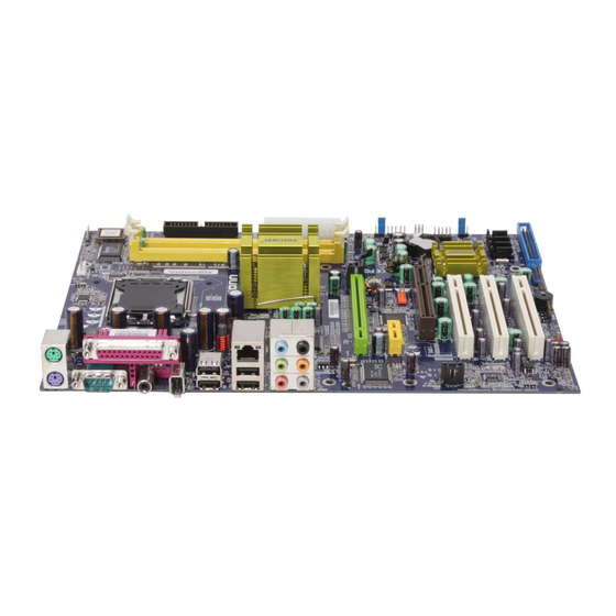
Chapter 1 Product Introduction Expansion Slots Three PCI slots One PCI Express x1 slot One PCI Express x16 graphics slot One F.G.E. slot Advanced Features PCI 2.3 specification compliant Supports Windows 2000/XP soft-off Supports Wake-on-Modem function (optional) Supports PC Health function (capable of monitoring system voltage, CPU/ system temperature, and fan speed) 2005-5-26, 17:34... - Page 12 Chapter 1 Product Introduction Motherboard Layout ATA 100/66/33 Note: The above motherboard layout is provided for reference only; please refer to the physical motherboard. 2005-5-26, 17:34...
- Page 13 Chapter 1 Product Introduction Chapter This chapter introduces the hardware installation process, including the installation of the CPU, memory, power supply, slots, rear panel and pin headers, and the mounting of jumpers. Caution should be exercised during the installation of these modules. Please refer to the motherboard layout prior to any installation and read the contents in this chapter carefully.
-
Page 14: Installation Instructions
Chapter 2 Installation Instructions Attention: Take note of the following precautions before you install components or change settings. 1. Use a grounded wrist strap or touch a safely grounded object, such as an attached power supply, before handling components to avoid damaging them due to static electricity. 2. - Page 15 Chapter 2 Installation Instructions This motherboard supports single Pentium 4 Processor including Prescott, ® Celeron D processor in an LGA775 package. It also supports Hyper-Thread- ing Technology and FSB Dynamic Bus Inversion (DBI). Installation of CPU Load lever Load plate Load cap Lifted tab 2005-5-26, 17:34...
- Page 16 Chapter 2 Installation Instructions Correct Wrong 2005-5-26, 17:34...
- Page 17 Chapter 2 Installation Instructions Warning: Excessive temperatures will severely damage the CPU and system. Therefore, you should install CPU cooling fan and make sure that the cooling fan works normally at all times in order to prevent overheating and damaging to the CPU. Please refer to your CPU fan user guide to install it properly.
- Page 18 Chapter 2 Installation Instructions Qualified CPU Vendor List The following table lists the CPUs that have been tested and qualified for use with this motherboard. Processor Name Clock Speed FSB(MHz) Intel Celeron ® ® 533MHz 3.06G Intel Celeron ® ® 533MHz 2.93G Intel...
- Page 19 Chapter 2 Installation Instructions Memory This motherboard accomodates two 184-pin DDR slots. These slots support 128Mb, 256 Mb, 512 Mb and 1 Gb DDR technologies for x8 and x16 devices. You must install at least one memory bank to ensure normal operation. Qualified DDR Memory Vendor List The following table lists the memory modules that have been tested and qualified for use on this motherboard.
- Page 20 Chapter 2 Installation Instructions Installation of DDR Memory 1. There is only one gap in the middle of the DIMM slot, and the memory module can be fixed in one direction only. Unlock a DIMM slot by pressing the module clips outward. 2.
-
Page 21: Power Supply
Chapter 2 Installation Instructions Power Supply This motherboard uses an ATX power supply. In order to avoid damaging any devices, make sure that they have been installed properly prior to connecting the power supply. 4-pin ATX_12V Power Connector: PWR2 4-pin ATX_12V power connector The ATX power supply connects to PWR2 and provides power to the CPU. -
Page 22: Rear Panel Connectors
Chapter 2 Installation Instructions Rear Panel Connectors This motherboard provides the ports as below: For -6 models (optional) Parallel Port 1394 Port LAN Port (optional) (Printer Port) (optional) Line-in PS/2 Mouse Connector Line-out PS/2 Keyboard Microphone Connector Serial Port SPDIF USB 2.0 Ports (COM1) Coaxial Out... - Page 23 Chapter 2 Installation Instructions 1394 Port (optional) This digital interface supports electronic devices such as digital cameras, scanners, and printers. USB 2.0 Ports These four Universal Serial Bus (USB) ports are available for connecting USB 2.0/1.1 devices. LAN Port (optional) This port allows connection to a Local Area Network (LAN) through a network hub.
-
Page 24: Other Connectors
Chapter 2 Installation Instructions Other Connectors This motherboard includes connectors for floppy devices, IDE devices,serial ATA devices, USB devices, IR module, and others. FDD connector: FLOPPY This motherboard includes a standard FDD connector, supporting 360 K, 720 K, 1.2 M, 1.44 M, and 2.88 M FDDs. HDD connector: PIDE This motherboard includes one Ultra DMA 100/66/33 IDE connector. - Page 25 Chapter 2 Installation Instructions Power LED Connector (PWRLED) Attach the connector to the power LED on the front panel of the case. The Power LED indicates the system’s status. When the system is in S0 status, the LED is on. When the system is in S1 status, the LED is blink; When the system is in S3, S4, S5 status, the LED is off.
- Page 26 Chapter 2 Installation Instructions Wake-Up On Internal Modem (optional): WOM Through this function, the system which is in suspend or soft-off status can be waken up by a ring signal re- +5V _SB ceived from the internal modem. When this function is enabled, make sure an internal modem card which Modem wake up supports this function is used.
- Page 27 Chapter 2 Installation Instructions Front Audio Connector: F_AUDIO For -6 models (optional) The audio connector provides two kinds of audio output choices: the Front Audio, the Rear Audio. Their priority is sequenced from high to low (Front Audio to Rear Audio).
- Page 28 Chapter 2 Installation Instructions out connector is capable of providing digi- tal audio to external speak-ers or compressed AC3 SPDIF_OUT Empty data to an external Dolby digital decoder. Note: The empty pin of SPDIF cable should be aligned to empty pin of S/PDIF out connector. SPDIF_OUT Speaker Connector: SPEAKER The speaker connector is used to connect speaker...
- Page 29 Installation Instructions Expansion Slots This motherboard includes three 32-bit Master PCI bus slots, one PCI Express x1 slot, one PCI Express x16 slot and one F.G.E.(Foxconn Graphics Extension) slot. PCI Slots The expansion card can be installed in the PCI slot. When you install or take out such card, you must make sure that the power plug has been pulled out.
- Page 30 Chapter 2 Installation Instructions PCI Express Slots PCI Express will offer the following design advantages over the PCI and AGP interface: -Compatible with existing PCI drivers and software and Operating Systems. -High Bandwidth per Pin. Low overhead. Low latency. -PCI Express supports a raw bit-rate of 2.5 Gb/s on the data pins. This results in a real bandwidth per pair of 250 MB/s.
- Page 31 Chapter 2 Installation Instructions Qualified PCI Express x16 Graphics Cards Vendor List The following table lists the PCI Express x16 graphics cards that have been tested and qualified for use with this motherboard. Graphics Chip Model Name Memory Vendor RADEON X300SE 128MB RADEON X800SE 128MB...
- Page 32 Chapter 2 Installation Instructions Jumpers The users can change the jumper settings on this motherboard if needed. This section explains how to use the various functions of this motherboard by chang- ing the jumper settings. Users should read the following contents carefully prior to modifying any jumper settings.
- Page 33 Chapter 2 Installation Instructions BIOS TBL Jumper: JP3 The system cannot boot, if the BIOS failed to be flashed BIOS TBL in conventional flash BIOS process. But you will have Disable no such worry when using the BIOS TBL function, which is used to protect BIOS “Top Boot Block”.
- Page 34 Chapter 2 Installation Instructions Starting up for the first time 1. After making all the connections, replace the system case cover. 2. Be sure that all switches are off. 3. Turn on the devices in the following order. Monitor External SCSI devices (starting with the last device on the chain) System power 4.
- Page 35 Appendix Chapter This chapter tells how to change system settings through the BIOS Setup menus. Detailed descriptions of the BIOS parameters are also provided. You have to run the Setup Program when the following cases occur: 1. An error message appears on the screen during the system POST process.
-
Page 36: Chapter Bios Description
Chapter 3 BIOS Description Enter BIOS Setup The BIOS is the communication bridge between hardware and software, correctly setting up the BIOS parameters is critical to maintain optimal system performance. Power on the computer, when the following message briefly appears at the bottom of the screen during the POST (Power On Self Test), press <Del>... - Page 37 Chapter 3 BIOS Description Advanced BIOS Features The advanced system features can be set up through this menu. Advanced Chipset Features The values for the chipset can be changed through this menu, and the system performance can be optimized. Integrated Peripherals Onboard peripherals can be set up through this menu.
-
Page 38: Standard Cmos Features
Chapter 3 BIOS Description Standard CMOS Features This sub-menu is used to set up the standard CMOS features, such as the date, time, HDD model and so on. Use the arrow keys to select the item and set up, and then use the <PgUp> or <PgDn> keys to choose the setting values. Standard CMOS Features Menu Date This option allows you to set the desired date (usually as the current date) - Page 39 Chapter 3 BIOS Description Award (Phoenix) BIOS can support 3 HDD modes: CHS, LBA and Large or read Auto mode. For HDD<528MB For HDD>528MB & supporting LBA (Logical Block Addressing) Large For HDD>528MB but not supporting LBA Auto Recommended mode Drive A/B This option allows you to select the kind of FDD to be installed, including [None], [360K, 5.25 in], [1.2M, 5.25 in], [720K, 3.5 in], [1.44M, 3.5 in] and [2.88 M, 3.5 in].
- Page 40 Chapter 3 BIOS Description Memory This is a Display-Only Category, determined by POST (Power On Self Test) of the BIOS. Base Memory The BIOS POST will determine the amount of base (or conventional) memory installed in the system. Extended Memory The BIOS determines how much extended memory is present during the POST.
-
Page 41: Bios Features
Chapter 3 BIOS Description BIOS Features BIOS Features Menu [SuperBoot] SuperBoot (Default: Disabled) SuperBoot allows system-relevant information to be stored in CMOS upon the first normal start-up of your PC, and the relevant parameters will be restored to help the system start up more quickly on each subsequent start-up. The available setting values are: Disabled and Enabled. - Page 42 Chapter 3 BIOS Description SuperSpeed Menu Auto Detect PCI Clk (Default: Enabled) This option is used to set whether the clock of an unused PCI slot will be disabled to reduce electromagnetic interference. Spread Spectrum (Default: Disabled) If you enable spread spectrum, it can significantly reduce the EMI (Electro- Magnetic Interference) generated by the system.
- Page 43 Chapter 3 BIOS Description CPU Voltage Regulator (Default: Default) The option is used to adjust the CPU voltage. Memory Voltage (Default: Default) This option is used to set memory voltage. System Core Voltage (Default: Default) This option is used to set system core voltage. 3).
-
Page 44: Advanced Bios Features
Chapter 3 BIOS Description Advanced BIOS Features Advanced BIOS Features Menu CPU Feature Press <Enter> to set the items of CPU feature. Please refer to page 39. Hard Disk Boot Priority This option is used to select the priority for HDD startup. After pressing <Enter>, you can select the HDD using the <PageUp>/<PageDn>... - Page 45 Chapter 3 BIOS Description First/Second/Third Boot Device (Default: Floppy/Hard Disk/CDROM) This option allows you to set the boot device sequence. The available setting values are: Floppy, LS120, Hard Disk, CDROM, ZIP100, USB-FDD, USB-ZIP, USB-CDROM, LAN and Disabled. Boot Other Device (Default: Enabled) With this function set to Enabled, the system will boot from some other devices if the first/second/third boot devices failed.
- Page 46 Chapter 3 BIOS Description CPU Feature Menu Delay Prior to Thermal (Default: 16Min) This option is used to set the delay time before the CPU enters auto thermal mode. The setting values are: 4 Min, 8 Min, 16 Min, 32 Min. Thermal Management (Default: Thermal Monitor 1) This option is used to manage Prescott CPU thermal.
-
Page 47: Bios Description
Chapter 3 BIOS Description Advanced Chipset Features Advanced Chipset Features Menu DRAM Timing Selectable (Default: By SPD) This item determines DRAM clock/ timing using SPD or manual configuration. The available setting values are: By SPD and Manual. CAS Latency Time (Default: depend on memory) This item determines CAS Latency. - Page 48 Chapter 3 BIOS Description System BIOS Cacheable (Default: Enabled) Select “Enabled” to allow caching of the system BIOS which may improve performance. If any other program writes to this memory area, a system error may result. The available setting values are: Enabled and Disabled. Video BIOS Cacheable (Default: Disabled) Select “Enabled”...
-
Page 49: Integrated Peripherals
Chapter 3 BIOS Description Integrated Peripherals Integrated Peripherals Menu Use the arrow keys to select your options; press the <Enter> key to enter the setup sub-menu. The options and setting methods are discussed below: Onchip IDE Device Menu On-Chip Primary/Secondary PCI IDE (Default: Enabled) Use this item to enable or disable the Primary/Secondary PCI IDE channel that is integrated on the motherboard. - Page 50 Chapter 3 BIOS Description IDE Primary Master/Slave UDMA (Default: Auto) UltraDMA technology provides faster access to IDE devices. If you install a device that supports UltraDMA, change the appropriate item on this list to Auto. The available setting values are: Disabled and Auto. SATA Mode (Default: IDE) This option is used to set the Serial ATA Mode.
- Page 51 Chapter 3 BIOS Description Onboard Device Menu USB/USB 2.0 Controller (Default: Enabled) This option is used to set whether the USB/USB 2.0 Controller is enabled. The available setting values are: Disabled and Enabled. USB Keyboard/Mouse Support (Default: Disabled) This option is used to set whether the USB keyboard/mouse controller is enabled in a legacy operating system (such as DOS).
- Page 52 Chapter 3 BIOS Description Super IO Device Menu Power on By Mouse (Default: Disabled) This option is used to set the power-on method of your PC. The available setting values are: Disabled, Mouse Move, Mouse Click. Power On By Keyboard (Default: Disabled) This option is used to set the power-on method of your PC.
- Page 53 Chapter 3 BIOS Description Onboard Parallel Port (Default: 378/IRQ7) This item allows you to determine onboard parallel port controller I/O address and interrupt request (IRQ). Setting values include Disabled, 378/IRQ7, 278/ IRQ5, and 3BC/IRQ7. Parallel Port Mode (Default: SPP) Select an address and corresponding interrupt for the onboard parallel port. Setting values include SPP, EPP, ECP, ECP+EPP.
-
Page 54: Power Management Setup
Chapter 3 BIOS Description Power Management Setup Power Management Setup Menu ACPI Function (Default: Enabled) ACPI stands for “Advanced Configuration and Power Interface”. ACPI is a standard that defines power and configuration management interfaces between an operating system and the BIOS. In other words, it is a standard that describes how computer components work together to manage system hardware. - Page 55 Chapter 3 BIOS Description means that after the computer enters power saving mode, only the monitor will close, however, the vertical and horizontal scanning movement of the screen continues. When you select the “V/H SYNC + Blank” mode the vertical and horizontal scanning movement of screen stops when the computer enters power saving mode.
-
Page 56: Pnp/Pci Configurations
Chapter 3 BIOS Description PnP/PCI Configurations PnP/PCI Configurations Menu Init Display First (Default: PCI Slot) This option is used to set which display device will be used first when your PC starts up. The available setting values are: PCI Slot, Onboard. Reset Configuration Data (Default: Disabled) This option is used to set whether the system is permitted to automatically distribute IRQ DMA and I/O addresses when each time the machine is turned... -
Page 57: Pc Health Status
Chapter 3 BIOS Description PC Health Status PC Health Status Menu Shutdown Temperature (Default: Disabled) This option is used to set the system temperature upper limit. When the temperature exceeds the setting value, the motherboard will automatically cut off power to the computer. The setting values are: Disabled, 70 C/158 F, 75 Warning Temperature (Default: Disabled) -
Page 58: Load Fail-Safe Defaults
Chapter 3 BIOS Description Load Fail-Safe Defaults Press <Enter> to select this option. A dialogue box will pop up that allows you to load the default BIOS settings. Select <Y> and then press <Enter> to load the defaults. Select <N> and press <Enter> to exit without loading. The defaults set by BIOS set the basic system functions in order to ensure system stability. -
Page 59: Save & Exit Setup
Chapter 3 BIOS Description If you do not want to set a password, just press <Enter> when prompted to enter a password, and in the screen the following message will appear. If no password is keyed in, any user can enter the system and view/modify the CMOS settings. PASSWORD DISABLED!!! Press any key to continue …... - Page 60 Chapter The utility CD that came with the motherboard contains useful software and several utility drivers that enhance the motherboard features. This chapter includes the following information: Utility CD content Start to install drivers 2005-5-26, 17:35...
-
Page 61: Chapter Driver Cd Introduction
Chapter 4 Driver CD Introduction Utility CD content This motherboard comes with one Utility CD. To begin using the CD, simply insert the CD into your CD-ROM drive. The CD will automatically displays the main menu screen. 1. Install Drivers Using this choice, you can install all the drivers for your motherboard. -
Page 62: Start To Install Drivers
D. Word Perfect Office 12 3. Browse CD Click here to browse CD content. 4. Homepage Click here to visit Foxconn motherboard homepage. Note: 1. Install the latest patch first if your OS is Windows XP or Win- dows 2000.