Table of Contents
Advertisement
Statement:
This manual is the intellectual property of Foxconn, Inc. Although the
information in this manual may be changed or modified at any time,
Foxconn does not obligate itself to inform the user of these changes.
Trademark:
All trademarks are the property of their respective owners.
Version:
User's Manual V1.0 in English for 915M07 series motherboard.
P/N: 91-181-1M7-10-00
Symbol description:
Note: refers to important information that can help you to use motherboard
better.
Attention: indicates that it may damage hardware or cause data loss,
and tells you how to avoid such problems.
Warning: means that a potential risk of property damage or physical
injury exists.
More information:
If you want more information about our products, please visit Foxconn's
website: www.foxconnchannel.com
915M07-English preface.p65
1
2004-6-1, 9:23
Advertisement
Table of Contents

Related Manuals for Foxconn 915M07 series


Summary of Contents for Foxconn 915M07 series
- Page 1 This manual is the intellectual property of Foxconn, Inc. Although the information in this manual may be changed or modified at any time, Foxconn does not obligate itself to inform the user of these changes. Trademark: All trademarks are the property of their respective owners.
- Page 2 Item Checklist: Thank for your purchasing Foxconn’s 915M07 series motherboard. Please check the package; if there are missing or damaged items, contact your distributor as soon as possible. 915M07 series motherboard (x1) Foxconn Utility CD (x1) 915M07 User Manual (x1)
-
Page 3: Declaration Of Conformity
Declaration of conformity HON HAI PRECISION INDUSTRY COMPANY LTD 66 , CHUNG SHAN RD., TU-CHENG INDUSTRIAL DISTRICT, TAIPEI HSIEN, TAIWAN, R.O.C. declares that the product Motherboard 915M07 series is in conformity with (reference to the specification under which conformity is declared in accordance with 89/336 EEC-EMC Directive) EN 55022/A1: 2000 Limits and methods of measurements of radio disturbance... - Page 4 Declaration of conformity Foxconn Trade Name: Model Name: 915M07 Industry Inc. Responsible Party: Address: 458 E. Lambert Rd. Fullerton, CA 92835 Telephone: 714-738-8868 Facsimile: 714-738-8838 Equipment Classification: FCC Class B Subassembly Type of Product: Motherboard Manufacturer: HON HAI PRECISION INDUSTRY...
-
Page 5: Table Of Contents
Table of Contents Product Introduction Chapter Installation Instructions Chapter Supply .................... BIOS Description Chapter Standard CMOS Features ................37 BIOS Features ................... Advanced BIOS Features ................Advanced Chipset Features ..............Integrated Peripherals ................Power Management Setup ................. PnP/PCI Configurations ................PC Health Status .................. - Page 6 Table of Contents Chapter Driver CD Introduction Utility CD content ..................66 Start to Install Drivers ................. 67 Install Chipset Software ................67 Install IAA RAID (optional) ................67 Install DirectX 9.0b ..................68 Install VGA Driver (optional) ............... 68 Install Audio Driver (optional) ..............
- Page 7 Warning: 1. Attach the CPU and heatsink using silica gel to ensure full contact. 2. It is suggested to select high-quality, certified fans in order to avoid damage to the motherboard and CPU due high temperatures. 3. Never turn on the machine if the CPU fan is not properly installed. 4.
- Page 8 This manual is suitable for motherboard of 915M07 series. Each motherboard is carefully designed for the PC user who wants diverse features. with onboard 100M LAN with onbaord 1G LAN with 6 channel audio with 8 channel audio with 1394 with SATA with RAID 2004-6-1, 9:23...
- Page 9 Chapter Thank you for buying Foxconn’s 915M07 series motherboard. This series of motherboard is one of our new products, and offers superior performance, reliability and quality, at a reason- able price. This motherboard adopts the advanced Intel ® 915G/ P/GV+ ICH6/ICH6R chipset, providing users a computer plat- form with a high integration-compatibility-performance price ratio.
-
Page 10: Main Features
Chapter 1 Product Introduction Main Features Size mATX form factor of 9.6 inch x 9.6 inch Microprocessor Supports Intel ® Prescott-T processor in an LGA775 package Supports FSB at 533 MHz/800 MHz Supports Hyper-Threading technology Supports FSB Dynamic Bus Inversion (DBI) Chipset ®... -
Page 11: Chapter Product Introduction
Chapter 1 Product Introduction Onboard 1394 (-E ) (optional) Support hot plug With rate of transmission at 400 Mbps Self-configured addressing Can connect with 2 independent 1394 units synchronously at most Onboard LAN (-L/-K) (optional) Supports 10/100/1000 (-K optional) Mbit/sec Ethernet LAN interface built-in on board Onboard Audio (-6)(optional) AC’97 2.3 Specification Compliant... - Page 12 Chapter 1 Product Introduction Expansion Slots Two PCI slots One PCI Express x1 slot One PCI Express x16 Graphics slot (only for 915G/P) Advanced Features PCI 2.3 specification compliant Supports Windows 2000/XP soft-off Supports Wake-on-LAN, Wake-on modem functions Supports PC Health function (capable of monitoring system voltage, CPU, system temperature, and fan speed) 915M07 Series User Manual...
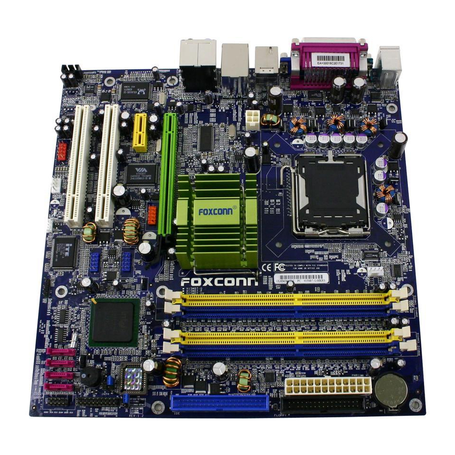
- Page 13 Chapter 1 Product Introduction 915M07 Layout Note: The above motherboard layout is provided for reference only; please refer to the physical motherboard. 915M07 Series User Manual...
-
Page 14: Atx Power Connector
Chapter 1 Product Introduction ATX 12V connector This power connector connects the 4-pin 12 V plug from the ATX 12 V power supply. CPU socket LGA 775 Socket T is for the Intel ® Prescott-T processor. North Bridge controller ® Intel 915G/P/GV supports FSB 800/533 MHz, DDR 333/400 MHz, PCI Express x16 (only for I915G/P). -
Page 15: Serial Ata Connectors
Chapter 1 Product Introduction Serial ATA connectors These four 7-pin connectors accommodate the thin cables for Serial ATA devices. South Bridge Intel ICH6/6R are subsystem that integrate various I/O functions including one channel ATA100 bus master IDE controller, up to eight USB 2.0 ports, four serial ATA 150 , one PCI Express x1, HD audio codec. - Page 16 Chapter 1 Product Introduction PCI Express x1 slot The x1 slot also promises to benefit overall system performance as well, allowing more throughput to cards currently utilizing the PCI interface. With more bandwidth at their disposal, cards such as TV tuners, I/O devices, and other such cards can bring more and better features to the PC.
- Page 17 Chapter 1 Product Introduction Chapter This chapter introduces the hardware installation process, in- cluding the installation of the CPU, memory, power supply, slots, rear panel and pin headers, and the mounting of jumpers. Caution should be exercised during the installation of these modules.
-
Page 18: Chapter Installation Instructions
Chapter 2 Installation Instructions Notes: Take note of the following precautions before you install components or change settings. 1. Use a grounded wrist strap or touch a safely grounded object, such as an attached power supply, before handling components to avoid damaging them due to static electricity. 2. - Page 19 Chapter 2 Installation Instructions ® This motherboard supports single Pentium 4 Processor including Prescott desktop CPUs in an LGA 775 package. It also supports Hyper-Threading Technology and FSB Dynamic Bus Inversion (DBI). Installation of CPU Load lever Load plate Load cap Load stiffener gLoa Lifted tab...
- Page 20 Chapter 2 Installation Instructions Correct Wrong Lift up the lever. Use thumb to open the load plate. Be careful not to touch the contacts. 915M07 Series User Manual...
- Page 21 Chapter 2 Installation Instructions Note : Excessive temperatures will severely damage the CPU and system. Therefore, you should install CPU cooling fan and make sure that the cooling fan works normally at all times in order to prevent overheating and damaging to the CPU. Please refer to your CPU fan user guide to install it properly.
- Page 22 Chapter 2 Installation Instructions Memory This motherboard includes four 184-pin slots with 2.6 V for DDR. These support 256 Mb, 512 Mb and 1 Gb DDR technologies for x8 and x16 devices, and support maximum memory bandwidth of 3.2 GB/s in Single-Channel or Dual-Channel asymmetric mode, or 6.4 GB/s in Dual-Channel interleaved mode, assuming DDR 333/400.
- Page 23 Chapter 2 Installation Instructions Installation of DDR Memory 1. There is only one gap near the center of the DIMM slot, and the memory module can be fixed in one direction only. Unlock a DIMM slot by pressing the module clips outward. 2.
-
Page 24: Power Supply
Chapter 2 Installation Instructions Power Supply This motherboard uses an ATX power supply. In order to avoid damaging any devices, make sure that they have been installed properly prior to connecting the power supply. 4-pin ATX_12 V Power Connector: PWR2 The ATX power supply connects to PWR2 and provides power to the CPU. -
Page 25: Installation Instructions
Chapter 2 Installation Instructions Rear Panel Connectors This motherboard provides the ports as below: For -6 models 1394 Port LAN Port Parallel Port (optional) (Printer Port) Line-in PS/2 Mouse Connector Line-out PS/2 Keyboard Microphone Connector Serial Port USB 2.0 Ports VGA Port (COM1) (only for I915 G/GV) - Page 26 Chapter 2 Installation Instructions VGA Port (only for I915 G/GV) The VGA Port is for output to a VGA-compatible device. 1394 Port (optional) This digital interface supports electronic devices such as digital cameras, scanners, and printers. USB 2.0 Ports These four Universal Serial Bus (USB) ports are available for connecting USB 2.0/1.1 devices.
- Page 27 Chapter 2 Installation Instructions Other Connectors This motherboard includes connectors for FDD, IDE HDD, Serial ATA, USB, IR module, and others. FDD connector: FLOPPY This motherboard includes a standard FDD connector, supporting 360 K, 720 K, 1.2 M, 1.44 M, and 2.88 M FDDs. FDD connector 915M07 Series User Manual...
- Page 28 Chapter 2 Installation Instructions HDD connector: IDE The connector supports the provided Ultra DMA 100/66 IDE hard disk ribbon cable. Connect the cable’s blue connector to the IDE connector, then connect the gray connector to the Ultra DMA 100/66 slave device (hard disk drive) and the black connector to the Ultra DMA 100/66 master device.
- Page 29 Chapter 2 Installation Instructions Front Panel Connector: FP1 This motherboard includes one connector for connecting the front panel switch and LED indicators. P W R B T N # Empty P W R L E D HD-LED R E S E T IDE LED Connector (HD-LED) The connector connects to the case’s IDE indicator LED indicating the activity status of hard disks.
- Page 30 Chapter 2 Installation Instructions IrDA Header: IR This connector supports wireless transmitting and receiving device. Before using this function, configure the settings of IR Mode from the “Integrated Peripherals” section of the CMOS Setup. Empty IRRX IRTX Fan Connectors: CPU_FAN, FAN1 The fan speed of CPU_FAN and FAN1 can be detected and viewed in “PC Health Status”...
- Page 31 Chapter 2 Installation Instructions USB Headers: F_USB1, F_USB2 Besides four USB ports on the rear panel, the series of motherboards also have two 10-pin headers on board which may connect to front panel USB cable (optional) to provide additional four USB ports. Empty 5V_DUAL 5V_DUAL...
- Page 32 Chapter 2 Installation Instructions Audio Connectors: CD_IN, AUX_IN (optional) CD_IN, AUX_IN is Sony standard CD audio connectors, it can be connected to a CD-ROM drive through a CD audio cable. CD_IN CD_L CD_R AUX_IN AUX_R AUX_L 1394 Header: F_1394 (Optional) The 1394 expansion cable can be connected to either the front (provided that the front panel of your chassis is equipped with the appropriate interface) or real panel of the chassis.
- Page 33 Chapter 2 Installation Instructions Wake-Up On LAN: WOL Through the Wake-Up On LAN function, a wake event occurring from the net- work can wake up the system. To utilize this function, please be sure an ATX 12V power supply with a 5VSB line capable of delivering a current of at least 1A, and a LAN adapter which supports this function.
- Page 34 Chapter 2 Installation Instructions Audio Interface: F_AUDIO (for -6 models) The audio interface provides two kinds of audio output choices: the Front Audio, the Rear Audio. Their priority is sequenced from high to low (Front Audio to Rear Audio). If headphones are plugged into the front panel of the chassis (using the Front Audio), then the Line-out (Rear Audio) on the rear panel will not work.
- Page 35 Chapter 2 Installation Instructions out connector is capable of providing digital audio to external speak- ers or compressed AC3 data to an external Dolby digital decoder. SPDIF_OUT Empty 5V_SYS SPDIF_OUT The connectors connect to the chassis security switch on the case. The system can detect the chasis intrusion through the status of this connector.
- Page 36 Chapter 2 Installation Instructions Expansion Slots This motherboard includes two 32-bit Master PCI bus slots, one PCI Express x 1 slot, and one PCI Express x 16 slot (only for 915 G/P). PCI Slots The expansion cards can be installed in the two PCI slots. When you install or take out such cards, you must make sure that the power plug has been pulled out.
- Page 37 Chapter 2 Installation Instructions -Low power consumption and power management features PCI Express will take two forms, x16 and x1 PCI Express slots. Whereas the x16 slot is reserved for graphic/video cards, the x1 slot is designed to accommo- date less bandwidth-intensive cards, such as a modem or LAN card. The difference in bandwidth between the x16 and x1 slots is notable to be sure, with the x16 slot pushing 4GB/sec (8GB/sec concurrent) of bandwidth, and the x1 PCI Express slot offering 250MB/sec.
- Page 38 Chapter 2 Installation Instructions Jumpers The users can change the jumper settings on this motherboard if needed. This section explains how to use the various functions of this motherboard by chang- ing the jumper settings. Users should read the following content carefully prior to modifying any jumper settings.
- Page 39 Chapter 2 Installation Instructions Clear CMOS Jumper: JP3 The motherboard uses the CMOS RAM to store all the set parameters. The CMOS can be cleared by removing the CMOS jumper. How to clear CMOS? 1. Turn off the AC power supply and connect pins 1 and 2 together using the jumper cap.
- Page 40 Chapter 2 Installation Instructions BIOS TBL Jumper: JP2 The system cannot boot if the BIOS fails to be flashed in conventional flash BIOS process. But not to worry when you use the BIOS TBL function. It is used to protect BIOS “Top Boot Block”.
- Page 41 Chapter 2 Installation Instructions Starting up for the first time 1. After making all the connections, replace the system case cover. 2. Be sure that all switches are off. 3. Turn on the devices in the following order. a. Monitor b.
- Page 42 Chapter This chapter tells how to change system settings through the BIOS Setup menus. Detailed descriptions of the BIOS pa- rameters are also provided. You have to run the Setup Program when the following cases occur: 1. An error message appears on the screen during the system T-- This page is intentionally left blank --his POST process.
-
Page 43: Chapter Bios Description
Chapter 3 BIOS Description Enter BIOS Setup The BIOS is the communication bridge between hardware and software, correctly setting up the BIOS parameters is critical to maintain optimal system performance. Power on the computer, when the following message briefly appears at the bottom of the screen during the POST (Power On Self Test), press <Del>... - Page 44 Chapter 3 BIOS Description Advanced BIOS Features The advanced system features can be set up through this menu. Advanced Chipset Features The values for the chipset can be changed through this menu, and the sys- tem performance can be optimized. Integrated Peripherals Onboard peripherals can be set up through this menu.
-
Page 45: Standard Cmos Features
Chapter 3 BIOS Description Standard CMOS Features This sub-menu is used to set up the standard CMOS features, such as the date, time, HDD model and so on. Use the arrow keys select the item to set up, and then use the <PgUp> or <PgDn> keys to choose the setting values. Standard CMOS Features Menu Date This option allows you to set the desired date (usually as the current date) - Page 46 Chapter 3 BIOS Description Award (Phoenix) BIOS can support 3 HDD modes: CHS, LBA and Large or Auto mode. For HDD<528MB For HDD>528MB & supporting LBA (Logical Block Addressing) Large For HDD>528MB but not supporting LBA Auto Recommended mode Drive A/B This option allows you to select the kind of FDD to be installed, including “None”, [360K, 5.25 in], [1.2M, 5.25 in], [720K, 3.5 in], [1.44M, 3.5 in] and [2.88 M, 3.5 in].
- Page 47 Chapter 3 BIOS Description Memory This is a Display-Only Category, determined by POST (Power On Self Test) of the BIOS. Base Memory The BIOS POST will determine the amount of base (or conventional) memory installed in the system. Extended Memory The BIOS determines how much extended memory is present during the POST.
-
Page 48: Bios Features
Chapter 3 BIOS Description BIOS Features BIOS Features Menu [SuperBoot] SuperBoot (Default: Disabled) SuperBoot allows system-relevant information to be stored in CMOS upon the first normal startup of your PC, and the relevant parameters will be restored to help the system start up more quickly on each subsequent startup. The avail- able setting values are: Disabled and Enabled. - Page 49 Chapter 3 BIOS Description SuperSpeed Menu System Memory Frequency (Default: Auto) This option is used to set system memory frequency. CPU Clock Ratio (Default: Depend on CPU ) This option is used to set the ratio of an unlocked CPU. Auto Detect PCI Clk (Default: Enabled) This option is used to set whether the clock of an unused PCI slot will be disabled to reduce electromagnetic interference.
-
Page 50: Advanced Bios Features
Chapter 3 BIOS Description Advanced BIOS Features Advanced BIOS Features Menu CPU Feature Press <Enter> to set the items of CPU feature. Please refer to page 45. Hard Disk Boot Priority This option is used to select the priority for HDD startup. After pressing <Enter>, you can select the HDD using the <PageUp>/<PageDn>... - Page 51 Chapter 3 BIOS Description Hyper-Threading Technology (Default: Enabled) This option is used to turn on or off the Hyper-Threading function of the CPU. The available setting values are: Disabled and Enabled. Note: This function will not be displayed until a CPU that supports Hyper- Threading has been installed.
- Page 52 Chapter 3 BIOS Description Gate A20 Option (Default: Fast) This option is used to set up the A20 signal control necessary for access to the 1MB memory. The available setting values are: Normal and Fast. Typematic Rate (Chars/Sec) (Default: 6) Use this item to define how many characters per second a held-down key generated.
- Page 53 Chapter 3 BIOS Description CPU Feature Menu Delay Prior to Thermal (Default: 16Min) This option is used to set the delay time before the CPU enters auto thermal mode. The setting values are: 4 Min, 8 Min, 16 Min, 32 Min. Thermal Management (Default: Thermal Monitor 1) This option is used to manage Prescott CPU thermal.
-
Page 54: Advanced Chipset Features
Chapter 3 BIOS Description Advanced Chipset Features Advanced Chipset Features Menu DRAM Timing Selectable (Default: By SPD) This item determines DRAM clock/ timing using SPD or manual configuration. The available setting values are: By SPD and Manual. CAS Latency Time (Default: Depend on memory) This item determines CAS Latency. - Page 55 Chapter 3 BIOS Description Memory Hole At 15M-16M (Default: Disabled) This option is used to determine whether the 15M-16M address field of memory is reserved for the ISA expansion card. The available setting values are: En- abled and Disbled. PCI Express Root Port Func Press <Enter>...
- Page 56 Chapter 3 BIOS Description PCI Express Root Port Func Menu PCI Express Port 1/ 2/ 3/ 4 (Default: Auto) This option is used to enable or disabled PCI Express port 1/2/3/4. The avail- able setting values are: Auto, Enabled, Disabled. PCI-E Compliancy Mode (Default: v1.0a) This option is used to select the PCI Express compliancy mode version.
-
Page 57: Integrated Peripherals
Chapter 3 BIOS Description Integrated Peripherals Integrated Peripherals Menu Use the arrow keys to select your options; press the <Enter> key to enter the setup sub-menu. The options and setting methods are discussed below: Onchip IDE Menu IDE HDD Block Mode (Default: Enabled) This option is used to set whether the IDE HDD block mode is allowed. - Page 58 Chapter 3 BIOS Description IDE Primary/Secondary Master/Slave PIO (Default: Auto) These two items let you assign which kind of PIO (Programmed Input/Output) is used by IDE devices. Choose Auto to let the system auto detect which PIO mode is best or select a PIO mode from 0-4. IDE Primary/Secondary Master/Slave UDMA (Default: Auto) UltraDMA technology provides faster access to IDE devices.
- Page 59 Chapter 3 BIOS Description Onboard Device Menu USB Controller (Default: Enabled) This option is used to set whether the USB Controller is enabled. The avail- able setting values are: Disabled and Enabled. USB 2.0 Controller (Default: Enabled) This option is used to set whether the USB 2.0 Controller is enabled. The available setting values are: Disabled and Enabled.
- Page 60 Chapter 3 BIOS Description Onboard Lan Controller (Default: Enabled) This option is used to set whether the onboard LAN controller is enabled. The available setting values are: Disabled and Enabled. Onboard Lan Boot ROM (Default: Disabled) This option is used to decide whether to invoke the boot ROM of the onboard LAN chip.
- Page 61 Chapter 3 BIOS Description SuperIO Device Menu Onboard FDC Controller (Default: Enabled) This option is used to set whether the onboard FDC controller is enabled. The available setting values are: Disabled and Enabled. Onboard Serial Port 1/2 (Default: 3F8/IRQ4 / 2F8/IRQ3) This option is used to assign the I/O address and interrupt request (IRQ) for the onboard serial port 1/2.
-
Page 62: Power Management Setup
Chapter 3 BIOS Description Power Management Setup Power Management Setup Menu PCI Express PM Function Press <Enter> to set the item of PCI Express PM function. Please refer to page 57. Note: This option is applicable when PC x 1 Lan card has been installed to PCI Express x 1 slot. - Page 63 Chapter 3 BIOS Description Power Management (Default: User Define) This option is used to set the power management scheme. Available setting values are: User Define, Min Saving, and Max Saving. Vdieo Off Method (Default: DPMS) This option is used to define the video off method. “Blank Screen” mode means that after the computer enters power saving mode, only the monitor will close, however, the vertical and horizontal scanning movement of the screen continues.
- Page 64 Chapter 3 BIOS Description PWRON After PWR-Fail (Default: Off) This option is used to set what action the PC will take with the power supply when it resumes after a sudden power failure.The available options are: Off (remain in turn off status),On (auto power on) and Former-Sts (resume with the previous status).
- Page 65 Chapter 3 BIOS Description PCI Express PM Function Menu PCI Express PME (Default: Enabled) This item is used to enable or disable PCI Express PME. The setting values are Disabled and Enabled. Power Management Events Menu Wake up by PCI card (Default: Enabled) This option is used to set the system to wake up by PCI card.
- Page 66 Chapter 3 BIOS Description Wake up On LAN (Default: Enabled) This option is used to set the system to wake up on Lan. The setting values are: Disabled and Enabled. USB KB /MS WakeUp From S3 (Default: Disabled) This option is used to set the system to wake up by USB equipment when it is in S3 (Suspend to RAM) mode.
-
Page 67: Pnp/Pci Configurations
Chapter 3 BIOS Description PnP/PCI Configurations PnP/PCI Configurations Menu Reset Configuration Data (Default: Disabled) This option is used to set whether the system is permitted to automatically distribute IRQ DMA and I/O addresses when each time the machine is turned on. -
Page 68: Pc Health Status
Chapter 3 BIOS Description PC Health Status PC Health Status menu Shutdown Temperature (Default: Disabled) This option is used to set the system temperature upper limit. When the temperature exceeds the setting value, the motherboard will automatically cut off power to the computer. The setting values are Disabled and 60 C/140 C/149 F, 70... - Page 69 Chapter 3 BIOS Description System Fan Speed The current speed of the system fan will be automatically detected by the system. Smart Fan Controller(Default: Disabled) (optional) This option is used to enable or disable smart fan function. The setting values are Disabled and Enabled.
-
Page 70: Frequency/Voltage Control
Chapter 3 BIOS Description Frequency/Voltage Control Frequency/Voltage Control Menu System Memory Frequency (Default: Auto) This is used to set system memory frequency. CPU Clock Ratio (Default: Depend on CPU ) This option is used to set the ratio of an unlocked CPU. Auto Detect PCI Clk (Default: Enabled) This option is used to set whether the clock of an unused PCI slot will be disabled to reduce electromagnetic interference. -
Page 71: Load Fail-Safe Defaults
Chapter 3 BIOS Description Load Fail-Safe Defaults Press <Enter> to select this option. A dialogue box will pop up that allows you to load the default BIOS settings. Select <Y> and then press <Enter> to load the defaults. Select <N> and press <Enter> to exit without loading. The defaults set by BIOS set the basic system functions in order to ensure system stability. -
Page 72: Save & Exit Setup
Chapter 3 BIOS Description If you do not want to set a password, just press <Enter> when prompted to enter a password, and in the screen the following message will appear. If no password is keyed in, any user can enter the system and view/modify the CMOS settings. PASSWORD DISABLED!!! Press any key to continue …... - Page 73 Chapter The utility CD that came with the motherboard contains use- ful software and several utility drivers that enhance the motherboard features. This chapter includes the following information: Utility CD content Start to Install drivers Install Chipset Software Install IAA RAID (optional) Install DirectX 9.0b Install VGA Driver (optional) Install Audio Driver (optional)
-
Page 74: Chapter Driver Cd Introduction
C. Norton Internet Security 2004 3. Browse CD Click here to browse CD content. 4. HomePage Click here to visit Foxconn motherboard homepage. Note: 1. Install the latest patch first if your OS is Windows XP or Win- dows 2000. -
Page 75: Start To Install Drivers
Chapter 4 Driver CD Introduction Start to Install Drivers Select <Install Driver>, and click to enter the install driver screen. You can select the driver that you want to install and begin the setup steps. Note: The following setup steps are based on Windows XP environment. -
Page 76: Install Directx 9.0B
Chapter 4 Driver CD Introduction Install DirectX 9.0b Click <Install Driver> from the main menu and enter the install driver menu (as shown in fig. 1). Click <DirectX 9.0b> to start the installation. Click here Install VGA Driver (optional) Click <Install Driver> from the main menu and enter the install driver menu (as shown in fig. -
Page 77: Install Audio Driver (Optional)
Chapter 4 Driver CD Introduction Install Audio Driver (optional) Click <Install Driver> from the main menu and enter the install driver menu (as shown in fig. 1). Click <Audio Driver> to start the installation. Click here Install LAN Driver (optional) Click <Install Driver>... -
Page 78: Install Superutility
Chapter 4 Driver CD Introduction Install SuperUtilily From the main menu, select <Accessories> (as shown in following fig. 1). Click <SuperUtilily> to start the setup. Click here Install Adobe Reader From the main menu, select <Accessories> (as shown in following fig. 1). Click <Adobe Reader>... -
Page 79: Install Norton Internet Security 2004
Chapter 4 Driver CD Introduction Install Norton Internet Security 2004 From the main menu, select <Accessories> as shown in following fig. 1. Click <Norton Internet Security 2004> to start the setup. Click here 915M07 Series User Manual... - Page 80 Chapter 4 Driver CD Introduction Chapter This chapter will introduce how to use attached software. This chapter provides the following information: SuperStep SuperLogo SuperUpdate 915M07 Series User Manual...
-
Page 81: Chapter Directions For Bundled Software
4. Simple and easy to operate, with a user-friendly graphics interface. Using SuperStep: System Fan1 Go to Fan speed page CPU Fan Link to Foxconn website speed Exit Program Minimize Window Adjust CPU SuperStep Help Fan warning criteria About SuperStep... - Page 82 Chapter 5 Directions for Bundled Software Adjust voltage warning criteria (upper limit) Go to Voltage page Current voltage readings Reset the warning Apply the Adjust voltage criteria to default warning criteria adjustments settings (lower limit) Go to Temperature page Current CPU Adjust CPU tem- perature warning temperature...
- Page 83 Chapter 5 Directions for Bundled Software Go to Clock page Current CPU Clock Current PCI Clock Adjust the Adjust the CPU FSB CPU Ratio Reset to the default Apply the adjustments settings Go to Alarm page Check for the system to automatically provide warning message...
-
Page 84: Superlogo
The best resolution is 136x84 for top-right logo and 640x480 or 800x600 for full screen logo. Using SuperLogo: Go to ROM Info page Display the Flash Information Link to Foxconn website Exit Program Minimize Window SuperLogo Help About SuperLogo... - Page 85 Chapter 5 Directions for Bundled Software Go to Change Logo page Full screen mode Top-Right mode Follow the Wiz- Boot without logo ard to complete the logo update Go to Update BIOS page Browse a BIN file BIOS image file for updating BIOS location Follow the Wizard...
-
Page 86: Superupdate
3. Simple and easy to operate, with a user-friendly graphics interface. Using SuperUpdate: Perform the BIOS update Browse BIOS bin from local image file from local HDD Link to Foxconn website Exit Program Minimize Window SuperUpdate Help About SuperUpdate Upgrading BIOS via... - Page 87 Chapter 5 Directions for Bundled Software Backup BIOS to local image: 1. Click <Backup> to backup current BIOS file. 2. Click <OK> to finish the backup process. Update BIOS from local image: 1. Click <Load> to load a new BIOS file. 915M07 Series User Manual...
- Page 88 Chapter 5 Directions for Bundled Software 2. Click <Update>, the following message will appear. 3. Click <Yes> to backup the current BIOS, then the following picture will appear. 4. Click <OK >, then click <Update>. 915M07 Series User Manual...
- Page 89 Chapter 5 Directions for Bundled Software 5. Now is updating. 6. Click <Restart >. 915M07 Series User Manual...
- Page 90 Chapter 5 Directions for Bundled Software Update BIOS On-line: 1. Click <Liveupdate> to automatically update the BIOS from the internet. 2. The following procedure is the same as Upd ate BIOS fro m lo cal imag e. 915M07 Series User Manual...
-
Page 91: Chapter Special Bios Functions
Chapter 6 Special BIOS Functions Chapter This chapter will introduce special functions of BIOS and how to use them in detail. It can further exert the max potential of motherboard to bring you super-value enjoyment. This chapter introduces the following special functions of BIOS: SuperBIOS-Protect SuperBoot SuperRecovery... -
Page 92: Superboot
Chapter 6 Special BIOS Functions SuperBoot SuperBoot technology greatly reduces the long boot process time of computers. A BIOS without SuperBoot has to perform many routines every time when the system starts, such as checking the system core and initializing system peripherals. -
Page 93: Superbios-Protect
Chapter 6 Special BIOS Functions SuperBIOS-Protect The BIOS of the motherboard is contained inside the Flash ROM. Severe viruses, such as the CIH virus, are so dangerous that they may overwrite the BIOS. If the BIOS has been damaged, the system will be unable to boot. We provide the following solution which protects the system BIOS from being attacked by such viruses. -
Page 94: Superrecovery
Chapter 6 Special BIOS Functions SuperRecovery SuperRecovery is an easy-to-operate tool for backing up or recovering your hard disk data. It offers simplified user interfaces with hotkey access and allows you to experience unprecedented high security and reliability with extra functions, such as hotkey launch, and powerful anti-virus protection. - Page 95 Chapter 6 Special BIOS Functions Hard Disk Selection: T he hard disk selection menu will be displayed after you press the hotkey, listing all the IDE HDDs installed in your system. You can switch the highlight bar to make a selection and press <Enter> to confirm it. Attention: 1.
-
Page 96: Main Menu
Chapter 6 Special BIOS Functions Main Menu: Select a HDD to enter main menu. There are five function items, “Divide Hidden Partition”, “Release Hidden Partition”, “Backup”, “Recovery” and “Change Password”. You can switch the highlight bar to make a selection on the opera- tion which should be performed on the HDD and confirm your selection by pressing <Enter>. - Page 97 Chapter 6 Special BIOS Functions Attention : 1. All the HDD data will be cleared by the partitioning process, so it is better to do the division on an empty HDD. 2. At the same time, the overall HDD capacity will decrease in order to make space for the hidden partition, which will become unavailable for normal use.
- Page 98 Chapter 6 Special BIOS Functions Backup: Select BACKUP to enter the Backup interface, where you can find the following three sub-function items: “BACKUP CMOS SETUP”, “BACKUP PARTITION TABLE” and “BACKUP HARDDISK DATA”. Switch the highlight bar by pressing the arrow keys to make a selection and then press <Enter>...
- Page 99 Chapter 6 Special BIOS Functions 3. Backup Harddisk Data: A. If there are active partitions (system partition), you can choose to backup an active partition or the whole disk. But only one can be taken between the two choices. Old data will be replaced by the newly backed up data. B.
- Page 100 Chapter 6 Special BIOS Functions C. A report with all the critical data on this operation will be displayed after the backup is completed. Original Size: The data size loaded in selected partition; Valid Size: The size of valid data. Elapsed T ime: How long the procession cost.
- Page 101 Chapter 6 Special BIOS Functions 1. Recover CMOS Setup: This function is used to restore the latest backup of CMOS settings you made. 2. Recover Partition Table: This function is used to recover all partition tables including extended partitions. 915M07 Series User Manual...
- Page 102 Chapter 6 Special BIOS Functions 3. Recover Hard disk Data: This item is used to restore the backed up data from the hidden partition. 4. Back to Main: T his item is used to exit the Recovery interface. CHANGE PASSWORD Introduction: Select CHANGE PASSWORD to enter the Change Password interface.
-
Page 103: Superspeed
Chapter 6 Special BIOS Functions SuperSpeed SuperSpeed is a powerful and efficient easy technology for PC DIY fans. It offers a friendly interface. Users can set the CPU Clock easily in the BIOS setup. Procedures: Correctly install your CPU. Plug in other configurations and restore the system. Switch on power to the system and press the <Del>... -
Page 104: Appendix
Appendix Using 8-channel Audio (optional) 1. Introduction 8-channel audio is the highest surround sound standard available adding two speakers over existing 6-channel (5.1) audio set-ups. 8-channel surround sound is already a standard feature for premium consumer audio devices, so it only makes sense that as users increasingly use their PCs to listen to the latest multimedia content that 8-channel support makes the migration as a standard PC feature. - Page 105 Chapter 6 Special BIOS Functions Blue Black Green Orange Grey STEP 2. You need to install the driver for the audio chip before you can use the 8- channel audio function. Click here 915M07 Series User Manual...
- Page 106 Appendix STEP 3. After installation of the audio driver, you’ll find an icon on the taskbar’s s status area. Double click the icon, you will see the following picture. STEP 4. Click “Speaker configuration”. The following picture will appear. 915M07 Series User Manual...