Table of Contents
Advertisement
Advertisement
Table of Contents

Related Manuals for Exmark TURF TRACER X-SERIES


Summary of Contents for Exmark TURF TRACER X-SERIES
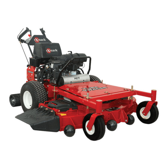
- Page 1 TURF TRACER ® X-SERIES For Serial Nos. 920,000 & Higher Part No. 4500-699 Rev. A...
- Page 2 Replacements may be ordered through the engine manufacturer. Exmark reserves the right to make changes or add improvements to its products at any time without incurring any obligation to make such changes to products manufactured previously.
-
Page 3: Introduction
All Exmark parts are thoroughly tested and inspected before leaving the factory, however, attention is required on your part if you are to obtain the fullest measure of satisfaction and performance. -
Page 4: Table Of Contents
Contents Tracking Adjustment ........35 Hydro Pump Spring Tension Setting ....35 Electric Clutch Adjustment......35 Introduction ............3 Troubleshooting ........... 36 Safety ..............5 Schematics ............38 Safety Alert Symbol ......... 5 Safe Operating Practices ........5 Safety and Instructional Decals ..... 10 Specifications ............ -
Page 5: Safety
The owner is responsible for training the users. Institute in effect at the time of production. • Never let children or untrained people operate Exmark designed and tested this lawn mower to offer or service the equipment. Local regulations may reasonably safe service; however, failure to comply restrict the age of the operator. - Page 6 Safety DANGER DANGER In certain conditions gasoline is extremely In certain conditions during fueling, static flammable and vapors are explosive. electricity can be released causing a spark which can ignite gasoline vapors. A fire or A fire or explosion from gasoline can burn explosion from gasoline can burn you and you, others, and cause property damage.
- Page 7 Safety Operation damage and make repairs before restarting and operating the mower). WARNING – Before clearing blockages. Operating engine parts, especially the muffler, – Whenever you leave the mower. become extremely hot. Severe burns can occur • Stop engine, wait for all moving parts to stop, and on contact and debris, such as leaves, grass, engage parking brake: brush, etc.
-
Page 8: Maintenance And Storage
Safety • Keep engine and engine area free from DANGER accumulation of grass, leaves, excessive grease Operating on wet grass or steep slopes can or oil, and other debris which can accumulate cause sliding and loss of control. Loss of control in these areas. - Page 9 Failure to use original Exmark parts could cause serious injury or death. Replace all parts including, but not limited to, tires, belts, and blades with original Exmark...
-
Page 10: Safety And Instructional Decals
Exmark equipment dealer or labels. distributor or from Exmark Mfg. Co. Inc. • Replace all worn, damaged, or missing safety • Safety signs may be affixed by peeling off the signs. - Page 11 Safety 103–2242 103-2432 116-0404 103–2243 103-4935...
- Page 12 Safety 116-4296 EFI Units Only 1. Fast 2. Slow 117–2718...
-
Page 13: Specifications
Kohler P/N 24 050 13 efficiency Parker wheel drive motors. – Kawasaki: • Hydraulic Oil: Use Exmark Premium Hydro Oil. Kawasaki P/N 49019-7005 • Hydraulic Oil Capacity: 2.4 qt. (2.2 L) – Kohler EFI: •... -
Page 14: Dimensions
Specifications Dimensions Tires & Wheels Drive Front Caster Overall Width: Pneumatic Semi- (Air-Filled) Pneumatic 52 inch Deck 60 inch Deck Quantity Deflector Up 53.4 inches 61.4 inches (135.6 cm) (156.0 cm) Turf Master Smooth Tread Deflector Down 64.8 inches 73.0 inches Size 18 x 8.50-8 11 x 4.00-5... -
Page 15: Torque Requirements
Product Overview Torque Requirements Product Overview Bolt Location Torque Cutter Housing Spindle 140–145 ft-lb (190–197 N-m) Blade Mounting Bolt 55-60 ft-lb (75-81 N-m) (lubricate with anti-seize) 30-35 ft-lb (41-47 N-m) Engine Deck/Mower Deck Support Mount Bolts Anti-Scalp Roller Nyloc 30-35 ft-lb (41-47 N-m) Nut See Figure 9 Anti-Scalp Roller Whizlock 30-35 ft-lb (41-47 N-m) -
Page 16: Operation
Operation Operation as shown in Figure 4, and the drive levers are released, the drive wheels are engaged in the forward direction. Note: Determine the left and right sides of the Squeezing the left hand and/or right hand lever machine from the normal operating position. causes the left hand and/or right hand drive wheel respectively to slow down, stop, or reverse, depending on how far each drive lever is “squeezed”. -
Page 17: Pre-Start
Operation Drive Wheel Release Valves The brake lever engages the park brake on the drive wheels. Located on the left rear corner of the hydrostatic Pull the lever up and rearward to engage the brake. pumps. Push the lever forward and down to disengage the Drive wheel release valves are used to release the brake. -
Page 18: Operating Instructions
Operation Engaging the PTO than 10% ethanol, premium gasoline, or white gas because the fuel system could be damaged. DANGER Do Not add oil to gasoline. The rotating blades under the mower deck are Do Not overfill fuel tank. Fill the fuel tank to the dangerous. -
Page 19: Driving The Machine
Operation 8. Remove the key to prevent children or other unauthorized persons from starting engine. 9. Close the fuel shut-off valve when the machine will not be in use for a few days, when transporting, or when the unit is parked inside a building. -
Page 20: Adjusting The Cutting Height
Operation Driving in Reverse To move rearward in a straight line, squeeze drive levers into the reverse position. To turn left or right, squeeze the right hand drive lever to turn left and the left hand drive lever to turn right. To make a “zero turn”, squeeze either the left hand or the right hand drive lever back into the reverse position while the opposite drive lever is in a forward... - Page 21 Operation Figure 8 For cutting heights above 3.5 inches (90 mm) use the bottom hole. The rollers will still be effective against scalping. 1. Anti-scalp roller 2. Cutting height Figure 7 mounting bracket Left Hand Side Shown For Maximum Deck Flotation, place the rollers one hole position lower.
-
Page 22: Transporting
Operation Transporting Transporting a Unit WARNING Loading the mower onto a trailer without strong enough or properly supported ramps could be dangerous. The ramps could collapse causing the unit to fall, which could cause injury. • Use proper ramps that are secured to the truck or trailer. -
Page 23: Maintenance
Maintenance Maintenance Note: Determine the left and right sides of the machine from the normal operating position. WARNING WARNING While maintenance or adjustments are being The engine can become very hot. Touching a hot made, someone could start the engine. engine can cause severe burns. -
Page 24: Periodic Maintenance
ECU (Electronic Control 4. If the oil level is low, wipe off the area around the Unit). oil fill cap, remove cap and fill to the “FULL” mark on the dipstick. Exmark 4-Cycle Premium Percent Voltage Maximum Charging Engine Oil is recommended;... -
Page 25: Check Mower Blades
Maintenance not touch and that both electrical systems are CAUTION off and at the same rated system voltage. These Corrosion or loose connections can cause instructions are for negative ground systems only. unwanted electrical voltage spikes at anytime 3. Connect the positive (+) cable to the positive (+) during the jump starting procedure. -
Page 26: Check Safety Interlock System
55-60 ft-lb (75-81 N-m). Note: If machine does not pass any of these tests, do not operate. Contact your authorized EXMARK SERVICE DEALER. Important: It is essential that operator safety mechanisms be connected and in proper... -
Page 27: Check For Loose Hardware
2. Clean area around hydraulic reservoir cap and additional information.) remove cap. Oil level should be to the top of the Every 500 hours— baffle inside the tank. If not, add oil. Use Exmark Replace the secondary Premium Hydro Oil. Replace hydraulic reservoir air cleaner element. (May cap and tighten until snug. -
Page 28: Check Condition Of Belts
Maintenance Note: Do Not add any type of tire liner or foam * See step 3 for special lubrication instructions on fill material to the tires. Excessive loads created by the front caster pivots and the Lubricate Caster foam filled tires may cause failures to the hydro drive Wheel Hubs section for special lubrication system, frame, and other components. -
Page 29: Remove Engine Shrouds And Clean Cooling Fins
7. Insert one bearing, one new seal into the wheel. reinstalled. Operating the engine without cooling shrouds will cause engine damage due to Note: Seals (Exmark P/N 103-0063) must be overheating. replaced. 8. If the axle assembly has had both spacer nuts... -
Page 30: Change Hydraulic System Filter
Mobil 1 15W50) jacks for support. Use adequate jack stands or equivalent support. Note: Use only Exmark Part No. 109-4180 for Summer use above 32°F (0°C) or P/N 1-523541 for 7. If either drive wheel does not rotate, one or both Winter use below 32°F (0°C) (Refer to Transmission... -
Page 31: Replace Emissions Air Intake Filter
Maintenance a steady flow of oil to flow out from under the housing. Retighten the capscrews. Do this for both pumps. Note: Hydraulic reservoir can be pressurized up to 5 psi to speed this process. 6. If either drive wheel still does not rotate, stop and repeat steps 4 and 5 above for the respective pump. -
Page 32: Thread Locking Adhesives
Maintenance Torque the slotted nut to 140-155 ft-lb (190-210 • Electric clutch retaining bolt. N-m). • Pump drive idler pivot bolt. Note: Do Not use anti-seize on wheel hub. • Thumb latch screw threads on handles. • Style B (yellow zinc): •... -
Page 33: Adjustments
Maintenance Adjustments Adjust the threaded yoke at the bottom of the speed control linkage (see Figure 17) until the Note: Disengage PTO, shut off engine, wait for tabs are positioned correctly. all moving parts to stop, engage parking brake, and remove key before servicing, cleaning, or making any adjustments to the unit. -
Page 34: Adjust Hydro Control Linkages
Maintenance Note: The neutral lock latches should be “unlocked” and in the forward position. 2. Loosen the front nut on left hydro control linkage as shown in Figure 18. Turn the rear control linkage adjusting nut counterclockwise until wheel rotates forward. Turn the rear nut of left control linkage clockwise 1/4 of a turn at a time, stopping to move the speed control forward and back to neutral, until left wheel... -
Page 35: Tracking Adjustment
Maintenance to neutral. Recheck the drive wheel rotation 2. Check the drive tire pressures and tire to see if further adjustment is necessary. circumferences as stated in Check the Tire Pressures section in Maintenance. 4. The spring that keeps tension on the knob should normally not need adjustment. -
Page 36: Troubleshooting
Troubleshooting Troubleshooting Important: It is essential that all operator safety mechanisms be connected and in proper operating condition prior to mower use. When a problem occurs, do not overlook the simple causes. For example: starting problems could be caused by an empty fuel tank. The following table lists some of the common causes of trouble. - Page 37 Troubleshooting Problem Possible Cause Corrective Action Engine overheats 1. Engine load is excessive 1. Reduce the ground speed. 2. Oil level in the crankcase is low. 2. Add oil to the crankcase. 3. Cooling fins and air passages for the 3.
-
Page 38: Schematics
Schematics Schematics Electrical Diagram-All units except Kohler EFI... - Page 39 Schematics Electrical Diagram-Kohler EFI...
- Page 40 Schematics Electrical Logic Schematic-All units except Kohler EFI...
- Page 41 Schematics Electrical Logic Schematic-Kohler EFI...
- Page 42 Schematics Hydraulic Diagram...
- Page 43 No Claim of breach of warranty shall be cause for cancellation or rescission of the contract of sale of any Exmark mower. All warranty work must be performed by an authorized Exmark Service Dealer using Exmark approved replacement All implied warranties of merchantability (that the parts.
- Page 44 Notes:...
-
Page 45: Service Record
Service Record Date: Description of Work Done: Service Done By:... - Page 47 Figure 22 This page may be copied for personal use. 1. The maximum slope you can safely operate the machine on is 20 degrees. Use the slope indicator to determine the degree of slope of hills before operating. Do Not operate this machine on a slope greater than 20 degrees. Fold along the appropriate line to match the recommended slope.
- Page 48 SEE EXMARK’S COMPLETE LINE OF ACCESSORIES AND OPTIONS MID-MOUNT RIDING ACCESSORIES AND OPTIONS CUSTOM RIDE SEAT SUSPENSION SYSTEM OPERATOR CONTROLLED DISCHARGE FULL SUSPENSION SEAT ROLL OVER PROTECTION SYSTEM (ROPS) DECK LIFT ASSIST KIT SUN SHADE HITCH KIT TRASH CONTAINER LIGHT KIT...