
Related Manuals for Toro TimeCutter Z5020 74372


Summary of Contents for Toro TimeCutter Z5020 74372
- Page 1 Form No. 3358-277 Rev C TimeCutter ® Z5020 Riding Mower Model No. 74372—Serial No. 270000001 and Up Register at www.Toro.com. Original Instructions (EN)
-
Page 2: Introduction
This manual uses two other words to highlight information. Important calls attention to special You may contact Toro directly at www.Toro.com for mechanical information and Note emphasizes general product and accessory information, help finding a information worthy of special attention. -
Page 3: Table Of Contents
Cleaning and Storage .......... 39 Safety ................4 Troubleshooting............40 Safe Operating Practices ........4 Schematics ..............42 Toro Riding Mower Safety ........6 Slope Chart ............7 Safety and Instructional Decals ......8 Product Overview ............11 Controls ............. 12 Operation.............. -
Page 4: Safety
Safety • Never leave a running machine unattended. Always turn off blades, set parking brake, stop engine, and remove key before dismounting. This machine meets or exceeds the B71.1-2003 • Turn off blades when not mowing. Stop the engine specifications of the American National Standards Institute, in effect at the time of production. - Page 5 Service • Avoid sudden starts when mowing uphill because the mower may tip backwards. Safe Handling of Gasoline: • Be aware that loss of traction may occur going To avoid personal injury or property damage, use extra downhill. Weight transfer to the front wheels may care when handling gasoline and other fuels.
-
Page 6: Toro Riding Mower Safety
• Maintain or replace safety and instruction decals as necessary. • Use only genuine Toro replacement parts to ensure that original standards are maintained. Toro Riding Mower Safety The following list contains safety information specific to Toro products or other safety information that you must know that is not included in the ANSI standards. -
Page 7: Slope Chart
Slope Chart... -
Page 8: Safety And Instructional Decals
Safety and Instructional Decals Safety decals and instructions are easily visible to the operator and are located near any area of potential danger. Replace any decal that is damaged or lost. 114-1606 1. Entanglement hazard, belt—keep all guards in place. 106-8717 1. - Page 9 112-9751 1. Parking brake 4. Neutral 2. Fast 5. Reverse 3. Slow 112-9802 1. Height-of-cut 112-9840 1. Read the Operator’s 3. Remove the ignition key Manual. and read the instructions before servicing or performing maintenance. 2. Height of cut 110-6654 1.
- Page 10 Battery Symbols Some or all of these symbols are on your battery 1. Explosion hazard 6. Keep bystanders a safe distance from the battery. 2. No fire, open flame, or 7. Wear eye protection; smoking. explosive gases can cause blindness and other injuries 3.
-
Page 11: Product Overview
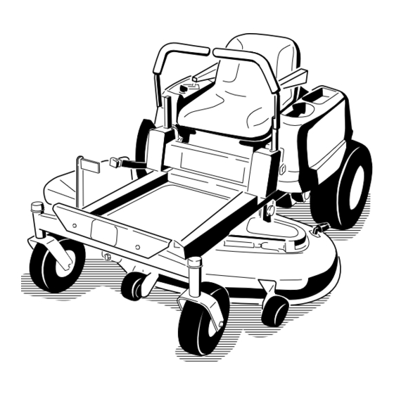
Product Overview Figure 3 7. Front caster wheel 1. Operator seat 4. Height of cut lever 10. Washout fitting 2. Control levers 5. Footrest 8. Rear drive wheel 6. Mower deck 9. Anti-scalp roller 3. Control panel Figure 4 1. Motion control levers 3. -
Page 12: Controls
Controls or backward turns the wheel on the same side forward or in reverse; wheel speed is proportional to the amount Become familiar with all of the controls in Figure 3, the lever is moved. Moving the control levers outward Figure 4, and Figure 5 before you start the engine and from the center position engages the parking brake and operate the machine. -
Page 13: Operation
Recommended Gasoline Operation Use UNLEADED Regular Gasoline suitable for Note: Determine the left and right sides of the automotive use (87 pump octane minimum). Leaded machine from the normal operating position. regular gasoline may be used if unleaded regular is not available. -
Page 14: Filling The Fuel Tank
Add the correct amount of gas stabilizer/conditioner to the gas. In certain conditions during fueling, static Note: A fuel stabilizer/conditioner is most effective electricity can be released causing a spark when mixed with fresh gasoline. To minimize the which can ignite the gasoline vapors. A fire chance of varnish deposits in the fuel system, use fuel or explosion from gasoline can burn you and stabilizer at all times. -
Page 15: Checking The Engine Oil Level
3. Pull up on the Choke control before starting a cold engine (Figure 10). Note: A warm or hot engine may not require choking. G005302 G005183 Figure 7 1. Gas tank body 3. Fill to here, approximately 2. Gas tank neck 4. -
Page 16: Operating The Blades
G005185 Figure 11 1. Control panel 2. Blade control switch—On position G005184 Figure 10 Disengaging the Blades 1. Control panel 5. Run 2. Ignition key—run position 6. Start Push the blade control switch to Off to disengage the 3. Ignition key—start position 7. Choke control blades (Figure 12). -
Page 17: The Safety Interlock System
The Safety Interlock System Driving Forward or Backward The throttle control regulates the engine speed as measured in rpm (revolutions per minute). Place the throttle control in the Fast position for best If safety interlock switches are disconnected performance. Always operate in the full throttle or damaged the machine could operate position. -
Page 18: Stopping The Machine
Adjusting the Height of Cut To turn, release pressure on the motion control lever toward the direction you want to turn (Figure 13). 1. Enter the operator’s position. Place a foot on the The farther you move the motion control levers in foot assist pedal and apply pressure. -
Page 19: Positioning The Seat
Adjusting the Motion Control Levers 4-1/2 in (1 15 mm) 4-1/2 in (1 15 mm) Adjusting the Height 4 in. (102 mm) 4 in (102 mm) The motion control levers can be adjusted higher or 3-1/2 in (89 mm) 3-1/2 in (89 mm) lower for maximum operator comfort. -
Page 20: Side Discharge
To Push the Machine 1. Park the machine on a level surface and disengage the blade control switch. Without the grass deflector, discharge cover, or complete grass catcher assembly mounted 2. Move the motion control levers outward to park in place, you and others are exposed to blade position, stop the engine, remove the key, and wait contact and thrown debris. -
Page 21: Cutting Speed
If enhances decomposition and fertilization. a blade is damaged or worn, replace it immediately with a genuine Toro replacement blade. Mow at Correct Intervals Normally, mow every four days. But remember, grass grows at different rates at different times. -
Page 22: Maintenance
Maintenance Note: Determine the left and right sides of the machine from the normal operating position. Recommended Maintenance Schedule(s) Maintenance Service Maintenance Procedure Interval • Check the safety interlock system. • Check the air cleaner for dirty, loose or damaged parts. •... -
Page 23: Premaintenance Procedures
Premaintenance Lubrication Procedures Greasing the Bearings Raising the Seat Service Interval: Every 25 hours—Grease all lubrication points. Make sure the motion control levers are locked in the Grease Type: No. 2 General Purpose Lithium Base park position. Lift the seat forward and lower it to the Grease floor board. -
Page 24: Engine Maintenance
Engine Maintenance 4. Connect a grease gun to each fitting (Figure 20 and Figure 21). Pump grease into the fittings until grease begins to ooze out of the bearings. Servicing the Air Cleaner 5. Wipe up any excess grease. Service Interval: Before each use or daily—Check the air cleaner for dirty, loose or damaged parts. -
Page 25: Servicing The Engine Oil
carefully; do not use if the sealing surfaces are bent or damaged. 4. Clean the air cleaner base as required and check condition. 5. Install the paper element onto the air cleaner base. Secure with the latch. 6. Close the air cleaner cover door. Servicing the Engine Oil Oil Type: Detergent oil (API service SG, SH, SJ, or higher) - Page 26 2. Park the machine so that the drain side is slightly lower than the opposite side to assure the oil drains completely. 3. Disengage the blade control switch and move the motion controls outward to the park position. 4. Stop the engine, remove the key, and wait for all moving parts to stop before leaving the operating position.
-
Page 27: Servicing The Spark Plug
Type: Champion XC12YC (or equivalent) Air Gap: 0.030 inch (0.76 mm) Removing the Spark Plug 1. Disengage the blade control switch, move the motion controls outward to the park position, stop the engine, and remove the key. 2. Before removing the spark plug(s), clean the area around the base of the plug to keep dirt and debris out of the engine. -
Page 28: Cleaning The Blower Housing
Fuel System Maintenance In certain conditions, gasoline is extremely flammable and highly explosive. A fire or explosion from gasoline can burn you and Figure 28 others and can damage property. 1. Center electrode insulator 3. Air gap (not to scale) •... -
Page 29: Electrical System Maintenance
Electrical System Maintenance Warning CALIFORNIA Proposition 65 Warning Battery posts, terminals, and related accessories contain lead and lead compounds, chemicals known to the State of California to cause cancer and reproductive harm. G005071 Wash hands after handling. Charging the Battery Figure 29 1. -
Page 30: Servicing The Fuses
Incorrect battery cable routing could damage the machine and cables causing sparks. Sparks can cause the battery gasses to explode, resulting in personal injury. • Always disconnect the negative (black) battery cable before disconnecting the positive (red) cable. Figure 31 •... -
Page 31: Drive System Maintenance
Drive System Maintenance Checking the Tire Pressure Service Interval: Every 25 hours—Check tire pressure. Maintain the air pressure in the front and rear tires as G005073 specified. Uneven tire pressure can cause uneven cut. Check the pressure at the valve stem (Figure 33). Check the tires when they are cold to get the most accurate pressure reading. -
Page 32: Mower Maintenance
File down any nicks and sharpen the Checking for Bent Blades blades as necessary. If a blade is damaged or worn, replace it immediately with a genuine Toro replacement 1. Rotate the blades until the ends face forward and blade. For convenient sharpening and replacement, you backward (Figure 35). -
Page 33: Leveling The Mower From Side-To-Side
The blades must be replaced if a solid object is hit, if the blade is out of balance, or the blade is bent. To ensure optimum performance and continued Figure 38 safety conformance of the machine, use genuine Toro 1. Blade 2. Balancer replacement blades. Replacement blades made by other manufacturers may result in non-conformance with safety standards. -
Page 34: Adjusting The Front-To-Rear Blade Slope
G005278 Figure 39 1. Blades side to side 3. Outside cutting edges 2. Sail area of bladè 4. Measure here 6. Measure between the outside cutting edges and G005074 the flat surface (Figure 39). If both measurements are not within 3/16 inch (5 mm), an adjustment is required;... -
Page 35: Removing The Mower
6. Measure from the tip of the front blade to the flat is 1/16-5/16 inch (1.6-7.9 mm) lower than the rear surface and the tip of the rear blade to the flat blade tip (Figure 41). surface (Figure 41). If the front blade tip is not 10. -
Page 36: Mower Belt Maintenance
The spring is under tension when installed and can cause personal injury. Be careful when removing the belt. G005077 Figure 44 1. Mower deck 3. Rear lift rod 2. Hanger bracket G005191 6. Slide the mower rearward to remove the mower belt Figure 45 from the engine pulley. -
Page 37: Replacing The Grass Deflector
Replacing the Grass Deflector An uncovered discharge opening could allow the lawn mower to throw objects in the operator’s or bystander’s direction and result in serious injury. Also, contact with the blade could occur. Never operate the lawn mower unless you install a cover plate, a mulch plate, or a grass chute and catcher. - Page 38 Cleaning Note: If the mower is not clean after one washing, soak it and let it stand for 30 minutes. Then repeat the process. Washing the Underside of the 8. Run the mower again for one to three minutes to Mower remove excess water.
- Page 39 Storage Dispose of fuel properly. Recycle as per local codes. Important: Do not store stabilizer/conditioned Cleaning and Storage gasoline over 30 days. 11. Remove the spark plug(s) and check its condition; 1. Disengage the blade control switch, move the refer to Servicing the Spark Plug in Engine motion controls outward to the park position, stop Maintenance , page 24.
- Page 40 Troubleshooting Problem Possible Cause Corrective Action The engine overheats. 1. The engine load is excessive. 1. Reduce ground speed. 2. The oil level in the crankcase is low. 2. Add oil to the crankcase. 3. The cooling fins and air passages 3.
- Page 41 Problem Possible Cause Corrective Action There is abnormal vibration. 1. The engine mounting bolts are loose. 1. Tighten the engine mounting bolts. 2. The engine pulley, idler pulley, or blade 2. Tighten the appropriate pulley. pulley is loose. 3. The engine pulley is damaged. 3.
- Page 42 Schematics Electrical Diagram (Rev. A)
- Page 43 You are responsible for presenting your equipment to an Authorized Service Dealer as soon as the problem exists. The warranty repairs should be completed in a reasonable amount of time, not to exceed 30 days. If you have a question regarding your warranty coverage, you should contact The Toro® Company at 1-952–948–4027 or call us toll free at the number listed in your Toro Warranty statement.
-
Page 44: The Toro Total Coverage Guarantee
(Dealer) to obtain guarantee policies for your country, province, or state. If for any reason you are dissatised with your Distributor’s service or have difculty obtaining guarantee information, contact the Toro importer. If all other remedies fail, you may contact us at Toro Warranty Company.