Table of Contents
Advertisement
Available languages
Available languages
Advertisement
Table of Contents

Related Manuals for Craftsman 536.886122


Summary of Contents for Craftsman 536.886122
- Page 1 I::RRF rSM FIN 5 Horsepower 22 inch Dual Stage 120V, Electric Start SNOWTHROWER MODEL NO= 536.886122 Caution: Readand follow all Safety Rules and Operating Instructionsbefore first use of this product. SEARS, ROEBUCK AND CO., Hoffman Estates 60179 U.S.A. 760015 08102/96...
- Page 2 SNOW THROWER For two years from the date of purchase, when this Craftsman Snow Thrower is main- tained, lubricated, and tuned up according to the operating and maintenance instruc- tions in the owner's manual, Sears will repair, free of charge, any defect in material or workmanship°...
- Page 3 garments,Wear footwear that will the spark plug, disconnect the cord on improve footing on slippery surfaces. electric motors, thoroughly inspect the snow thrower for any damage, Handle fuel with care; it is highly repair the damage before restarting fl_immable. and operating the snow thrower. (a) Use an approved fuel container.
- Page 4 electric start kits, etc.)° WARNING; The engine exhaust 19. Never operate the snow thrower from this product contains chemicals known to the State of California to cause "without good visibility or light. Always be sure of your footing, and keep a firm cancer, birth defects or other reproductive tlarm.
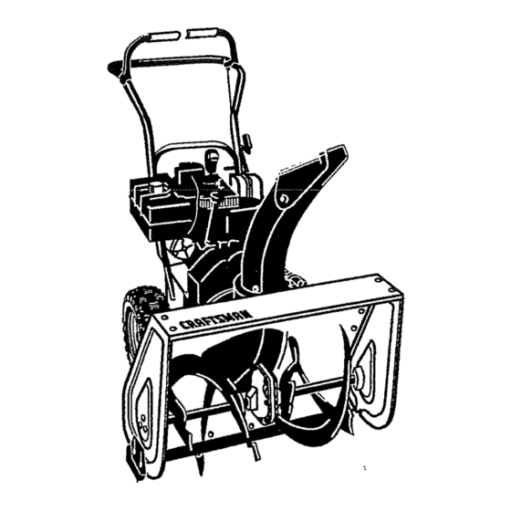
- Page 5 Parts packed separately in carton (not shown full size) 2 - Ignition Keys (Attached to engine in plastic bag) 1 - container 5W30 oil 1 - Snow Chute Assembly The figure below shows the snow thrower CAUTION: Always wear safety completely assembled.
- Page 6 TO REMOVE SNOW THROWER Reinstall flatwasher and adapter. Install eye bolt through lower hole in the left FROM CARTON hand side of the handle. See figure be- = Locate and remove container of 5W30 oil. low. = Locate all parts packed separately and Install the 3/8"...
- Page 7 TO INSTALL SHIFTER LEVER KNOB TO ASSEMBLE SNOW CHUTE Thread the hex nut found in the parts bag • Turn crank assembly counterclockwise onto shifter lever. Thread the shifter lever until it stops. knob onto the threaded end of the shifter •...
- Page 8 4" CHECKLIST Flatwasher Locknut Before you operate your new snow thrower, to ensure that you receive the best performance and satisfaction from this quality product, please review the following checklist: All assembly instructions have been completed. Chute The discharge chute rotates freely. Snow Chute Flange No remaining loose parts in carton, except for extra shear bolt assembly...
- Page 9 KNOW YOUR SNOW THROWER READTHIS OWNER'SMANUALAND SAFETYRULESBEFOREOPERATING",(OUR SNOWTHROWER.Comparethe illustrations with yeurSNOWTHROWER to familiarize yourself with the location of various controls and adjustments. Save this manual for future reference. Choke Off Primer Engine Engine Fast Slow Stop Fuel Start Button Ignition Key insert to run Drive Clutch Auger Clutch...
- Page 10 TO MOVE FORWARD AND The operation of any snow thrower can re- sult in foreign objects being thrown into the BACKWARD eyes, which can result in severe eye dam- • To shift, release the traction drive lever age. Always wear safety glasses or eye and move the speed shifter lever to the shields while operating the snow thrower.
- Page 11 For extreme cold operating conditions of TO USE WHEEL LOCKOUT O°F and below, use a partial synthetic • -The left hand wheel is secured to the axle OW30 motor oil for easier starting. with a klick pin see figure below. This unit NOTE: S.A.E.
- Page 12 Alwaysfill fuel tank outdoorsand usea fun- on the engine first, then plug the other end nel or spoutto preventspilling. into the three-hole grounded receptacle. Makesure to wipe up any spilledfuel before When disconnecting power cord, always startingthe engine. unplug the end in the three-hole grounded receptacle first.
- Page 13 COLD START tf the starter still fails to turn engine, repeat the two previous steps until the starter • . Be sure the auger drive and traction drive gages. Then continue with the directions for levers are in the disengaged (released) cold start.
- Page 14 • After the snow throwing job has been snow blowing is accomplished when the completed, allow the engine to idle for a snow is removed immediately after it few minutes, which will melt snow and fails. accumulated ice off the engine. For complete snow removal, slightly over-,...
- Page 15 GENERAL RECOMMENDATIONS SNOW THROWER The-warranty on this snow thrower does not LUBRICATION - EVERY 25 HOURS cmier items that have been subjected to op- erator abuse or negligence_ To receive full Lubricate Disc Drive Plate eve ry twenty-five value from the warranty, the operator must (25) hours and atthe end of the season and/ maintain the snow thrower as instructed in or before storage.
- Page 16 LU BRICATION - BEFORE STORAGE OIL RECOMMENDATION Remove both wheels, grease (any auto- Only use high quality detergent oil rated motive type grease) both axles (see fig- with API service classification SG, Select ure below) and replace wheels. Do this at the oil's viscosity grade according to your least once a year and/or prior to storage.
- Page 17 • Loosen the carriage bolts and nuts secur- CAUTION; Always disconnect ing the scraper bar to the auger housing. spark plug wire and tie back away from Adjust the scraper bar to the proper posi _ the plug before making any adjustments tion.
- Page 18 AUGER DRIVE BELT if your snow thrower will not discharge " Cable spririg snow, and the auger drive belt (see figure below) is damaged, replace it as follows: Traction Auger Drive Belt Drive Pulley Pulley Traction Locknut Drive Belt Guide (Left Hand) (Right Hand) Traction...
-
Page 19: Traction Drive Belt
° Check clutch control cable adjustment, Drive Pulley 3/32 Inch Belt Guide see page 17. Belt Guide (Left Hand) • Reconnect spark plug wire. 3/32 Inch TRACTION DRIVE BELT If your snow thrower will not move forward, check the traction drive belt (see second figure on page 18) for wear (Check other causes also in the Trouble Shooting Points section). - Page 20 If adjustment is necessary: Remove right side bearing plate. Leave hex shaft in original position. • Loosen bolts in speed selector lever (see figure below). Remove friction wheel from hub. Slip fric- Speed SelectorLever tion wheel off hex shaft towards right side. See figure below.
- Page 21 TO ADJUST CARBURETOR IMPORTANT: Never tamper with the en- gine governor; which is factory set for The carburetor (see figure below) has been proper engine speed. Overspeeding pre-set at the factory and readjustment engine above the factory high speed setting should not be necessary.
- Page 22 = If you do not want to remove gasoline, Z_CAUTION: Never store your snow fuel stabilizer (such as Craftsman Fuel thrower indoors or in an enclosed, poorly Stabilizer No. 33500) may be added to ventilated area if gasoline remains in the any gasoline left in the tank to minimize tank.
-
Page 23: Troubleshooting
CORRECTION TROUBLE " CAUSE Replace defective plug Difficult starting Defective spark plug Use carburetor bowl drain to Water or dirt in fuel system flush and refill with fresh fuel Engtne runs er- Blocked fuel line or low on fuel Clean fuel line; check fuel sup- ply;... -
Page 24: Electric Start Assembly
CRAFTSMAN 22" - 5H.P. snow THROWER 536.886122 ELECTRIC START ASSEMBLY PART NO. PART NAME 33o783 M0toi:,Electric Starter 6216 Screw, 114-20x.50 Screw #6-32x2.50 6217 6219 Cord, Starter Motor Owner's Manual Eng/Sp 760015 319051B ENGINE ASSEMBLY L,t_. ENGINE MOUNTS TO FRONT HOLES... - Page 25 CRAFTSMAN22"- 5H.P.SNOWTHROWER536.886122 FRAME ASSEMBLY 339392(3 REF. REF° PART NO. PART NAME PART NO. PART NAME i i,,15 41529 340578-854 318-16 Hxctdkjam Frame Assembly !133 313854 35497 Spring, Tension Return Screw, 5/16-18x.50 Tap. ! 14o 579872 Idler Arm Traction Lever, 583031-830 Panel, Bottom !141 310169...
- Page 26 CRAFTSMAN 22" - 5H+P. SNOW THROWER 536.886122 DRIVE ASSEMBLY 313995 I REF, REF.I PART NO. PART NAME PART NAME 'N0, PART NO. 579941 Lever, Shaft Tract. Clutch 35497 Screw, 5/i6-18x150 Tap+ 313853 Bearing, Flanged 120638 Washer, Hvsptlk 137185 Cotter Pin +125xl +00 579858 Washer, Sp.
- Page 27 CRAFTSMAN 22" - 5H.P. SNOW THROWER 536.886122 GEAR CASE ASSEMBLY ......,j,, ,,j,, , REF, REF. PART NO, PART NAME ..PART NO. PART NAME ,,,,H,i 10577 Gear Case, RH 431787 Key, Woodruff #61 10576 Gear Case, LH 50221 Bearfng, Flanged 180020 Screw, 1/4-20x.75...
- Page 28 CRAFTSMAN 22" - 5H. P. SNOW THROWER 536.886122 AUGER HOUSING ASSEMBLY 500 IS A WELDMENT AND INCLUDES TWO SIDE PANELS ;3,39972C 'REF PART NO. PART NAME PART NO. PART NAME NO___L. S ta4 ..Pulley, V4L 9524 Screw, 114+20xl+75 577400 Screw 5!16-18x.63...
- Page 29 CRAFTSMAN 22" - 5H.P. SNOW THROWER 536.886122 DISCHARGE CHUTE ASS EMBLY 337160D REF. REF. PART NO. PART NAME PART NO. PART NAME cart....70993 Bolt 5/16-18xo75 S00-1 585501 Lower Chute 12021 Washer, Plastic 500-2 11780 Upper Chute 71038 Nut, 5116-18 hexnylon...
- Page 30 CRAFTSMAN 22"- 5H.P. SNOW THROWER 536.886122 HANDLE ASSEMBLY 339622B ....iREFI PART NO. PART NAME NO. I PART NO. PART NAME 744 I 9552-830 1673 Upper Ha.nd{e Spring, Auger Clutch 745 i 1502 11234 Screw, 5/16-18x2_75 Nut, 1/4-20 Reghexctdk 746 I 120393 Flatwasher ._344x,69x_065...
- Page 31 CRAFTSMAN 22" - 5H.P. SNOW THROWER 536.886122 WHEEL ASSEMBLY 318542E REF. REF. PART NO. PART NAME PART NO. PART NAME 6731585591 580883 Shaft, Axle Wheel/mid Bushing, Wheel 4"Lg 6-52 583012 Sprkt & Hub Assy. Tire & Rim 675 ! 318504...
- Page 32 CRAFTSMAN 22"- 5H.P. SNOW THROWER 536.886122 CHUTE CONTROL ROD ASSEMBLY • 334215C !REF.! iR EF.I N0.1 PART NO. PART NAM E PART NO. PART NAME 309344 865 I 585426 Adapter, Boot to Hanclle t850 Crank Assy, W/yoke ;854 !866 i 120394 Flatwasher .406x31x.065...
- Page 33 CRAFTSMAN 4-CYCLE ENGINE MODEL NUMBER: 143.975001 307/O _A" 170, 365, 384,, 370C 184/<_ 93p,/_/ 287 390 370K ,370G...
- Page 34 CRAFTSMAN 4-CYCLE ENGINE MODEL NUMBER: 143.975001 Psrt No, Part No. Description Description _g'O ..... VaJveSpring 36469A Cylinder (lncl 2;20.72,125) 31673 Valve SpringCap 26727 Dowel Pin Valve CoverGasket 27234A 30968 oil Draln Extension 27666 BreatherBody 30969 Extension Cap BreatherElement 31410 28277...
- Page 35 CRAFTSMAN 4-CYCLE ENGINE MODEL NUMBER: 143.975001 Starter No. 590707 REF_ PART PART NAME NO.,,!,, NO. R_oiI sta_er ..1590707 1590599A spring Pin (Incl. 4) 159o6oo Washer Retainer 1590696 159o6o1 Washer 1590697 Brake Spring J590698 Starter Dog ! 7. 1590699 Dog_Spring I B _"...
- Page 36 CRAFTSMAN 4-CYCLE ENGINE MODEL NUMBER: 143.975001 Carburetor No.632107A REF:I P I REF. PART PART,NAME O. J NO, PART NAME 632107A Carburetor (ind 184 on engine) ..1632019 !Float ..631615 Throttle Shaft & Lever Ass'y. 1631028 ! Float Bowl "O" Ring...
- Page 37 CRAFTSMAN 4-CYCLE ENGINE MODEL NUMBER: 143.975001 Starter Motor No. 33290D REF. PART PART NAME 33290Di Electric Sta_er (110 Volt) 31749 Retainer Ring 33522 Spring Retainer 33769 Anti-drift Spring 33524 Nut and Gear 35911 Thrust Washer 35461 Drive End Cap Assy (Incl 7) 35450 "O"...
- Page 38 CRAFTSMAN Durante dos aSos a partir de la fecha de compra, cuando esta Rernovedora de nieve Craftsman sea manten[dad, lubricada y afinada de acuaredo con las instrucc[ones en el manual del propietario, SEARS reparar_., sin recargo alguno, cualquier defecto en...
- Page 39 cambie a neutro antes de arrancar el 2. Prestare la massima attenzione motor. quando si carica o scarlca la machina quando viene usato un rimorchio o un 3. Nb opere la removedora de nieve sin camion per il trasporto. vestir las prendas de !nvierno adecuadas para ambJentes exteriores.
- Page 40 huecos de ventanas, sitios de cargaJ Siempre refi6rase alas instrucciones manual del operador para consulta descarga, y similares sin el ajuste los detalles importantes si la -aproplado del &ngulo de descarga de la removedora de nteve set& almacenada reeve. Mantenga niSos y mascotas durante un periodo...
- Page 41 Contenido de la bolsa con las partes, mostradas del ta_o real a menos que se indique 1 - Manuel del Propietario(no muestran) 2 - Una bolsa{no muestran) • Piezas no necesarias para el montaje *2- Espacio de reuesto *2 - Tuerca hexagonal 1/4-20 *2-Pernos de seguropo[ esfuerzo col"ante de repuesto (1/4 20 x 1,,-3/4...
- Page 42 PARA RETIRAR LA REMOVEDORA PRECAUCION: Siempre use galas DE NIEVE DE LA CAJA protectoras o protectores para los ojos cuando monte ta removedora de nieve. , Localice y retire el contenedor de aceite de motor 5W30. HERRAMIENTAS REQUERIDAS , Localice el conjunto del cigL_eSaly canal PARA EL MONTAJE de nieve y col6quel o a un lado.
- Page 43 NOTA: Aseg(=rese de que los cables - Cuidadosamente remueva la clavija hendida, el pasador de horquilla y el queden enreda.dos entre las manijas pasador pefforado del extremo de la superior e inferior. horquilla del conjunto de la varitla de arranque(vea figura abajo). 1_11/3 Ma'rlija , Co!oque la junta universal en el extremo superior...
- Page 44 PARA MONTAR LA REMOVEDORA NOTA: Si los cables se han desconectado de las palancas de los embragues, reinstate DE NIEVE loscables como se muestra en figura abajo. • Ponga el canal de nieve en su brida y alinee los tres agujeros en el canal de nieve con los agujeros en la brida, vea figura abajo.
- Page 45 ,/' LISTA DE REVISION AI mismo tiempo que aprende a usar su removedor de nieve, preste atencion Antes de opetar y disfrutar de su especial a los items de improtancia a removedora de nieve nuevo, deseamos continuacion: garantizarle que reciba el mejor rendimiento V'e"...
- Page 46 Uave de ignicion para arrancar el motor inserte llave para parar el motor retire la llave Palanca de propulsion de oruga Palanca de propulsion del barreno unto del OeSa! Desviadar <:tel canal de Boron de ' eiectrico Palanca cambio Le igr" " velocidades _nal de descarga...
- Page 47 (ABAJO) para una distancia menor. La operaci6n de cualquier removedora Luego apriete la manecitla de pariposa, nieve puede ocasionar que objetos extrar3os sean lanzados dentro de sus ojos, vea figura abajo. to cual podria resultar en daSos severos Manecilla de los ojos.
- Page 48 COMO USAR EL PASADOR DE EN • Aseg0rese de que todos tos pasadores est_n firmes. GANCHE DE.LA RUEDA . Aseg_rese de que Ias correderas de • ia rueda izquierda est& asegurada al eje apoyo est_n ajustadas correctamente mediante un pasador de enganche en (consulte la secciSn "Ajuste de la anilto.
- Page 49 NUNCA Ilene el tanque completamente. NOTA: El aceite deber& ser cambiado Llene el tanque hastas el nivel entre 1/4-1/2 despu_s de las primeras 2 horas de pulgada desde la parte superior para operaci6n para prolongar la vida 5til del mo- proporcionar espacio para la expansion del tor.
- Page 50 Cuatrovecessi la temperatura se iuego enchufe el otro extreme en el receptaculo trifilar con polo a tierra. AI encuentraper debajode 15°F. desconectar el cable de alimentacion . Empujeel bot6ndel arrancadorhacia electrica, siempre des enchufe el extreme abajo hastaque el motorarranque.No en el receptaculo con polo a tierra primero.
- Page 51 PISTAS SOBRE LANZAMIENTO NOTA: Permita que el motor caliente por unos cuantos minutos puesto que et motor NIEVE no desarrolIar& una potencaa completa sino - Para mayor eficiencia de lanzamiento hasta q.ue alcance la temperatura de nieve durante la remocion de la misma, operaclon.
- Page 52 enZ_mPRECAUCION: Nunca ponga el motor CABALLOS DE FUERZA: 5CV archa en-ambientes interiores o en ar- eas encerradas, mat ventiladas. Et escape del motor contiene monoxido de carbono, un DESPLAZAMIENTO: 12,04 pulg. ci3bicas gas inodoro y letal. Mantenga las manos, pies, cabello y vestimenta floja alejados de cualesquiera piezas moviles en el motor yen CAPACIDAD DE GASOLINA:...
- Page 53 :rABLA DE LUBRICACION Coloque una moneda o curia de iguat grosor, entre ia rueda de friccibn de goma y e_disco de tracci6n para evitar su contacto. Para efectuar el engrase, utilice grasa Moly para alta temperatura y presiSn (Hi Temp EP Moly) vea Ilamada interna en figura abajo).
- Page 54 Si cae aceiteo grasasobre el disco de NOTA: Aungue los aceites de visocosidad tracci6no la ruedade fricci6n,aseg6resede mOltiple faciititan el arranque en clima frfo, limpiarloscuidadosamente. estos aceites de vlscosidad multiple resultan en un incrernento en el comsumo de aceite NOTA: Cuandovaya a guardarla unidad, al usarse sobre 32°E Verifique el nivel del pase unatolla impregnadaen aceitede mo- aceite de su motor con mayor frecuencia...
- Page 55 desg_ste definido. La barra raspadora PRECAUCION: Siempre desconecte podriatener que ser regresada a su el alambre de la bujfa y amarre!o alejado posicion original m&s baja a fin de mantener de la bujfa antes de efectuar cualesquiera el nivel de rendimiento original. Para ajustes y reparaciones.
- Page 56 Si el ajuste es necesario: p&rrafo "Para reemplazar correas" en la pagina). ° Extraiga toda !a gasolina del tan_que. Coloque la maquina apoyada sobre el PARA REEMPLAZAR CORREAS extremo de la barrena. ° Desconecte el aditamento "Z" de la Las correas de propulsibn en esta removedora de nieve son de construccibn palanca de propulsi6n.
- Page 57 • Saque ta correa de tracci6n. Correa de propulsion , Enganche la nueva correa de tracci6n de la'oruga _ropulsion del atrededor de la polea de tracci6n. barreno , Hale ta polea tensora alej&ndola de la de la oruga correa, asi pedrO,cotocar la correa en la correa(mane polea del motor.
- Page 58 PARA AJUSTAR LA RUEDA o Lleve la rueda de fricci6n a la posici6n FRICCION apropiada como se indic6 en el paso an- terior: , Desconecte el alambre de la bujfa. • Apriete de nuevo los pernos de la , Drene la gasolina del tanque para corn- palanca de velocidad.
- Page 59 Remueva los cuatro pernos que fijan los Pemos de seguridad pot cojinetes, a ambos lados (vea uno figura ab_jo). esfuerzo cortante _ Espacio de ,._--.-reuesto Hexagonal Rueda de |ri barreno mlJei IMPORTANTE: Para garantizar ia seguridad y los nieveles de rendimiento, se debe usar solamente pernos de seguridad pores fuerzo cortantede equipo original.
- Page 60 ajuste de atta velocidad hacia adentro PARA AJUSTAR O REEMPLAZAR haste que |a velocidad de! motor o el LA BUJIA sonido se altera. Ajuste el tornillo hacia Si tiene dificultades al arrancar su afuera hasta que el sonido de la rernovedora de nieve, podria necesitar velocidad del motor se altera.
- Page 61 (tal como el Estabilizador de combus- ventilada si el tanque aun tiene gasolina. tible Craftsman No. 33500) a cualquier Los vapores podrian alcanzar una llama gasolina que deje en el tanque para de...
- Page 62 PROBLEMA CAUSA CORRECCiON , , ,,,,, Reemplazar bujfa defectuosa. Dificultad Bujia defectuosa Usar vasija de drenaje del Agua o suciedad en el sistema de arranque carburador para lavar ay rellenar combustible con combustible fresco, El motor funciona Limpiar la Iinea de de combustible; Linea de combustible bloqueada ierrdticamente revisar la existencta...
- Page 64 For the repair or replacement parts you need delivered directly to your home Call 7 am-7 pm, 7 days a week 1=800=366=PART (1-800-366-7278) Para ordenar piezas con entrega a domicilio -1=800-659-7084 For in-house major brand repair service Call 24 hours a day, 7 days a week 1-800-4=REPAIR (1=800-473-7247) Para pedir servicio de reparaci6n a...