Table of Contents
Advertisement
Available languages
Available languages
Advertisement
Table of Contents

Related Manuals for Craftsman 536.886141


Summary of Contents for Craftsman 536.886141
- Page 1 5.0 Horsepower 22 inch Dual Stage 120V. Electric Start SNOW THROWER MODEL NO. 536.886141 Caution: Read and follow all Safety Rules and Operating Instructions before first use of this product. SEARS, ROEBUCK AND CO., Hoffman Estates, IL 60179 U.S.A. 761900 07/06/98...
-
Page 2: Warranty
TWO-YEAR WARRANTY For two years from the date of purchase, when this Craftsman Snow Thrower is maintained, lubricated, and tuned up according to the operating and maintenance instructions in the owner's manual, Craftsman will repair, free of charge, any defect in material or workmanship. -
Page 3: Operation
Disengage all clutches before starting the engine (motor). Do not operate the snow thrower without wearing adequate winter outer garments. Wear footwear that wilt improve footing on slippery suffaces_ Handle fuel with care; it is highly flammable. Use an approved fuel container. Never remove fuel tank cap or add fuel to a running engine or hot engine. -
Page 4: Maintenance
17. Disengage power to the auger/impeller when snow thrower is transportedor not in use. 18. Use only attachmentsand accessories approvedby the manufacturer of the snow thrower (such as tire chains, electric _Jtart k its, etc,). 19. Never operate the snow thrower without good visibili_ or light. -
Page 5: Tools Required For Assembly
1- Screw, 5/16-18 x 2 In. Parts packed separately in carton (not shown full size) Ignition Keys (Attached to engine in plastic bag) 1 - container 5W30 oil CAUTION: Always wear safety glasses or eye shields while assembling snow thrower. TOOLS REQUIRED FOR ASSEMBLY 1 - Knife to cut carton and plastic ties 2 - 112 inch wrenches (or adjustable... -
Page 6: To Remove Snow Thrower From Carton
TO REMOVE SNOW THROWER FROM CARTON • Locate and remove container of 5W30 oil. ° Locate all parts packed separately remove from the carton. NOTE: Place fuel stabilizer in a safe place until needed for storage. o Remove and discard the packing material from around the snow thrower°... - Page 7 ° Placeyoke end of crank rod around uni- versaljoint, lining up openings.Insert clevis pin through assemblyand secure with cotter pin, Spread ends of cotter pin with a pair of pliers to lock in place, See next figure. ° Tighten nut on eye bolt, keepingeye in line with the rod while tighteningthe inside securely.
- Page 8 HOW TO SET UP YOUR SNOW THROWER Your snow thrower is equipped with height adjust skids (see second figure on page 5) on the outside of the auger housing. To adjust the skid height for different conditions, (see To Adjust Skid Height paragraph on page 17).
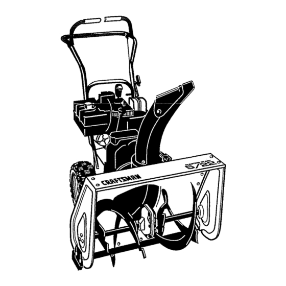
- Page 9 KNOW YOUR SNOW THROWER READ THIS OWNER'S MANUAL AND SAFETY RULES BEFORE OPERATING SNOW THROWER. Compare the illustrations with your SNOW THROWER yourself with the location of various controls and adjustments. Save this manual for future reference. Choke On Engine Engine Start Drive Clutch...
-
Page 10: To Throw Snow
Always wear safety glasses or eye shields while operating the snow thrower. We recommend standard safety glasses or a wide vision safety mask for over your glasses, available at Craftsman Stores or Service Centers° CAUTION: Read owner's manual before operating machine. Never direct discharge toward bystanders. - Page 11 ° For ease of maneuverability in light snow conditions, disconnect the klick pin from the wheel locked position and push into the single wheel drive (klick pin through axle hole only) position (see figure below). o Make sure that the klick pin is in the single wheel drive position of the axle only and not through the locked position.
-
Page 12: Cold Start
Make sure to wipe up any spilled fuel be- fore starting the engine. Store gasoline in a clean, approved con- tainer and keep the cap in place on the container. TO STOP ENGINE o To stop engine, move the throttle control lever to Q (STOP) position and remove key. -
Page 13: Warm Start
COLD START o Be sure the auger drive and traction drive levers are in the disengaged position. • Move the throttle control to _ position. See figure on page 9 for Ioca o tion. ° Remove the keys from the plastic bag° In- sert one key into the ignition sloL Be sure it snaps into place. - Page 14 snow blowing is accomplished snow is removed immediately falls. o For complete snow removal, slightly over- lap each path previously taken. Use more overlap in deep snow to prevent overloading. o The snow should be discharged wind whenever possible, in windy condi- tions, lower the chute deflector to direct discharged snow close to the ground,...
-
Page 15: General Recommendations
GENERAL RECOMMENDATIONS The warranty on this snow thrower does not cover items that have been subjected to op- erator abuse or negligence. To receive full value from the warranty, the operator must maintain the snow thrower as instructed in this manual. The maintenance chart is pro- vided to assist the operator in properly maintaining the snow thrower. -
Page 16: Oil Recommendation
LUBRICATION - Hex Shaft and Gears - Hex shaft and gears require no lubrication. All bearings and bushings are lifetime lubricated and require no maintenance. NOTE: Arty' greasing or oiling of the above components can cause contamination the friction wheel. If the disc drive plate or friction wheel comes in contact with grease or oil, damage to the friction wheel will re- sult. -
Page 17: To Adjust Skid Height
CAUTION: Always disconnect the spark plug wire and tie back away from the plug before making any adjustments or repairs. TO ADJUST SKID HEIGHT This snow thrower is equipped with two height adjustment skids, located on the out- side of the auger housing (see figure be- low). -
Page 18: To Replace Belts
TO REPLACE BELTS The drive belts on this snow thrower are of special construction and should be replaced with original equipment your nearest Craftsman Center. You will need the assistance person while replacing the belts, Drain the gasoline from the fuel tank by re- moving the fuel line at the carburetor. -
Page 19: Traction Drive Belt
* Loosen the belt guide (see third figure on page !8) and pull away from the engine drive pulley+ , Loosen nut on the auger idler pulley (see third figure on'page 18) _nd pull idler pul- ley away from the bell o Remove top two bolts that secure auger housing to motor mount frame. -
Page 20: To Replace Friction Wheel
= Position the shifter lever in first (1) forward gear. o Note the position of the friction wheel on the disc drive plate. The right outer side of the disc drive plate should be 3" from the center of the friction wheel (See figure be- low) Wheel ----Hex... -
Page 21: To Adjust Carburetor
If you think the engine-governed high speed needs adjusting, contact your nearest Craftsman Service Center, which has the proper equipment and experience to make any necessary adjustments. TO ADJUST OR REPLACE... -
Page 22: Snow Thrower
NOTE" A yearly checkup or tune-up by a Craftsman Service Center is a good way to insure that your snow thrower will provide maximum performance for the next season. - Page 23 Stop engine immediately disconnect spark plug wire. Tighten all bolts and make all necessary repairs. If vibration continues, have the unit ser- viced by a Craftsman repairman Replace drive belt Adjust traction drive cable Repair friction wheel Replace auger belt...
- Page 24 Washer, Flat .765xl .12x.06 586251 Spacer, Slev 586253 Pulley, Engine V4L 581264 Belt, V 4L 35.6 LG 50677 Washer, Flat 71063 Washer, Hvsptlk °38 71015 Screw, 3/8-24x1°00 All unnumbered items are interchangeable with opposite side 536.886141 319051B 3269281 PART NAME...
- Page 25 Bolt, .625x. 135 53704 Spring, Idler Tract Drive 76'1760 Screw, 3/8-16xl .25 50793 Pulley, Idler 1.88x.75 Nut, 3/8-16 Ctrfkjam 760478 Cover, Belt w/Storage 310169 Screw, I/4-20x.63 71067 Washer, Flat _281x.63x.065 760539 Lid, Belt Cover 760988 Spring, Idler Auger Drive 536.886141 344688A...
- Page 26 CRAFTSMAN REF. PART NO. PART NAME 190' "76_'"_20 Lever, Assy.Tract, Clutch 53703 Brng, Ft .503 td x.750 20864 Ring, Ret E _39x.04 53818 Spring, Return 579937 Lever, Spring Trac CL 11871 Screw, 1/4-20x.63 73826 Nut, 1/4-20 Reghexctdk 583163_653 Disc, Assy Fdc. Wheel...
-
Page 27: Gear Case Assembly
431787 50221 583125 580295 454565 48275 50684 50304 9566 760194-853 454565 536.886141 313996B PART NAME Key, Wdrf #61 Brng, R .502 IDx352x.75 Shaft, Worm Imp Collar, Thrust Ptn, Spdng o250DIAx1.25 Washer,Flat352x1_24x.093 Brag, Roll Brag, Ft 3521Dxl _002OD Seal, Oil .75x1.19x25 Impel Assy. - Page 28 22" - 5H.P, SNOW THROWER AUGER HOUSING ASSEMBLY REF. PART NO. 9517 711862 9357 301380-853 34072O 71O71 71060 71037 536.886141 339972G PART NAME Brng,Ft .754 Nut, Toplock 5/16-18 Screw, 5/16-18x.75 Skid, Height Adjust Bolt 5/16-18x_75 Cam Washer, Flat.349x.69x.066 Washer, Sptlk .,31x.58xo08 Nut, 5/16-t8...
- Page 29 305216 586280 71071 71038 760268 760987 585214-853 302628 71067 780029 337227 585193 536.886141 337160E PART NAME Upper Chute Pin, Hinge Bolt 5/16-18xl .00 Cam Washer, Flat.349xo69x.066 Nut, 5/16-18 Hexnyl Flap, Chute Insert Rivet, Pop .125x.232 Collar, Chute Rect. Screw, 1/4-20xo75 Washer, Flat.281x.63x,065...
- Page 30 PART NO. 579869 1673 i745 780029 308146 339541-853 313053 71060 71037 309436 337407-853 6751 300303 536.886141 339622C PART NAME Spring, Tension Spring, Auger Clutch Nut, 1/4o20 Hex Nylock Boot, Clutch Spring Handle, Lower Screw 5/16-18xl .00 Washer, Sptlk _31x.58x.08 Nut, 5/16-18 Reghex...
- Page 31 73826 Nut, 1/4-20 Reghexctrlk 579944 Brng, F! .500[Dx.88ODx°31 581795 Rod, Assy Yoke 71111 Nut, 3/8-16 Hexctrlk 536.886141 318542F PART NAME Bushing, Wheel 4"Lg Tire & Rim 12x4.1x6 Screw Shr 1/4-20xt .75 Nut, 1/4-20 Hex Nylock Ring, ReL Pin, Kltk .25xl .38...
- Page 32 308145 Boot, Eye Bolt Chute Crank 71045 Nut, 3/8-16 Hexjam 71072 Washer, Flat .406x.81x.066 VIEW FROM AUGER FRAME REAR 22" - 5H.P. SNOW THROWER 536.886141 REF. PART 309344 - Adaptel:, BoOt to 71072 Washer, Rat o406x,8 lx..066 71046 Nut, 3/8-16 Hexnyl...
- Page 33 CRAFTSMAN 4.-CYCLE ENGINE MODEL NUMBER 143.995001 CARBURETOR 640084A PART# PART NAME i ,,,, 631615 THROTTLE SHAFT & LEVER AssY, 631767 THROTTLE RETURN SPRING 640070 THROTTLE SHUTTER THROTTLE 650506 SHUTTER SCREW 632108 CHOKE SHAFT & LEVER ASSY 631890 CHOKE SHUTTER 630735...
- Page 34 CRAFTSMAN 4-CYCLE ENGINE MODEL NUMBER 143.995001 >...
- Page 35 AN 4-CYCLE_ENGINE DR,A SM REF. PART# PART NAME 36469A CYLINDER (INCL, 2,20,72&125) 26727 DOWEL PIN OIL DRAIN EXTENSION RCHASE LOCALLY) 30969 NSION CAP WASHER 28277 31334 GOVERNOR 31510 GOVERNOR LEVER 31335 GOVERNOR LEVER CLAMP 651018 SCREW, TORX T-15, 8-32X19/64' 31426 EXTENSION SPRING 32600...
- Page 36 CRAFTSMAN _CYCLE STARTER NO. 590742 REF. PART# 590742 590740 590616 590617 590645A 590647 590535 590574 590741 ENGINE MODEL NUMBER 143.995001 PART NAME i i i i i,,,i STARTER, REWIND RETAINER DOG, STARTER SPRING, DOG PULLEY & REWIND SPRING ASSY HOUSING ASSY, STARTER ROPE, STARTER (LENGTH 98"...
- Page 37 CRAFTSMAN 4-CYCLE ENGINE MODEL NUMBER 143.995001 STARTER NO. 33290E PART# 33290E 31749 33522 33769 33524 35911 35461 35450 35912 35452A 5905o0 33441 35453 35454 35462 35456 650819 32450B 650759 730623 PART NAME ELECTRIC STARTER (110 VOLT) RETAINER RING SPRING RETAINER...
- Page 38 CRAFTSMAN matedales y mano de obra. Siesta Removedora de nieve Craftsman se usa para prop6sitos comerciales arrendamiento, esta garantia es vdlida durante 90 dfas a partir de la fecha de compra. Esta garantfa no cubre Io siguiente: • Elementos fungibles los cuales se gastan durante el uso normal, tales como bujfas, correas de transmisi6n y clavijas de seguro por esfuerzo codante.
- Page 39 2oNunca permita a nifios operar la removedora de nieve y mant_ngalos fuera del alcance de la misma mientras se encuentra en operaci6n. Nunca permita que adultos operen la removedora de nieve sin instrucciSn apropiadao No fleve pasajeros. 3. Mantenga el &rea iibre de personas, especialmente niSos pequeSos y mascotas.
-
Page 40: Mantenimiento
proputsor o gui'a de descarga, y cuando efectL_e cualesquiera reparaciones, ajustes, o inspecciones. 8. AI limpiar, reparar, o inspeccionar m_quina aseg_rese de que el barreno! propulsor y toda parte mSvil se hayan detenido. Desconecte el alambre de la bujfa y mant_ngato alejado de la bujfa para evitar un arranque accidental. - Page 41 Contenido de la boisa con las partes, indique 1. Manuel del Proptetario(no muestra) Paquete estabilizador de combustible Garantia carta (no muestra) 2 - Una bolsa(no muestra) *2-Tonsurar clavija 4- Arandela plana 11/32 Pulgada 3- Tuerca, 5/16-18 Nylon 3- Pernos de coche, 5/16-18 x 1 Pulgada Partes empaquetadas en forma separada en la caja de cart6n(no se muestran del tamaSo real)
- Page 42 PRECAUClON: Siempre use gafas protectoras o protectores para los ojos cuando monte la removedora de nieve. HERRAMIENTAS REQUERIDAS PARA EL MONTAJE 1 - Nanaja(para cortar cart6n y ataduras pl&sticas) 2 - Llaves de tuercas de 1/2 pulgada(o Ilaves de tuercas ajustables) 2 - l_taves de tuercas de 9/16 pulgada(o Ilaves de tuercas ajustables) 2 - Llaves de tuercad de 3/4 pulgada(o...
- Page 43 NOTA: Si los cables se han desconectado de las palancas de los embragues, los cables como se muestra en figura abajo. NOTA" coloque el trav6s de las ranuras en la placa de cambios_...__._. Aditamento "Z" NOTA: $i los cables se han desconectado de las palancas de los embragues, los cables como se muestra en figura abajo.
-
Page 44: Palanca De Cambios
PARA INSTALAR LA PERILLA DE LA PALANCA DE CAMBIOS Enrosque la perilla en el extreme roscado de la palanca de cambios, hasta que haga contacto con la tuerca hexago- nal y la lengeeta apunte ejos el motor. Apriete la tuerca hexagonal 1/2-13 contra el fondo dela perilla (vea figura abajo). - Page 45 v" LISTA DE REViSiON Antes de operar y disfrutar de su removedora de nieve nuevo, deseamos garantizarle que reciba el mejor rendimiento y la mayor satisfaccion de este producto de calidad. Todos las instrucciones para el montaje han sido completadas. €"...
- Page 46 Llave de ignicion para arrancar el motor inserte Ilave para parar el motor retire ta Ilave Boron electdco Le ignicion Control de estrangulacion '_'_'_L "_celeracion _=_retroceso Patanca de propulsion de oruga Palanca de propulsion del barreno Patanca cambio velocidades Caja de Manija de! arrancador Ajustar de...
- Page 47 Craftsman Center de Servicio. PRECAUClON: Lea el manual del propietario antes de operar la maquina. Jamas dirija la descarga hascia espectadores.
-
Page 48: Antes De Arrancar
COMO USAR EL PASADOR DE EN GANCHE DE LA RUEDA o La rueda izquierda est_ asegurada mediante un pasador de enganche anillo. Vea figura abajm Esta unidad fue despachada con el pasador en la posici6n de enganche (a travds del orificio de la rueda). - Page 49 que est6n equipados con este sistema). Todas las caracterfsticas ajustables por el usuario ya cumpten con las normas, por la tanto no es necesario ningSn otro requisito. ADVERTENClA: La experiencia los combustibles mezclados con alcohol (llamado gasohol o usando etanol o metanol) pueden atraer humedad la cual conduce a ia separaci6n y formaci6n...
- Page 50 o Empuje el bot6n del arrancadorhacia abajo hasta que el motor arranque. No intentar el arranque por mas de 10 sergundos a la vez. Este arrancador el6ctrico est,. protegidoterrnalmente.Si se sobre calienta se detendr& autom_.ticamente y puede ser arrancado nuevamentes61ocuando se ha enfriado hasta una temperaturasegura (se requiere una espera de 5 a 10 minutos aproximadamente).
- Page 51 NOTA: deje que el motor se caliente por algunos minutos antes de soplar nieve, en temperaturas infedores a. 18°C (0°F). • Opere el motor a toda velocidad ,_ (RAPIDO) al remover nieve. ARRANQUE EN CALIENTE Si est& arrancando un motor catiente despu_s de un apag6n corto, deje el estrangulador en "APAGADO"...
-
Page 52: Del Cliente
Nunca ponga el motor PRECAUCION: en marcha en ambientes interiores o en ar- eas encerradas, mal ventiladas. El escape del motor contiene monoxido de carbono, un gas inodoro y letal. Mantenga las manos, pies, cabetlo y vestimenta floja alejados de cualesquiera piezas moviles en el motor yen la removedora... - Page 53 :I'ABLA DE LUBRICACION Lubflque a travSs de la toma de engrase del disco de tracci6n, usando grasa Moly para alia temperatura presi6n (Hi-Temp Moly EP. REMOVEDORA DE NIEVE LUBRICAClON - CADA 25 HORAS = Grasa disco de tracci6n cada 25 horas, al final de la temporada frfa y/o antes de guardar la unidad.
- Page 54 Si cae aceite o grasa sobre el disco de tracci6n o ia rueda de fricci6n, aseg_rese de limpiarlos cuidadosamente, NOTA: Cuando vaya a guardar la unidad, pase una tolla impregnada en aceite de mo- tor 5W30 por el eje hexagonal y los engranajes para evitar su oxidaci6n.
- Page 55 PRECAUCION: Siempre desconecte et atambre de la bujfa y amarrelo alejado de la bujia antes de efectuar cualesquiera ajustes y reparaciones. PARA AJUSTAR LA ALTURA DE LA CORREDERA DE APOYO Esta removedora de nieve est&s equipada con dos correderas de apoyo de altura ajustable, ubicadas en eHado exterior del alojamiento del barreno, vea figura abajo.
- Page 56 Las correas de propulsi6n removedora de nieve son de construcci6n especial y deben ser reemplazadas correas de equipo original disponibtes en su Tienda Craftsman Craftsman mds cercano. Necesitar& la asistencia de una segunda persona mientras reemplaza las correas. Drene la gasolina del tanque de combus- tible removiendo la linea de combustible.
- Page 57 Correa de propulsion Correa de de ta _)ruga propulsion del _ barreno Polea ... Polea de tensora .._!'_F_ _._rop uIsion de la onJga "_{{ (_///_\.del Barreno Polea ",Guia de correa tensora -_('_ enganchado_ __flojar Po,o /,tt IF/ }I tensora/_'J ;/ (_/._] //Polea l/ii'_t _//tensora •...
- Page 58 PARA AJUSTAR LA RUEDA DE FRICCION o Desconecte el alambre de la bujia. o Drene ia gasolina del tanque para com- bustible. Coloque la removedora de nieve en posici6n vertical sobre el extremo del barreno. o Remueva el panel inferior (vea figura abajo).
- Page 59 Craftsman mas cercano, el cuat tiene el equipo y la experiencia apropiado para efectuar los ajustes necesados. ;at Pin...
- Page 60 PARA AJUSTAR O REEMPLAZAR LA BUJIA AVISO: Este sistema de encendido pot chispa cumple con todos los requisitos de las normas canadienses para equipo causante de interferencia. AVISO: Este motor cumple con todas las restricciones actuates referentes a la interferencia electromagn_tica de Australia y Nueva Zelandiao Si tiene dificuitades...
- Page 61 NOTA: Una revisi6n o afinado anual por un Centro de Servicio Craftsman es una buena manera de asegurar que su removedora de nieve le brindar& el mdximo rendimiento la siguiente temporada.
- Page 62 PROBLEMA CAUSA Bujfa defectuosa Dificultad de [Agua o suciedad en el sistema de arranque combustible El motor funciona Lfnea de combustible errdtlcamente )oco combustible Unidad funcionando en el modo ,:EImotor se apaga ESTRANGULACION(CHOKE) El motor funclona Agua o suciedad combustible errdticamente;...
- Page 63 For the repair or replacement parts you need delivered directly to your home Call 7 am-'/' pro, 7 days a week 1-800=366=PART (1-800-366-7278) Para ordenar piezas con entrega a domicilio -1-800-659-7084 For in-house major brand repair service Call 24 hours a day, 7 days a week 1=800=4-REPAIR (1-800-473-7247) Para pedir servicio de reparaci6n a...