Table of Contents
Advertisement
Available languages
Available languages
I CRIIFT$1VIRN°I
Operator's
Manual
Snow Thrower
5.0 Horsepower
Electric
Start
22-inch Single Stage
Auger Propelled
Model 536.881500
CAUTION: Before using this product,
read this manual and follow all of its
Safety Rules and Operating Instructions.
Manual del usario
Quitanieves
de 22 pulgadas
5.0 caballos
de fuerza
(hp)
Monoetapico
Arranque
electrico
Propulsado
por barrena
Modelo 536.881500
PRECAUCION:
Antes de usar este producto,
lea este manual y siga todas las reglas de
seguridad e instrucciones de operaci6n,
Sears, Roebuck
and Co., Hoffman
Estates,
IL 60179 U.S.A.
F-041032C
www.sears.com/craftsman
Advertisement
Table of Contents

Related Manuals for Craftsman 536.881500


Summary of Contents for Craftsman 536.881500
- Page 1 (hp) Monoetapico Arranque electrico Propulsado por barrena Modelo 536.881500 PRECAUCION: Antes de usar este producto, lea este manual y siga todas las reglas de seguridad e instrucciones de operaci6n, Sears, Roebuck and Co., Hoffman Estates, IL 60179 U.S.A. www.sears.com/craftsman F-041032C...
- Page 2 TWO-YEAR WARRANTY ON CRAFTSMAN SNOW THROWER For two years from the date of purchase, when this Craftsman Snow thrower is maintained, lubricated, and tuned up according to the operating and maintenance instructions in the owner's manual, Sears will repair, free of charge, any defect in material or workmanship.
- Page 3 TRAINING OPERATION Read this operating and service instruction Do not operate this snow thrower if you are manual carefully. Be thoroughly familiar taking drugs or other medication which can with the controls and the proper use of the cause drowsiness or affect your ability to snow thrower.
- Page 4 14. Do not overload the snow t hrower capacity Store the snowthrower away from ignition byattempting toclear snow attoo fast a sources or appliances that have a pilot rate. light, such as hot water and space heaters, 15. Never operate thesnow thrower athigh clothes dryers, etc..
- Page 5 Drive Clutch Forward Reverse Auger Clutch Auger Collector Engage Push To Engage Fuel Electric Starter Discharge DOWN Discharge UP Discharge LEFT Discharge RIGHT Weight Transfer Weight Transfer Transmission Ignition Key Lift Handle To Depress Pedal Insert To Run, Engage To Disengage Pull Out To Stop.
- Page 6 Contents of Parts 1 - Owner's Manual (not shown) 1- Container 20 ounce Craftsman 5W30 oi! 1 - Electric Starter Cord (not shown) 1 - Fue! Stabilizer (not shown) REMOVE FROM safety glasses or eye shields ARNING: Always wear CARTON...
- Page 7 How To Assemble The Handle Install the bolt and tighten the T-knob. Remove the T-knobs and U-bolts (Figure 1). Put the upper handle in the opera- Upper Handle tor's position. Install the U-bolts and tighten the Cable T-knobs. Note: Make sure that the cable is not pinched between the upper igure 2 and lower handle.
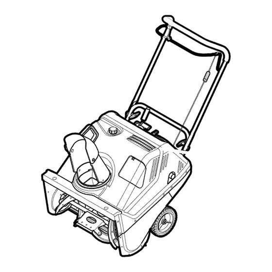
- Page 8 [o_o)_l KNOW YOUR SNOW THROWER READ THIS OWNER'S MANUAL AND SAFETY RULES BEFORE OPERATING YOUR SNOW THROWER. Compare the illustrations with your SNOW THROWER to familiarize yourself with the location of various controls and adjustments. Save this manual for future reference.
- Page 9 [o_o)_l Manual before operating any snow thrower can result WARNING: The operation of WARNING: Read Owner's machine. Never direct dis- in foreign objects being thrown into the eyes, which can re- charge toward bystanders. Stop the sult in severe eye damage. Always engine before unclogging discharge wear safety glasses or eye shields...
- Page 10 NOTE: To avoid engine problems, unit or purchase Craftsman Fuel fuel system must be emptied before Stabilizer No. 3550. Make sure that storage for 30 days or longer.
- Page 11 [o_o)_l • Never fill the tank completely. Fill mable. Always use caution the tank to approximately 1-1/2" WARNING: Gasoline is flam- when handling or storing below the top of the tank opening gasoline. to provide space for expansion of fuel. •...
- Page 12 [o_o)_l If your system is grounded and a equipped with a three-wire three-hole receptacle is not avail- WARNING: The starter i8 power cord and plug and is able at the point your starter will designed to operate on 120 volt AC normally be used, one should be household current.
- Page 13 [o_o)_l 6. (Recoil Start) Turn the key to the disconnect the power cord from the starter motor. ON position (see Figure 11). Slowly pull the recoil starter handle until Pull starter handle rapidly. resistance is felt and then pull repid- ly to start the engine (see Figure 12).
- Page 14 [o_o)_l HOW TO REMOVE OBJECTS • Release auger drive lever. FROM AUGER • Rotate the ignition switch key to the stop position to stop the engine. • Disconnect spark plug wire. to remove any item that may ARNING" Do not attempt become lodged in auger •...
- Page 15 CUSTOMER RESPONSIBILITIES SERVICERECORDS Fill in dates as you Before Every Every Every Every completeregular Each Each Before service. Often Hours Hours Hours Hours Season Storage Change Engine Oil Tighten All Sprewsand Nuts Check and Clean Spark Plug Clean and Inspect Spark Arrestor Check Fuel Check...
- Page 16 ENGINE SPECIFICATIONS Engine Power & Torque Rating Proce- dure) (Revision 2002-05). Given both HORSEPOWER 5 HP the wide array of products on which engines are placed, and the variety DISPLACEMENT 148 cc environmental issues applicable operating the equipment, it may be that BORE 65mm (2.562 in.) the engine...
- Page 17 Change the oil every fifty (50) hours or "To Add Oil" in the Operation Sec- tion. at least once a year if the snow thrower is not used for fifty (50) hours. TO CHANGE ENGINE OIL 1. Position the snow thrower so that the oil drain plug is at the lowest point on the engine.
- Page 18 dental starting when making WARNING: To prevent acci- any adjustments or repairs, always disconnect the spark plug wire and place it where it cannot make contact with the spark plug. ADJUST AUGER CONTROL CABLE Install the "Z" hook to the auger The auger control cable is adjusted at the...
- Page 19 HOW TO REMOVE THE TOP COVER 8. To install the top cover, reverse the above steps. 1. Remove the discharge chute. See "How To Remove The Discharge HOW TO REMOVE THE BELT COVER Chute". 1. Remove the bolts (E) and nuts that 2.
- Page 20 TO REPLACE DRIVE BELT The drive belt is of special construction and must be replaced with original fac- tory replacement belt available from your nearest Sears service center. Remove the belt cover. See "How To Remove The Belt Cover". Belt Guide Remove the drive belt from the...
- Page 21 Chute HOW TO REMOVE THE CHUTE 1. Remove the fasteners that secure the chute to the top cover. 2. Remove the chute. Cover Figure 24 HOW TO ADJUST THE BRAKE PAD 3. Tie the auger drive lever to the han- IMPORTANT: An adjustment is only...
- Page 22 If gasoline remains in the tank, or purchase Craftsman Fuel Stabi- fumes may reach an open flame, lizer No. 3550. Add fuel stabilizer spark or pilot light from a furnace,...
- Page 23 _ol_]_ln_]:[oIo_il_[_ TROUBLE CORRECTION CAUSE Difficult starting Replace spark plug. Defective spark plug. Drain and clean the fuel tank. Water or dirt in fuel system. Refill with fresh fuel mixture. Engine runs erratically Blocked fuel line, empty gas Clean fuel line; check fuel tank, or stale fuel mixture.
- Page 24 (This page applicable in the U.S.A. and Canada only.) Sears, Roebuck and Co., U.S.A. (Sears), the California Air Resources Board (CARB) and the United States Environmental Protection Agency (U.S. EPA) Emission Control System Warranty Statement (Owner's Defect Warranty Rights and Obligations) EMISSION CONTROL WARRANTY...
- Page 25 Sears Emission Control Defects Warranty Provisions The following are specific provisions relative to your Emission Control Defects Warranty Coverage. It is in addition to the Sears engine warranty for non-regulated engines found in the Operating and Maintenance Instructions. Warranted Parts defective, if the diagnostic work is per-...
- Page 26 Look For Relevant Emissions Durability Period and Air Index Information On Your Engine Emissions Label Engines that are certified to meet the California Air Resources Board (CARB) Tier 2 Emission Standards must display information regarding the Emissions Durability riod and the Air Index. Sears, Roebuck and Co., U.S.A.
- Page 27 F041032C...
- Page 28 CRAFTSMAN 22" 5HP SNOW THROWER 536.881500 ENGINE DRIVE ASSEMBLY F 041032C...
- Page 29 CRAFTSMAN 22" 5HP SNOW THROWER 536.881500 ENGINE DRIVE ASSEMBLY PART DESCRIPTION PART DESCRIPTION Engine 320077 Arm, Idler 1501849E701 Cradle Assy, Engine 313436 Rod, Clutch Linkage 1501872 Frame, Left 48924 Pulley, Idler 1502027 Mount, Antivibration 302637 Screw, 3/8 16Xl .50 lx216...
- Page 30 CRAFTSMAN 22" 5HP SNOW THROWER 536.881500 FRAME AND FUEL TANK F 041032C...
- Page 31 CRAFTSMAN 22" 5HP SNOW THROWER 536.881500 FRAME AND FUEL TANK PART DESCRIPTION 302628 Screw 1/4 20 x .75 71067 Washer 1501876E701 Bracket, Fuel Tank 1501726 Cap, Fuel Tank 1501875 Tank, Fuel 73826 Nut, Hex 1/4 20 71391 Nut, Hex 5/16 1502028 Tubing, Fuel Line 12"...
- Page 32 CRAFTSMAN 22" 5HP SNOW THROWER 536.881500 AUGER HOUSING Ref, Frame and Fuel Tank Ref. Frame and Fuel Tank page PART PART DESCRIPTION DESCRIPTION 710263 Screw 1/4 20 x 1 .O0 580251 Retainer, Bearing 73826 Nut, Hex 1/4 20 43846 Bearing 302628 Screw, 1/4 20 x .75...
- Page 33 CRAFTSMAN 22" 5HP SNOW THROWER 536.881500 ELECTRIC STARTER Ref. Body page PART PART DESCRIPTION DESCRIPTION 311633 Screw, No. 8 32 x 3.00 Bolt, Muffler 414106 Washer 71060 Washer, Split Lock 271163 Nut, Keps No. 8 71037 Nut, Hex 5/16 Lever, Choke...
- Page 34 CRAFTSMAN 22" 5HP SNOW THROWER 536.881500 HANDLE ASSEMBLY 3- i Ref. Frame and Fuel Tank page F 041032C...
- Page 35 CRAFTSMAN 22" 5HP SNOW THROWER 536.881500 HANDLE ASSEMBLY PART NO, DESCRIPTION 1502001 Handle & Grip Assembly 1501861 E701 Control, Bail 308146 Boot, Clutch Spring 1502042 Cable, Upper Control 313441 Bracket, Control Adjust 313448 Cable, Lower Control 313471 Spring 1501877 U Bolt...
- Page 36 CRAFTSMAN 22" 5HP SNOW THROWER 536.881500 CHUTE ASSEMBLY 22 --q 1928 Ref, Auger page F 041032C...
- Page 37 CRAFTSMAN 22" 5HP SNOW THROWER 536.881500 CHUTE ASSEMBLY PART DESCRIPTION PART DESCRIPTION 313685 Screw 1/4 14 1501067 Gear, 9 Tooth 1501853 Retainer, Chute Ring 313685 Screw, 1/4 14 x .75 1501864 Ring, Chute 331532 Nut, Push 340720 Bolt, Cart 5/1_18x.75...
- Page 38 CRAFTSMAN 22" 5HP SNOW THROWER 536.881500 TOP COVER 24 6 Ref, Auger Housing page F 041032C...
- Page 39 CRAFTSMAN 22" 5HP SNOW THROWER 536.881500 TOP COVER PART DESCRIPTION 1501862 Panel, Control 313674 Screw 1/4 20 x 1.25 71067 Washer 73826 Nut, 1/4 20 1501874 Bushing, Chute Crank 300193 Nut, 5/8-32 49643 Keys & Ring, Starter Bulb, Fuel Primer...
- Page 40 CRAFTSMAN 22" 5HP SNOW THROWER 536.881500 WHEELS PART DESCRIPTION 577598 Retainer, E Ring 71072 Washer 760713 Wheel and Tire 7" x 1.50" 309656 Sleeve, Spacer 1501879 Rod, Axle 583409 Washer F 041032C...
- Page 41 DESCRIPTION 48x5635 Decal, Panel 22" ES SEARS 48x5638 Decal, Electric Start 70141 Decal, Auger Danger 48x5642 Decal, Danger Chute Hand 48x5551 Decal, 5HP/22" CRAFTSMAN 69880 Decal, Danger Muffler 761150 Decal, Auger Control 48x5658 Decal, Spark Plug Access 22" F 041032C...
- Page 42 BRIGGS & STRATTONENGINEMODEL 9A413-O202-E1 ENGNE _KET _E'I' 45 ( ..15 _ _4 _9¸ 10_ OPERAI_O_'_ _NUAt Assemblies include all parts shown in frames. F 0410320...
- Page 43 BRIGGS & STRATTONENGINEMODEL 9A413-O202-E1 PART PART DESCRIPTION DESCRIPTION 699088 Cylinder Assembly 691719 Dipper-Connecting 399269 Kit-Bushing/Seal (Magneto Side) 691664 Screw _299819 Seal-Oil (Connecting Rod) (Magneto Side) 497871 Valve-Exhaust 690386 Head-Cylinder 296677 Valve-intake 7_Q698717 Head-Cylinder Gasket 690520 Spring-Valve 699448 Breather Assembly (Intake) 695890 Gasket-Breather 690520...
- Page 44 BRIGGS& STRATTONENGINEMODEL 9A413-O202"E1 63&& • < >76 ft76 _* CAI_L_ )[¢_q L>_ Oxfid:_FIA _J'L K_'f _0_, Assemblies include all parts shown in frames. F 0410320...
- Page 45 BRIGGS & STRATTONENGINEMODEL 9A413-O202-E1 PART PART DESCRIPTION DESCRIPTION _692218 Gasket-Crankcase 691412 Lever-Governor 699096 Cover-Crankcase Control 692020 Seal-Oil 691846 Spring-Governor Link (PTO Side) e_,271716 Washer-Sealing 281658 Cap-Oil Fill (Float Bowl) 691129 Screw 699565 Muffler (Crankcase Cover) 496914 Armature-Magneto Note-- 691061 Screw 691128 Screw (Magneto...
- Page 46 BRIGGS & STRATTONENGINEMODEL 9A413-O202-E1 < Assemblies include all parts shown in frames. F 041032C...
- Page 47 BRIGGS & STRATTONENGINEMODEL 9A413-O202-E1 PART PART DESCRIPTION DESCRIPTION 699573 Flywheel 281505 PawI-Rachet 692144 Housing-Rewind 699091 Dipstick Starter 691876 Seal-Dipstick Tube 697316 Rope-Starter 699090 Tube-Dipstick (Cut to 690600 Required Length) (Rewind Starter) 691915 Grip-Starter Rope 691696 Screw 690637 Screw (Pawl Friction Plate) (Rewind Starter)
- Page 48 F 041032C...
- Page 49 F041032C...
- Page 50 ... SiMBOLOS INTERNACIONALES ENSAMBLAJE ....PEDIDO DE PIEZAS/SERVICIO GARANTJA LIMITADA DE DOS AI_IOS PARA EL QUITANIEVES CRAFTSMAN Durante dos aries a partir de la fecha de compra, siempre que a este quitanieves Craftsman se le de mantenimiento, lubricaci6n y afinamiento...
- Page 51 CAPACITACION y/o del sol hace que el combustible se expanda. Lea con atenci6n las instrucciones en e! manual de operaci6n y servicio. Familiari- Para todos los quitanieves con motores de arranque electrico, use cables de ex- cese completamente con los controles y tensi6n con certificaci6n OSA/UL.
- Page 52 necte e lcable d elabujia y mant6ngalo siempre que tiene buena estabilidad, alejado delabujia para e vitar unarran- sujete con firmeza elmango. Oamine; nunca c orra. que accidental. 9. Tome todas lasprecauciones posibles 20.No trate dealcanzar areas dificiles. Man- dejar elquitanieves desatendido.
- Page 53 IMPORTANTE: Muchos de estos simbolos estAn colocados en su quitanieves o estAn impresos en los manuales que vienen con el producto. Antes de operar el quitanieves aprenda y comprenda el objetivo de cada s[mbolo. Simbolos de control y operacibn Despacio Rapido Arranque electrico Arranque de motor...
- Page 54 Simbolos de control y operacion Combustible Aceite Descarga hacia Descarga haeia Descarga hacia la Descarga hacia la ABAJO ARRIBA IZQUIERDA DERECHA Transferencia de peso Transferencia de peso Llave de encendido Levante el mango Presione el pedal Insertar para marcha, para enganehar, para desenganehar.
- Page 55 Localice y retire la botella de aceite de blaje del quitanieves. motor 5W30 Craftsman de 2 tiempos. Localice todas las partes envueltas por separado y s&quelas de la caja, Retire y descarte todo el material de em-...
- Page 56 Como ensamblar el mango Mango Quite las perillas en "T" y los pernos en superior "U" (Figura Ooloque el mango superior en la posi- Cable ci6n de operaci6n. Instale los pernos en "U" y apriete las Perilla en "T" perillas en "T'.
- Page 57 CONOZCA SUQUITANIEVES LEA ESTE MANUAL DEINSTRUCCIONES YLAS REGLAS DE SEGURIDAD TESDEOPERAR SUQUITANIEVES. Compare estas i lustraciones con suQUITANIE- VES para f amiliarizarse con laubicaci6n delos diversos controles yajustes. Guarde este manual para r eferencia futura. Palanca depropulsi6n delabarrena - - Llave de Manivela encendido...
- Page 58 del propietario antes de operar de cualquier quitanieves puede ADVERTENCIA: Lea el manual ADVERTENCIA: La operacion la maquina. Nunca dirija la des- provoear que objetos extrahos carga hacia los transeuntes. Pare el mo- sean lanzados con fuerza haoia sus tor antes de desobstruir el tubo de des- ojos, Io cual podria resultar...
- Page 59 ANTES DE HACER ARRANCAR 5. De set necesario, a_ada aceite hasta la EL MOTOR linea "FULL" (LLENO) en la tapa/varilla indicadora del nivel de aceite (vea la 4. Antes de dar servicio o encender el mo- Figura 7). No Io Ilene demasiado. tor, familaricese con el quitanieves.
- Page 60 Se recomienda Craftsman. Aseg0rese de que el recipien- ahadir unestabilizador decombustible te que contiene la gasolina a utilizar, este lagasolina. Use elestabilizador limpio y sin 6xido u otros residuos. Nunca viene c on launidad ocompre elEstabili-...
- Page 61 Si su sistema esta conectado a tierra arranque esta equipado con un pero no dispone de un tomacorrientes DVERTENCIA: El motor de cable de alimentaci6n y enchu- trifilar, en un punto conveniente para fe trifilar, diseftados para funcionar enchufar su arrancador electrico, pida corriente domestica de 120 voltios CA.
- Page 62 tencia. Entonces, tirer_tpidamente del tomacorrientes y luego del mo- cord6n para e ncender elmotor (vea la tor de arranque. Figura 12). No suelte lamanija d earran- Jale r&pidamente la manija qus manual inmediatamente despu6s de arranque. jalarla. Deje q ue seenrolle lentamente. 7.
- Page 63 COMO RETIRAR OBJETOS • Suelte la palanca de propulsi6n de la ba- ATASCADOS EN LA BARRENA rrena. • Gire la Ilave de ignici6n (encendido) a la posici6n stop para parar el motor. • Desconecte el cable de la bujia. mover ningun objeto atascado ADVERTENCIA: No intente re- •...
- Page 64 L_-' h, h, u h, o] RESPONSABILIDADES DEL PROPIETARIO REGISTROSDE SERVICIO Anotelas fechas en que Antes Cada Cada Cada Cada Cada se hace mantenimiento de ca- A me- esta- Antesde regular da uso nudo horas horas horas horas ci6n guardado Revisar el nivel de aceite det motor Oambiar el aceite del...
- Page 65 L_-' h, h, u h, o] ESPEClFICAClONES DEL MOTOR (Procedimiento de Clasificaci6n de Potencia & Torque del Motor Pequefio) (Revisi6n 2002-05). Dado ambos un amplio conjunto CABALLOS 5 HP de productos en los cuales son puestos FUERZA nuestros motores, y la variedad de emisio- ClUNDRADA 148 cc nes ambientales...
- Page 66 L_-' h, h, u h, o] MASIADO. Oonsulte "Para afiadir Oambie el aceite cada cincuenta (50) horas de uso, o pot Io menos una vez al aSo si el aceite" en la secci6n de Operaci6n. quitanieves no se usa por cincuenta (50) horas.
- Page 67 L_-' h, h, u h, o] el arranque accidental del mo- ADVERTENCIA: Para prevenir tor, siempre desconecte el ca- ble de la bujJa y mantengalo alejado de esta, mientras realiza ajustes o repara- clones a la unidad. C6MO AJUSTAR EL CABLE DE CONTROL DE LA BARRENA El ajuste del cable de control de la barrena...
- Page 68 _"]=l_Ivi[o][o] h,'d P'i_llllI_"_ COMO QUITAR LA CUBIERTA SUPERIOR Para montar la eubierta superior, reali- ce los pasos anteriores en orden inver- Desmonte el tube de descarga. Quite la tapa del tanque de combustible, COMO QUITAR LA CUBIERTA DE LA CORREA Quite los dos pernos (A) y tuercas Quite los pernos (E) y las tuercas que la parte del frente de la eubierta...
- Page 69 _"]=l_Ivi[o][o] h,'d P'i_llllI_"_ C6MO REEMPLAZAR LA CORREA DE TRANSMISI6N 9. Instale la cubierta de la correa. Consulte La correa de transmisi6n est& construida es- "O6mo quitar la cubierta de la correa". pecialmente para la unidad y debe ser reem- plazada dnicamente con una correa original de f&brica para su unidad, disponible en su centro de servicio Sears m&s cercano.
- Page 70 _"]=l_Ivi[o][o] h,'d P'i_llllI_"_ COMO DESMONTAR TUBO Tube de descarga DESCARGA Quite los pernos que sujetan el tu- bo de descarga a la ¢ubierta perior. Quite e! tubo de deecarga. Oubierta superior Figura 24 COMO AJUSTAR LA ZAPATA DE FRENO IMPORTANTE: El ajuste es necesario sola- Ate la palanca del propulsor de la barre-...
- Page 71 Craftsman ma expuesta, chispa o llama piloto N0m. 3550. Afiada el estabilizador de una caldera, calentador de combustible...
- Page 72 PROBLEMA CAUSA CORRECClON Dificultad para Bujia defectuosa. Reemplace la bujia defectuosa. arrancar Agua o suciedad en el sistema Vacie y limpie el tanque de de combustible, combustible; vuelva a Ilenar el tanque con una mezcla fresca de combustible. El motor funciona Lfnea de combustible bloqueada, Limpie la linea de combustible;...
- Page 73 (Estap_gina es aplicableQnicamente en EstadosUnidosde Am6ricay Canada.) Sears, Roebuck and Co., U.S.A. (Sears), Junta de Recursos Ambientales de California (CARB) y Agencia de Proteccion Ambiental de los Estados Unidos (U.S. EPA) Declaracion de la Garantia del Sistema de Control de Emisiones (Derechos Obligaciones del Propietario de la Garantia de Defectos) LA COBERTURA DE LA GARANTIA DEL CONTROL DE EMISIONES ES APLICABLE A LOS...
- Page 74 Provisiones de la GarantJa de Defectos del Sistema de Control de Emisiones Sears Las siguientes son provisiones especificas de diagn6stico la cual conduce a la determi- lativas a la Cobertura de Garantia de Defectos naci6n de que esa Parte Garantizada es de- del Sistema de Control de Emisiones.
- Page 75 Busque el Periodo de Durabilidad de Emisiones y la Informaci6n del indice de Aire Pertinentes en su Etiqueta de Emisiones del Motor Los motores que son certificados para cumplir con las Normas de Emisiones Etapa 2 de la Junta de Recursos Ambientales de California (CARB) deben mostrar la informaci6n referente al Perio- do de Durabilidad de Emisiones y al Indice de Aire.
- Page 76 Your Home For repair -- in your home - d all major brand appliances, iiiiiiiiiiiiiiii_ii_ iiiiiiiiiiiiiiii ¸ lawn and garden equipment, or heating and cooling systems, iiiiiiiiiiiiiiii no matter who made it, no matter who sold it! iiiiiiiiiiiiiiii For the replacement pa_s, accessories and iiiiiiiiiiiiiiii owner's manuals that you need to do-it-yourself, iiiiiiiiiiiiiiii...