Table of Contents
Advertisement
Available languages
Available languages
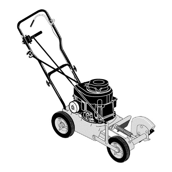
Operator's
Manual
Edger
3.5 Horsepower
9 Inch Blade
Model 536.772320
CAUTION: Before using
this product, read this
manual and follow all of its
Safety Rules and
Operating Instructions.
- CRRFTSMRN °
Manual del usario
Orilladora
3.5 caballos
de fuerza
(hp)
de 9 pulgada
I&mina
Modelo
536.772320
PRECAUCI6N:
Antes de usar este
producto, lea este manual y siga
todas las reglas de seguridad e
instrucciones de operaci6n.
Sears, Roebuck
and Co., Hoffman
Estates,
IL 60179 U.S.A.
F-021104L
www.sears.com/craftsman
Advertisement
Table of Contents

Related Manuals for Craftsman 536.772320


Summary of Contents for Craftsman 536.772320
- Page 1 (hp) de 9 pulgada I&mina Modelo 536.772320 PRECAUCI6N: Antes de usar este producto, lea este manual y siga todas las reglas de seguridad e instrucciones de operaci6n. Sears, Roebuck and Co., Hoffman Estates, IL 60179 U.S.A. www.sears.com/craftsman F-021104L...
-
Page 2: Table Of Contents
Sears will repair, free of charge, any defect in material or workmanship. If this Craftsman Edger is used for commercial or rental purposes, this warranty applies for only 90 days from the date of purchase. -
Page 3: Safety Rules
SAFETY RULES Safe Operation Practices Edger. WARNING: Look for this symbol to point out important safety precautions. It means: "Attention! Become Alert! Your Safety Is Involved." Operating Safety tal starting when setting-up, ARNING: To prevent acciden- Never allow children or young teenagers to transporting, adjusting or mak- operate the Edger. - Page 4 SAFETY RULES spect the Edger for any damage, and re- Safe Storage pair the damage before restarting and • Always refer to the owner's manual instruc- operating it. tions for important details if the Edger is to be stored for an extended period. If Edger should start to vibrate abnormally, stop engine and check immediately for the...
- Page 5 SAFETY RULES INTERNATIONAL SYMBOLS IMPORTANT: Many of the following symbols are located on your unit or on literature sup- plied with the product. Before you operate the unit, learn and understand the purpose for each symbol. Control And Operating Symbols Slow Fast Fuel...
-
Page 6: Assembly
ASSEMBLY ASSEMBLY 1 - Control Rod Parts Packed Separately In Carton 1 - Owner's Manual (not shown) 1 - Container Of Oil 2 - Hair Pin 1 - Control Rod 1 - Hair Pin 1 - Container of Oil from the carton. glasses or eye shields while as, WARNING: Always wear safety... - Page 7 ASSEMBLY HOW TO RAISE THE HANDLE Insert the other end of the control rod, Loosen the knobs and raise the upper handle to the upright position. See from RIGHT to LEFT, through the hole in Figure 2. the depth control lever and fasten with hair pin.
- Page 8 ASSEMBLY HOW TO PREPARE THE ENGINE Fill With Oil How To Add The Engine 1. Put the Edger on a level surface. This Edger was shipped with a container of SAE30 motor oil. Add this oil to the engine 2. Remove the oil fill cap (Figure 6). before operating.
- Page 9 ASSEMBLY _" CHECKLIST For the best performance and satisfaction from this quality product, please review the following checklist before you operate the Edger: All assembly instructions have been completed. Check carton. Make sure no loose parts remain in the carton. All fasteners have been properly tight- ened.
-
Page 10: Operation
OPERATION KNOW YOUR EDGER READ THE OWNER'S MANUAL AND ALL SAFETY RULES BEFORE YOU OPERATE the Edger. To familiarize yourself with the location of the controls, compare the illustrations with your Edger. Save this manual for future reference. Engine Stop Lever Air Filter Depth Control Lever Control Rod... - Page 11 OPERATION THE DEPTH CONTROL LEVER runs, the blade will rotate. To HOW TO USE WARNING: When the engine prevent injury, keep hands and feet away from blade. Start the engine. To lower the cutting blade, pull the depth HOW TO STOP THE EDGER control lever back.
- Page 12 OPERATION HOW TO STOP THE ENGINE To stop the engine, release the engine stop lever. If the engine will not stop, hold a screwdriver against the spark plug and against the en- gine cooling fins. The spark will go to ground and the engine will stop.
- Page 13 OPERATION EDGING TIPS • Edging is best performed when conditions are dry. If the soil is to wet, dirt becomes packed around the blade causing prema- ture belt wear and decreased perfor- mance. • If dirt does become packed around the blade, stop the engine and remove the wire from the spark plug.
-
Page 14: Maintenance
MAINTENANCE CUSTOMER RESPONSIBILITIES SERVICE RECORDS Fill in datesas you Every Every Before Before Before SERVICE completeregular Each Each service, Often Hours Hours Season Storage DATES Lubricate Wheel Axles Change Engine Oil Check Spark Plug Tighten All Fasteners Lubricate Quill Rod/ tube PRODUCT SPECIFICATIONS GENERAL RECOMMENDATIONS... - Page 15 MAINTENANCE LUBRICATION After each 25 hours, apply a small amount of engine oil to all moving parts, particularly the wheels. How To Change The Engine Change the oil in the engine crankcase after each 25 hours of use. NOTE: The oil will drain more freely when the engine is warm.
- Page 16 MAINTENANCE SPARK PLUG Check the spark plug every 25 hours. Re- moval. Tighten the spark plug to a torque place the spark plug if the electrodes are of 15 foot-pounds. pitted, burned, or if the porcelain is cracked. Feeler Gauge Make sure the spark plug is clean.
-
Page 17: Service And Adjustment
SERVICE AND ADJUSTMENT HOW TO REMOVE THE BELT The belt made of a special compound. If the To compress the spring and release ten- belt becomes worn or breaks, replace the sion on the belt, push the blade bearing belt with an original equipment belt. housing back toward the engine (see Figure 16). - Page 18 SERVICE AND ADJUSTMENT HOW TO REPLACE THE BLADE Remove the blade Iocknut that holds The blade is subject to wear and damage, the blade to the drive shaft. such as nicks and dents. This will not gener- ally affect its function. The blade is designed to not require sharp- ten the blade Iocknut, always WARNING:...
- Page 19 SERVICE AND ADJUSTMENT STORAGE parts such as the carburetor, fuel filter, fuel hose, and tank during storage. Also, Edger indoors with fuel in the WARNING: Never store the fuel tank. Never store in an en- using alcohol-blended fuels (called gaso- hol, ethanol or methanol) can attract closed, poorly ventilated area where moisture which leads to separation...
- Page 20 TROUBLE SHOOTING CHART TROUBLE CAUSE CORRECTION Drain fuel tank. Fill with fresh Engine difficult to start Stale fuel fuel. Clogged fuel filter Replace fuel filter Dirt in fuel tank or out of fuel Clean fuel tank. Engine runs erratically Take unit to a Sears Service Carburetor out of adjustment Center.
- Page 21 SEARS, ROEBUCK AND CO. Federal and California Emission Control Systems Limited Warranty Small Off-Road Engines CALIFORNIA & US EPA EMISSION quired maintenance listed in your Owner's Manual, but Sears, Roebuck and Co. will not CONTROL WARRANTY STATEMENT deny warranty solely due to the lack of receipts The U.
- Page 22 ershall pay any charges formaking service Sears, Roebuck and Co. according to Subsec- calls and/or fortransporting theproducts tion 4 below. Any such part repaired or re- and from the place w here the inspection and/ placed under the ECS Warranty shall be orwarranty work i sperformed.
- Page 23 use shall not r educe Sears, Roebuck and Co. EMISSION-RELATED PARTS ECS Warranty obligations. INCLUDE THE FOLLOWING: 9.Unapproved add-on ormodified parts m ay 1. Carburetor Assembly and its Internal Com- not b eused t omodify orrepair aSears, Roe- ponents buck a nd Co. engine. Such u se voids this ECS a) Fuel filter Warranty and shall besufficient grounds for...
- Page 24 CRAFTSMAN 536.772320 REPAIR PARTS 339589C PARTNO. DESCRIPTION PARTNO. DESCRIPTION 3.5 HP 331076-854 Blade Guard 9G902-0145-D1 2x53 Bolt, Carriage (SeeEngine pages) 15x88 Nut, 5/16-18 47792 Screw 22265 Flat washer 52052 Pulley, V3L 740297 Blade, Edger 338490 Key, Hi Pro #505 46023...
- Page 25 CRAFTSMAN 536.772320 REPAIR PARTS 343716B PARTNO. DESCRIPTION PARTNO. DESCRIPTION Screw 740091 Rod, Axle Front 180091 Flat washer 20864 Ring, Ret E. 120393 740126-854 Arm, Front Wheel 15x88 Nut, 5/16-18 740095 Rod, Axle R. 711008 Washer, Nylon 417098 Flat washer 740046 Spacer, Sleeve Tire &...
- Page 26 CRAFTSMAN 536.772320 REPAIR PARTS 343712C F-O21104L...
- Page 27 CRAFTSMAN 536.772320 REPAIR PARTS PART NO. DESCRIPTION 711558 Bolt, 5/16-18x.75 15x79 Nut, 5/16-18 740128-853 Lower Handle 740130-853 Handle, Depth 180081 Screw 25644 Spring, Compression 1498 Nut, 5/16-18 740143-853 Brkt, Adj. Quadrant 672510 Rope Guide 180024 Screw, 1/4-20xl.25 782585 Nut, 1/4-20...
- Page 28 MODEL 9G902-0145-D1 REPAIR PARTS 200_ 718 [_ 524 0 24 [_ F-O21104L...
- Page 29 MODEL 9G902-0145-D1 REPAIR PARTS PART KEY PART DESCRIPTION DESCRIPTION 294201 Rod-Connecting 399164 Cylinder Assembly 399269 Kit-Bushing/Seal (Standard) Note -- (Magneto Side) _299819 Seal-Oil 296079 Rod-Connecting (.020" Undersize) (Magneto Side) 691664 Screw 395384 Sump-Engine 690386 Head-Cylinder (Connecting Rod) 296676 Valve-Exhaust _692288 Gasket-Cylinder Head 296677...
- Page 30 MODEL 9G902-0145-D1 REPAIR PARTS 163 (_ _t_30 334 _851_ 578_ 201_ 534 I 190A_ F-O21104L...
- Page 31 MODEL 9G902-0145-D1 REPAIR PARTS PART PART DESCRIPTION DESCRIPTION 498809 Carburetor 692189 Grommet 691931 Shaft-Throttle 691417 Screw 691190 Valve-Throttle (Air Cleaner) ,271139 Gasket-Air Cleaner 272235 Filter-Air Cleaner Foam Cleaner-Air 494406 Tank-Fuel 493492 691697 Screw 691911 Support-Foam Element Wire Assembly (Fuel Tank) 697582 190A 692198...
- Page 32 MODEL 9G902-0145-D1 REPAIR PARTS 592 ® 469 @ 1211 1210 689 Q 456 _ 597 _ 1036 EMISSION LABEL I 358 ENGINE GASKET SET 20 @ 524 O F-021104L...
- Page 33 MODEL 9G902-0145-D1 REPAIR PARTS PART PART DESCRIPTION DESCRIPTION -k299819 Seal-Oil (Flywheel Guard) Gasket-Air Cleaner (Magneto Side) -k271139 -k692288 Gasket-Cylinder Head 692536 Housing-Blower -k695890 Gasket-Breather 692198 Screw ,692218 Gasket-Crankcase (Blower Housing) (.015" Thick) 690662 (Standard) (Flywheel) Note -- 298989 Gasket Set-Engine -k270895 Gasket-Crank- 19069 Puller-Flywheel...
- Page 34 LA ORILLADORA CRAFTSMAN Esta orilladora Craftsman esta garantizada por un aho a partir de la fecha de compra, siempre y cuando, se le haya dado mantenimiento, lubricaci6n y afinado de acuerdo con las instruccio- nes de operaci6n y mantenimiento que aparecen en el manual del usuado, Craftsman repara- ra, sin costo alguno, cualquier defecto en el material y/o mano de obra de la unidad.
- Page 35 NORMAS DE SEGURIDAD Pr&cticas de seguridad para la operacibn de la orilladora. ADVERTENCIA: Busque este simbolo que le indicar_ puntos importantes de precaucibn para su seguridad. Este simbolo quiere decir: "iAtencibn! iEst_ alerta! Su seguridad est_ en peligro". Nunca guarde la orilladora Ilena de com- bustible ni el recipiente de combustible el arranque accidental de la m_-...
- Page 36 NORMAS DE SEGURIDAD • Nunca ponga en marcha un motor dentro laridad todos los sujetadores para mante- de un recinto o de un area cerrada. Los nerlos debidamente apretados. vapores del escape son peligrosos, ya que contienen MON6XIDO DE CARBONO, Reparacibn / Ajustes UN GAS INODORO Y MORTAL.
- Page 37 NORMAS DE SEGURIDAD SJMBOLOS INTERNACIONALES IMPORTANTE: La mayoria de los simbolos siguientes se encuentran en la unidad o en la informacibn que viene con el producto. Antes de usar la unidad, familiaricese con el signifi- cado de cada uno de los simbolos. Simbolos de control y funcionamiento Combustible Aceite...
- Page 38 ENSAMBLAJE MONTAJE 1 - Vara de control Contenido de la boisa de parties 1 - Manual del usuario (no aparece en la figura) 1 - Botella de aceite 1 - Horquilla 1 - Horquilla 1 - Botella de aceite 1 - Vara de control piezas/partes de la caja.
- Page 39 ENSAMBLAJE C6MO LEVANTAR EL MANGO Inserte el otro extremo de la vara de 1. Afloje las perillas y levante la parte su- control, de DERECHA a IZQUIERDA, perior del mango a su posici6n vertical. Ver la Figura 19. trav6s del agujero en la palanca de Apriete las perillas.
- Page 40 ENSAMBLAJE PREPARACI6N DEL MOTOR 1. Coloque la orilladora sobre una superficie plana Cbmo Ilenar el cbrter de aceite 2. Saque la varilla indicadora (Figura 23). Esta orilladora fue enviada con una botella 3. Llene lentamente el carter del motor. NO de aceite de motor SAE30.
- Page 41 ENSAMBLAJE v" LISTA DE COMPROBACI6N Para obtener un rendimiento 6ptimo y la ma- yor satisfacci6n de este producto de alta ca- lidad, favor de revisar la siguiente lista de comprobaci6n antes de hacer funcionar su orilladora: Verifique que se han completado das las instrucciones de montaje.
- Page 42 OPERACION CONOZCA SU ORILLADORA ANTES DE HACER FUNCIONAR LA ORILLADORA, LEA EL MANUAL DEL USUARIO Y TO- DA LA INFORMACI6N SOBRE SEGURIDAD. Para familiarizarse con la ubicaci6n de los con- troles, compare las siguientes ilustraciones con su orilladora. Guarde este manual para referencias futuras.
- Page 43 OPERACION ve su orilladora a un centro de servicio DVERTENCIA: La cuchilla gira de Sears (Service Center) para corregir el cuando el motor est_ en mar- problema. cha. Para prevenir lesiones mantenga las manos y los pies fuera del COMOUSARLA PALANCA DECON- alcance de la cuchilla.
- Page 44 OPERACION C6MO PARAR EL MOTOR NOTA: No use el botbn cebador para arrancar un motor caliente. Para apagar el motor, suelte la palanca de Para arrancar el motor, agarre firmemen- parada del motor. te la manija de arranque manual con su Si el motor no se apaga, coloque un destor- mano derecha.
- Page 45 OPERACION RECOMENDACIONES PARA EL USO DE SU ORILLADORA • La orilladora trabaja mejor cuando el tiem- po esta seco. Si la tierra esta muy moja- da, el barro se pega y acumula alrededor de la cuchilla haciendo que 6sta se des- gaste prematuramente y que la unidad no funcione como debe.
- Page 46 MANTENIMIENTO RESPONSABILIDADES DEL USUARIO REGISTRO DESERVIClO Antes Anotelasfechasa medi- Antes Cada Cada de ca- Antes FECHAS da que completecada de ca- A me- da es- servicio, da uso nudo horas horas taci6n guardar SERVICIO ......Lubricar los ejes de las rue- Cambiar el aceite del motor Revisar la bujia Apretar todos los sujetado-...
- Page 47 MANTENIMIENTO LUBRICACI6N Despu6s de cada 25 horas de uso, aplique unas gotas de aceite de motor a todas las piezas movibles, especialmente alas rue- das. Cbmo cambiar el aceite de motor Gamble el aceite en el carter del motor des- pu6s de cada 25 horas de uso.
- Page 48 MANTENIMIENTO BUJiA Revise la bujia cada 25 horas de operaci6n jia hasta Iograr un par de torsi6n de 15 de la unidad. Debe reemplazar la bujia si los libras-pie. electrodos se encuentran da_ados o quema- dos, o si la porcelana esta fisurada. Lamina calibradora 0,030 pulg.
- Page 49 SERVICIO Y AJUSTES C6MO DESMONTAR LA CORREA La correa esta hecha de un material espe- Para comprimir el resorte y aflojar la ten- cial. Si la correa se desgasta o se rompe, si6n de la correa, empuje la cubierta del reemplacela con un repuesto original.
- Page 50 SERVICIO Y AJUSTES C6MO REEMPLAZAR LA CUCHILLA La cuchilla esta sujeta a desgaste y da_os, Retire la contratuerca de cuchilla que tales como hendeduras y abolladuras. Gene- sujeta la cuchilla al eje motor. ralmente 6stas no afectan el funcionamiento de la unidad. apretar la contratuerca de la ADVERTENCIA:...
- Page 51 SERVICIO Y AJUSTES ALMACENAMIENTO ponentes del sistema de combustible, la orilladora con combustible les como el carburador, filtro del ADVERTENCIA: Nunca guarde combustible, linea del combustible y tan- en el tanque en un recinto ce- que, durante el almacenamiento de la uni- rrado.
- Page 52 TABLA DE LOCALIZACION DE AVERIAS PROBLEMA CAUSA SOLUCI6N El motor no arranca o Combustible viejo Vacie el tanque de combustible. LI6nelo con arranca con dificultad combustible fresco. Filtro de combustible Reemplace el filtro de obstruido combustible. Suciedad en el tanque de Limpie el tanque de El motor marcha de forma combustible...
- Page 53 SEARS, ROEBUCK AND CO. Garantia limitada de cumplimiento con el Sistema Federal de control de emisiones y con el sistema de control de emisiones del Estado de California Motores peque_os no aptos para carretera (off-road) CONTROL DE EMISIONES SISTEMA PARA EL CONTROL DE CALIFORNIA Y DE LA AGENCIA DE EMISIONES DEL FABRICANTE -...
- Page 54 Sears, Roebuck and Co. o a Sears, Roebuck A. CAMPO DE APLICACI6N: Esta garantfa and Co. al 1-800-473-7247 (llamada gratuita debera aplicarse a los motores pequefios para en E.U.A.). vehfculos off-road modelo 1995 y modelos de afios posteriores en California (para otros es- NOTA IMPORTANTE tados, motores modelo 1997 y modelos de afios posteriores).
- Page 55 Garantia SCE debera garantizarse por e lresto aprobada por S ears, Roebuck and Co. p ara del P eriodo delamisma. utilizarse eneldesempeSo decualquier man- tenimiento ocambio delaGarantia SCE, la 3.Cualquier parte g arantizada yrelacionada cual seproporcionara sin cargo alguno para e l con emisiones que seespecifique para c am-...
- Page 56 For repair of major brand appliances in your own home... no matter who made it, no matter who sold it! 1-800-4-MY-HOME sM Anytime, day ornight (1-800-469-4663) www.sears.com To bring in products such as vacuums, lawn equipment and electronics for repair, call for the location of your nearest Sears Parts &...