Table of Contents
Advertisement
Operator's Manual
®
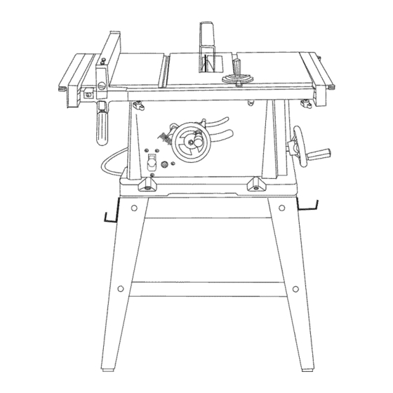
10 in. TABLE SAW WiTH STAND
Model No, 137.218030
CAUTION:
Before using this Table Saw,
read this manual and follow
all its Safety Rules and
Operating
instructions
e
Safety Instructions
•
Installation
o
Operation
e
Maintenance
•
Parts List
Customer
Help Line
For Technical
Support
1-800-843-1682
Sears
Parts
&
Repair
Center
1-800-488-1222
Sears, Roebuck
and Co., Hoffman
Estates,
IL 60179 USA
Visit our Craftsman
website:
www.sears.comlcraftsman
Part No. 137218030001
Advertisement
Table of Contents

Related Manuals for Craftsman 137.218030


Summary of Contents for Craftsman 137.218030
- Page 1 Operator's Manual 10 in. TABLE SAW WiTH STAND Model No, 137.218030 CAUTION: Before using this Table Saw, read this manual and follow all its Safety Rules and Operating instructions Customer Help Line For Technical Support 1-800-843-1682 Sears, Roebuck and Co., Hoffman...
- Page 2 Tools Needed For Assembly ... Carton Contents ... ONE=YEAR if this Craftsman tool fails due to a defect in material or workmanship within one year from the date of purchase, CALL 1-800-4-MY-HOME® TO ARRANGE if this tool is used for commercial or rental purposes, this warranty will apply for only ninety days from the date of purchase.
- Page 3 GENERAL SAFETY iNSTRUCTiONS Read and understand all the instructions below before using the power tool. These safety instructions are not meant to cover every possible condition that could occur. As with any power tool, common sense, vigilance and due care must be used. READ and become familiar with this entire Operator's Manual.
- Page 4 NEVER USE THE MITER GAUGE AND FENCE SIMULTANEOUSLY. NEVER STAND or have any part of your body in line with the path of the saw blade. Keep your hands out of the saw blade path. NEVER REACH behind or over the cutting tool for any reason.
- Page 5 GROUNDING iNSTRUCTiONS tN THE EVENT OF A MALFUNCTION OR BREAKDOWN, grounding provides a path of least resistance for electric currents and reduces the risk of electric shock. This tool is equipped with an electrical cord that has an equipment-grounding and a grounding plug. The plug must be plugged into a matching receptacle that is properly installed and grounded in accordance with all local codes and ordinances.
- Page 6 RECOMMENDED ACCESSORIES WARNING Visit your Sears Hardware Department Craftsman Power and Hand Tools Catalog to purchase recommended accessories for this power tool. [A WARNING To avoid the risk of personal injury: • Do not use adjustable (wobble) type dadoes or carbide tipped dado blades.
- Page 7 UNPACKING YOUR TABLE...
- Page 8 Rip fence Left extension fence Blade tilt pointer Blade tilt scale ON/OFF switch with safety key Overload reset switch Miter gauge storage Front stand mounting holes Blade Blade wrenches Blade guard Miter gauge Table insert Rear mounting holes Side table extension Table Right extension fence Extension fence lock knob...
- Page 9 - Cutting with the grain of the wood or along the length of the workpiece. SAW BLADE PATH - The area of the workpiece or table top directly in line with the travel of the blade or the part of the workpiece that will be cut.
- Page 10 Nut must be flush against the bracket (see Fig. A). 6. Tighten all four nuts. 7. Carefully set the saw in its upright position on a clean level surface. NOTE: DO NOT OVER TIGHTEN NUTS HOLDING SAW TO STAND.
- Page 11 Fig. B-f Fig. B-2 MOUNTING SAW ONTO WORK SURFACE (FIG. C) 1. tf the leg set will not be used, the saw must be properly secured to a sturdy workbench using the four mounting holes at the base of the saw.
- Page 12 Fig, H 7. To tighten the arbor nut (5) place the open-end wrench jaws (8) on the fiats of the saw arbor to keep the arbor from turning. (Fig. 1) 8. Place the box-end wrench (9) on the arbor nut (5), and turn clockwise (to the rear of the saw table).
- Page 13 Fig. K Lift blade guard arm (9) up and using a straight edge, align the blade guard and splitter (10) with the saw blade (11 ) (Fig. L). Shift the splitter bracket assembly to right or left until parallel alignment to the blade is achieved.
- Page 14 Loosen the two bolts (3) and lift up on the handle (2). • Hold the fence bracket (4) firmly against the front of the saw table. Move the far end of the fence until it is parallel with the edge of the miter gauge groove.
- Page 15 ADJUSTING THE 90 ° AND 45 ° POSITIVE STOPS (FIG. Q, Q-f, R) Your saw has positive stops that will quickly position the saw blade at 90 ° to the table. Make adjustments only if necessary. 900 (0 °) Stop 1.
- Page 16 (Fig. T). Fig. T FRONT 4. While standing at the rear of the saw, use a medium size flat blade screwdriver and gently pry the rear of the blade alignment rod to the RIGHT or LEFT.
- Page 17 ON/OFF SWITCH (FIG. V) The on/off switch (1) is located on the front panel of the saw base. To turn the saw ON, move the switch to the up position. To turn the saw OFF, move the switch to the down position.
- Page 18 3. Place the workpiece flat on the table and against the fence. Keep the workpiece about 1 in. away from the blade. 4. Turn the saw ON and wait for the blade to come up to speed. 5. Slowly feed the workpiece into the blade. To feed...
- Page 19 Move the workpiece to one inch distance from the blade. 4. Start the saw and wait for the blade (1) to come up to full speed. Never stand directly in line of the saw blade path, but always stand to the side of the blade that you are cutting on.
- Page 20 IA WARNlaG ABRASIVE AND METAL CUTTING BLADES MUST NOT BE USED WiTH THIS SAW This saw was not made to cut metals or masonry materials. Doing so may result in injury, tt will also void the warranty. USING WOOD FACING ON THE RiP FENCE...
- Page 21 Blade/chippers must not exceed Y2in. total in width. Check saw to ensure that the dado will not strike the housing, insert, or motor when in operation. [AwaRmnGI For your own safety, always replace the blade,...
- Page 22 1. Clean out all sawdust that has accumulated inside the saw cabinet and the motor. 2. Polish the saw table with an automotive wax to keep it clean and to make it easier to slide the workpiece. 3. Clean cutting blades with pitch and gum remover.
- Page 23 Align splitter with blade. Install and use rip fence. Install and use splitter. (with guard) Replace blade. Push material all the way past saw blade before releasing work. Tighten knob. Brush or blow out loose dust and dirt. Replace with adequate size cord.
- Page 24 10 in. TABLE [A WARNING When servicing use only CRAFTSMAN or cause product damage. Any attempt to repair or replace electrical HAZARD unless repair is done by a qualified Sears Service Center, PARTS LIST FOR TABLE SAW SCHEMATIC I. D,...
- Page 25 10 in. TABLE SCHEMATIC 0LMG 2F96 OGIU4 0B3R 0K25 267K2 KCY4 0J764 0B2C OKA4 2 O JET 0B9M6 0J9H oBgc _OKRQs )KMS < OKJO_ OJED "_'J 2"_NJ.B OBAT MODEL NO. 137.218030 27X7 2FGZ 0J76 _0BPA _,OSTQ OKQJ OSGC OKMR OKRX 0B99...
- Page 26 0R20 BAFFLE 2DE1 BRACKET 2DW3 RETAINING CLIP 2EJQ CUTTERSHAFT ASS'Y 2EZY FIELD ASS'Y 2EJQ FOR MOTOR 0R1Y 0R20 0KCP2 0K712 OHX9 h 2DE1 MODEL NO. 137.218030 Size M5"0.8-8 M5"0.8-30 M5"0.8-8 M5"12-60 0QR02 2EZY OQQT2 0R1S 0QM22 0R1Q 0QE9 0KTH 0K3A4...
- Page 27 CAP HD. SO.NECK BOLT 2AJU 2FOZ SHORT UPPER SUPPORT 2F10 LONG UPPER SUPPORT 2FD3 HARDWARE BAG ASS'Y 2GJF HOOK FOR STAND MODEL NO. 137.218030 Size q_SX16-2.5 q_] 0X20-2 M6'1.0-12 MS* 1.25-30 M10"1.5-20 M10"1.5 T=8 M6* 1.0 T=6 M8* 1.25 T=7.5 M8* 1.25-12 2GJF...
- Page 28 PUSH STICK CONSTRUCTION This is a full-size drawing (actual size) Use good quality plywood or solid wood Use 1/2 in. or 3/4 in. material Push stick MUST be thinner than the width of material being cut Cut Here To Push 1/2 in. Wood Cut Here To Push 3/4 in.
- Page 30 For repair - in your home - of all major brand appliances, lawn and garden equipment, no matter who made it, no matter who sold itt For the replacement owner's manuals that you need to do-it-yourself. For Sears professional and items like garage door openers and water heaters. 1-800-4-1VlY-HOIVlE ®...