Table of Contents
Advertisement
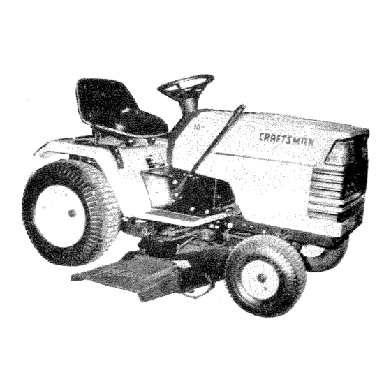
OWNER'S
MANUAL
MODEL NO.
917.254450
AND
917.250020
WITHOUT
MOWER
DECK
CautiGn:
Read
and follow
all Safety
Rules
and instructions
Before
Operating
This Equipment
®
18.0
P TWI
IC
ELECTRIC START
44"MOWER DECK
6
PE
TRANSAXLE
GA
TRACTO
•
Assembly
•
Operation
•
Maintenance
.
Service and Adjustment
•
Repair Parts
Sears, Roebuck and Co., Chicago, iL _684
U.S.A.
Advertisement
Table of Contents

Related Manuals for Craftsman 917.254450


Summary of Contents for Craftsman 917.254450
- Page 1 OWNER'S MANUAL MODEL NO. 917.254450 917.250020 WITHOUT MOWER DECK ® CautiGn: 18.0 P TWI Read and follow all Safety Rules ELECTRIC START and instructions Before Operating 44"MOWER DECK This Equipment TRANSAXLE TRACTO • Assembly • Operation • Maintenance Service and Adjustment •...
- Page 2 CAUTION: LOOK FOR THIS WORD TO POINT OUT _MPORTANT EQUIPMENT PRECAUTIONS, NOTE: LOOK FOR THIS WORD TO POINT OUT IM- PORTANT _NFORMATION ABOUT THE OPERATION AND PERFORMANCE OF YOUR TRACTOR. RULES FOR SAFE OPERATION WARNING: This unit Js equipped with an internal combustion engine and should not be used on or near any unimproved forest covered, brush covered or grass covered land unless the engine s exhaust system is equipped with a spark attester meetingapplicable local or area laws (if any).
- Page 3 CONGRATULATIONS on your purchase of a Sears Garden Tractor. It has been designed, engineered and SERIAL manufactured to give you the best possible dependabilFty NUMBER and performance. Should you experience any problem YsOU cannot easily remedy, please contact your nearest ears Service Department.
- Page 4 iNDEX Tractor Operation on Hills ..t4 Adjustments: Filter: Options: Brake ........Air Cleaner ......Spark Arrestor ....2, 32 Carburetor ......20 Fuel ........Attachments 48-49 Mower Fuel'. Front- To-Rear ....22 Type ........Side- To-Side ..... 21 Storage ........Height .......
- Page 5 ASSEMBLY KNOW YOUR TRACTOR READ THIS OWNER'S MANUAL REFORE OPERATING YOUR GARDEN TRACTOR. If you understand the machine and its operation, you will achieve efficient and peak performance. While reading the manual, compare the illustrations with your Garden Tractor to familiarize yourself with the location of various controls and adjustments. Study the operating instructions and safety precautions thoroughly to insure proper functioning of your Garden Tractor and to prevent injury to yourself and others.
- Page 6 ASSEMBLY AS3EMBLY PARTS BAG CONTENTS SHOWN FULL SiZE LOCATION BATTERY (2) Wing Nut, 1/4- 20 ® BATTERY (2) Hex Bolt, 1/4 - 20 x 3/4 TERMINALS (2) Lockwasher, 1/4 (2) Washer, 9/32 x 5/8 x 16 Ga. (2) Hex Nut, 1/4 - 20 - zD SEAT (I) Adjustment...
- Page 7 ASSEMBLY To assemble and ao}ust your tractor you will need: Ratchet wrench (2) 7/16" Wrenches (I) 3/4" Wrench Tire Pressure Gauge Screwdriver •(1) 9/16" Wrench (I) !/2" Wrench Utility Knife (1) 3/4" Socket NOTE: RIGHT HAND (R.H.) AND LEFT HAND (L.H.) ARE DETERMINED FROM OPERATOR'S POSITION...
- Page 8 Install Steering Wheel NOTE: POSITION FRONT WHEEL FORWARD. a, Use a 3/4" wrench to remove lock nut, 2 ,. 1/4" diameter washer (shown full size below) STEERING WHEEL from steering column (Fig. 3). LOCK 2 , '1/4" DIA. WASHER STEER|NG WHEEL ____Jr-_ _-3,_--_,¢, Position steering wheel over steering wheel insert (Fig,...
- Page 9 A SSEIVIBL Y e. Connect battery cable to positive battery terminal with bolt, flat vcasher, Iockwasher and hex nut (shown full size below) found in bag of parts (Fig. 5). Tighten securely, f, Connect BLACK ground cable to negative battery terminal with remaining...
- Page 10 6. Mower and Drive Bell tnstal/at_n iNSTALL MOWER PARALLEL LiNK Yourtractor has been shipped with the mower parallel link includedin the parts carton. Install mower parallel link on tractor (Fig. 7) usinghinge pin and retainer spring. NOTE: SMALLER END OF PARALLEL LiNK MOUNTS TO TRACTOR.
- Page 11 OPERATION READ THIS OWNER'S MANUAL BEFORE OPERATING YOUR GARDEN TRACTOR. ff you understand the unit and its operation, you will achieve efficient and peak performance. While reading the manual, compare the #lustrations with your Garden Tractor to familiarize yourself with the location of the various controls and adjustments, Study the operating instructions and safety precautions thoroughly to insure proper functioning of your Garden Tractor and to prevent injury to yourseff and others.
- Page 12 OPERA T/ON THIS TRACTOR |S EOUnPPED WITH IN- TERLOCK SWmTCHES PREVENT STARTING OF THE TRACTOR ENGINE _NTAKE •AIR WHILE ATTACHMENT CLUTCH DUCT SWITCH IS JN THE "ENGAGED" POSiTiON AND/OR THE FOOT PEDAL iS NOT FULLY DEPRESSED. iMMEDIATELY REPLACE SWITCHES THAT ARE NOT tN PROPER WORKING ORDER.
- Page 13 OPERA TION NOTE: ALLOW ENGINE TO WARM UP FOR A O_rating Your Tractor and Mower FEW MINUTES BEFORE ENGAGING CLUTCH NOTE: THiS TRACTOR IS EQUIPPED WITH AN OPERA- TRACTOR OR ATTACHMENT- PRESENCE SENSING SWITCH. ATTEMPT When restarting a warm engine, move throttle BY THE OPERATOR...
- Page 14 Drive so that clippings are discharged onto the area that has been cut, Have the cut area to the r_qht of the machine. This will result in a more even distri- bution of clippings and more uniform cutting, When mo wing large areas (Fig...
- Page 15 MAIN To keep your tractor running better, ronger, perform necessary service using _he following maintenance schedule: BEFORE MAKING INSPECTION, JUSTMENT OR REPAJR: PUSH TRACTOR CLUTCHtBRAKE PEDAL COMPLETELY INTO BRAKE POSITION, MOVE GEAR SHIFT LEVER "NEU- TRAL" POSITION. PLACE PARKING 8RAKE IN "ENGAGED POSITION, REMOVE...
- Page 16 Every Hours (T_#ce a Mow#ng SeasonJ f. Bmk_ Adjustmsnt This Tractor is equipped with an adjustable brake system mounted on the right side of the transaxte (Fig. 20). !_T}STOPPING DUS- T_ItGHEST GEAR, THEN Depress clutch/brake pedal and engage parking brake. Measure distance between brake operating arm and nut "A"...
- Page 17 INTENANCE Every 50 Hours (Once. Mo_ing So,son) CUT AWAY VIEW (Operating in dusty conditions may require more frequent servicing. 1, Check Bat:tery VENT CAP Battery acid level each battery cell should be even with bottoms of tubes in ceils {Fig, BATTERY 221.
- Page 18 7. CJean Air Screen Air screen (Fig. 25) must allow free-flow of air to prevent engine damage from overheating, Clean with a wire brush, compressed air or water pressure to remove dirt, chaff, stubborn dried gum and fibers, ALWAYS WEAR SAFETY GLASSES WHEN...
- Page 19 INTENANCE Lubrication .--SPINDLE SPINDLE "qr WHEEL BEARINGS --_-_----- WH E E L BEARINGS_ ENGINE SAE MOTOR EXTREME PRESSURE LUBRICATING GREASE '_3) REFER TO ENGINE SPEC'S IUNDER INITIAL PREPARATION IN OWNERSMANUAL1 REPAIR & ADJUSTMENT ADJUSTMENTS, INSPECTION OR MAINTENANCE: PUSH TRACTOR CLUTCH_BRAKE PEDAL COMPLETELY INTO...
- Page 20 REPAIR & ADJUSTMENTS I. Starting your Tractor With a Weak Battery LEAD-ACID BA'TTERIES GENERATE tf your battery is too weak to start the engine, it should be FLAME SMOKING MATER!_ALS recharged. If 'Jumper cables" are used for emergenc_ E×PLOS_VE GASES. KEEP SPARKS, AWAY...
- Page 21 d, Hold governorcontrol leveragainstidle speed screw, and adjust idle speedscrewto obtain 1200to 1400RPM(Fig.29). e. Whilestill holding the governorcontrol lever against idle speed screw, turn idle mixture valve slowly clockwise (lean mixture) until speed just starts to slow. Turn idle mixture valve back to the midpoint between rich and lean.
- Page 22 REPAIR & ADJUSTMENT If distance "A" needs to be changed, snap out access hote cover on L.H. side above footrest, Use tl/16" wrench on nuts "B" and "C" at side-to-side adjustment trunnion (Fig. 35). To raise left side of mower, loosen nut "B" and tighten nut "C".
- Page 23 ADJUS 7o Mower Retrieval Remove mower dfive be#. (See "MOWER DRtVE BEL T REMOVAL," page 22, through slop 3.) Pull bel_ off engine pulley (Fig. 39), Pull retainer spdngs out of rear suspension trunnions. Remove rear suspension trunnions from lift brackets (Fig.
- Page 24 & FRAME 9. Motion Drfve Bait Rept,_coment NOTE: BELT INSTALLATION DECAL iS LOCATED UNDER LEFT FOOTREST. Remove mower (see "MOWER REMOVAL" page23). Usinga 1/2"wrench, removethectutchlecater (Fig,43), Using a 9116" wrench, l_sen the right hand be# keeper (Fig, 43). Disconnect clutch wire connector.
- Page 25 ADJUSTMENT I-_--'. SEATED, OVER iNFLATiON WHEN MOUNTING TIRES, UNLESS BEADS CAUSE AN EXPLOSION, 12. Rear Wheel Repla¢ement For rear wheel replacement, follow instructions under "TIRE CARE, "page 24. Coat axle with grease to prevent corrosion or rust accumulation and eventual seizing of wheel hub to axle sha& WHEN REPLACING WHEELS...
- Page 26 TROUBLESHOOTING PROBLEM CAUSE / REMEDY (SEE iNDEX} Fill Tank with Gasoline. Check Fuel Line and Carburetor (clean if necessary), Replace Fuel Filter. Use Fresh Fuel WiLL NOT START Recharge or replace Battery Check Wiring Replace Spark Plug(s) and adjust gap Drain and replace oit for proper...
- Page 27 TROUBLESHO0 Move Throttle Control to "FAST" Check air pressure in Tires Check front-to-rear and side-to-side Mower adjustment Use a slower ground speed UNSATISFACTORY MOWER PERFORMANCE Replace Mo wet Blades UNEVEN DISTRIBUTION OF CLIPPINGS Reinstall Mower Blades with Top of Blade Clean underside of Mower Deck...
- Page 28 18 HP GARDEN TRACTOR - - MODEL NUMBER 917.254450 & 917.250020 SCHEMATIC BLACK [" TILLER POWER ATTACHMENT CONNECTOR TAKEOFF _)" CLUTCH!BRAKE L ..{PEDAL SOLENOID 2 TURNS CLOCKWISE t f'_ "_RED CLUTCH "_-- FROM FUSE AMMETER BLACK SEAT SWITCH WHITE BLACK fGNtTIQN (NOT OCCUPIED)
- Page 29 REPAIR PARTS - = MODEL NUMBER 917,254450 & 917°250020 18 HP GARDEN TRACTOR To Engine NOTE: AII component dimensions given in U.S. inches. 1 inch = 25.4 ram. KEY PART KEY PART DESCRIPTtON NO. NO. NO. NO. Screw- Tap. Flex Hd. No. !0 - STD601005"...
- Page 30 REPAIR PARTS 18 HP GARDEN TRACTOR - - MODEL NUMBER 9!7=254450 & 917.250020 CHASSIS ENCLOSURES 95 //_...
- Page 31 REPAIR PARTS 18 HP GARDEN TRACTOR ° = MODEL NUMBER 917.254450 & 9!7o250020 CHASSIS AND ENCLOSURES NOTE: All component dimensions given in U.S. inches- 1 inch = 25.4 mm DESCRIPTION PART PART DESCRIPTION 121248X Bushing, Snap 120066X Seat 12 t249)( Spacer, Split 121294X...
- Page 32 REPAIR PARTS 18 HP GARDEN TRACTOR - = MODEL NUMBER 917.254450 & 917.250020 DRIVE...
- Page 33 REPAIR PARTS 18 HP GARDEN TRACTOR ,. - MODEL NUMBER 917,254450 & 917.250020 DR_VE KEY PART DESCRIPTION KEY PART DESCRIPTION NO. NO, NO. NO, 121327X Pulley, Transaxle (Driven) 123766X Pulley, idler 12000004 Ring, Retainer 123789X Arm, ldtar 2228M Key, Weodruff 4'9 123205X Retainer, Belt 1232"97>(...
- Page 34 REPAIR PARTS 18 HP GARDEN TRACTOR - = MODEL NUMBER 917.254450 & 917,250020 STEERING ASSEMBLY •...
- Page 35 REPAIR PARTS 18 HP GARDEN TRACTOR = = MODEL NUMBER 917.254450 & 917.250020 STEERmNG ASSEMBLY. PART DESCRIPTION PART DESCRtPTION 105810X Decal - Cap, Steemng Wheel 73901000 Nut, Lock, Flange 5/8- ! 1 !007 IOL Insert, Steerinfl Wheel 17490508 Screw, Hex Washer Thd. Roiling 73940800 _Nut, Top Lock 1/2 _20UNF 5/t6- I8 x I,/2...
- Page 36 REPAIR PARTS 18 HP GARDEN TRACTOR - - MODEL NUMBER 917.254450 & 917,250020 ADJUSTMENT " 32 _ __[f" "_" 29...
- Page 37 REPAIR PARTS MOWER18 H P GARDEN TRACTOR ° - MODEL NUMBER 917.254450 " 28 _7"Z...
- Page 38 REPAIR PARTS 18 HP GARDEN TRACTOR - o MODEL NUMBER 917.254450 & 917.250020 LIFT ADJUSTMENT k<EY PART DESCRIPTION KEY PART DESCRIIPTJON NO. NO. 121891X Knob, Depth Adjustment t24516X Shaft- Lift 110807X Nut Hex Special 110448X Link- Lift, Adjust t 10729X Rod - Adjust - Lift 110447X Trunnion-...
- Page 39 REPAIR PARTS 18 HP GARDEN TRACTOR = - MODEL NUMBER 917.254450 MOWER DESCRIPTION KEY PART DESCRiPTiON KEY PART NO. NO. NO, NO. Washer 11/32 x 5/8 x 16 Ga. Nut - LOCk3/8- 19111016 STD541437 19131614 Washer 13/32x 1 x t4 Ga. Decal OPEl ( not serviced) 121316X Rod Hinge...
- Page 40 REPAIR PARTS 18 HP GARDEN TRACTOR - - MODEL NUMBER 917.254450 & 917.250020 TRANSAXLE PEERLESS o - MODEL NUMBER 143-820-016...
- Page 41 REPAIR PARTS !8 HP GARDEN TRACTOR - - MODEL NUMBER 917.254450 & 917o250020 TRANSAXLE PEERLESS-= MODEL NUMBER 143-820-e16 Part Ref. Part Part Name Pa_ Name 7700_ Case, Transaxle 788131 Cap, Bearing 778253 Gear, Spur (15 teeth) 7887_ Washer, Flat 778211 Gear, Spur (12 teeth) 772O98 Cover,...
- Page 42 REPAIR PARTS 18 HP GARDEN TRACTOR - - MODEL NUMBER 917.254450 & 917.250020 ENGINE BRIGGS AND STRATTON - MODEL NUMBER 422707, TYPE NUMBER 1228-01 CYLINDER, CRANKSHAFT AND ENGINE _ASE GROUP //t8...
- Page 43 : EPAIR PARTS 18 HP GARDEN TRACTOR ° - MODEL NUMBER 917.254450 & 917.250020 _NGINE BRIGGS AND STRATTON = MODEL NUMBER 422707, TYPE NUMBER 1228=01 CYLINDER, CRANKSHAFT AND ENGINE BASE GROUP PART DESCRIPTION PART DESCRIPTION 90576 222698 Nut - Flex 8 - 32 Key- Flywheel 89838...
- Page 44 REPAIR PARTS 18 HP GARDEN TRACTOR = = MODEL NUMBER 917.254450 & 917.250020 ENGINE BRIGGS AND STRATTON = MODEL NUMBER 422707, TYPE NUMBER 1228o01 AIR CLEANER - CARBURETOR GROUP...
- Page 45 EPAIR PARTS t 8 HP GARDEN TRACTOR - = MODEL NUMBER 917.254450 & 917.250020 _NGINE BRiGGS AND STRATTON = MODEL NUMBER 422707, TYPE NUMBER 1228-01 #,tR CLEANER - CARBURETOR GROUP PART DESCRIPTION PART DESCRIPTION 212706 Knob _Air Cleaner 262683 Link - Governor 94289 -/Vex...
- Page 46 REPAIR PARTS 18 HP GARDEN TRACTOR - ° MODEL NUMBER 917o254450 & 917o250020 ENGINE BRIGGS AND STRATTON - MODEL NUMBER 422707, TYPE NUMBER 1228=01 ALTERNATOR AND STARTER MOTOR GROUP...
- Page 47 EPAJR PARTS 18 HP GARDEN TRACTOR - - MODEL NUMBER 917.254450 & 917.250020 _GINE BRIGGS AND STRATTON = MODEL NUMBER 422707, TYPE NUMBER 1228-01 LTERNATOR AND STARTER MOTOR GROUP PART DESCRiPTiON PART DESCRIPTION Cover - Air Guide Screw- Sere 222848 94326 Motor.
- Page 48 AHachments That Add to the Usefulness of Your Craftsman Garden Tractor Sears offers a wide variety of attachments that fit your tractor. Many of these are listed bebw with brief explanations of how they can help you. This list was current at the time of publication: however, it may change in future years -- more...
- Page 49 NOWTHROWER has 40-inch swath. Drum-type auger handles powdery and wet/heavy snow. Mounts easiIy with mple pin arangement. Discharge chute adjusts to 240 degree arc from tractor seat. 6-inch diameter spout discharges mow t0 to 50 ft. L#t controlled at tractor seat. (Use with tire chains, wheel weights, or rear drawbar weighb. Stock No. '1-24077, iRE CHAINS are heavy du_;...
- Page 50 SERVICE NOTES...
- Page 51 SUGGESTED GUJOE FOR SiGHTiNG SLOPES FOR SAFE OPERATmON ONLY RIDE UP AND DOWN HILL, NOT ACROSS HiLL SIGHT AND HOLD TH_S LEVEL WITH SKY LINE OR TREE. t5 ° MAX.
- Page 52 I::1# ® OWNER'S 18.0 P TWi MANUAL ELECTRIC START 44"MOWER DECK 6 SPEE TRANSAXLE GARDE TRACTO MODEL NO. 917,254450 Each Tractor has its own model number. Each Engine has its own 917.250020 model number. WITHOUT MOWER DECK The model number for your Tractor will be found on the Model Plate }ocatod under the seat.