Table of Contents
Advertisement
Available languages
Available languages
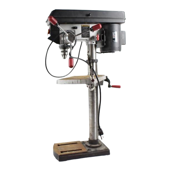
Owner's Manual
CRRFTSMRN °
Bench Model
2/3 HP(Maximum
Developed)
5 Speeds (540-3600 R,P.M.)
1/2 Inch Chuck
12-INCH DRILL PRESS
Model No.
137.219120
CAUTION:
Before using this Drill Press,
read this manual and follow
all its Safety Rules and
Operating Instructions.
• Safety Instructions
• Installation
• Operation
• Maintenance
• Parts List
• Espa_ol
Customer
Help
Line
1.800-843-1682
Sears, Roebuck
and Co., Hoffman
Estates,
IL 60179
USA
Part No.137219120001
Advertisement
Table of Contents

Related Manuals for Craftsman 137.219120


Summary of Contents for Craftsman 137.219120
- Page 1 Owner's Manual CRRFTSMRN ° Bench Model 2/3 HP(Maximum Developed) 5 Speeds (540-3600 R,P.M.) 1/2 Inch Chuck 12-INCH DRILL PRESS Model No. 137.219120 • Safety Instructions CAUTION: • Installation Before using this Drill Press, read this manual and follow • Operation •...
- Page 2 SECTION PAGE Warranty ......°.,o.,o,,°,..=,,,,=, °n =°oJl°°l° Product Specifications ....ooo,.oooo°o,.,,o°,o °° °°°°=l =° Safety Instructions ....°o°oo.o.o°°°.°°o°°°o °° OI°°°Q °° Accessories and Attachments ..,°°o°oo°°°,°o,°o,Jo° °° =°_=° °l Carton Contents ..... °,6 °oo°,°°°°o.oo°o°o,°o °° °°=°° Know Your Drill Press ....o°o°°oo°°°,°..oo°,l, °°...
- Page 3 GENERAL SAFETY INSTRUCTIONS REMOVE ADJUSTING KEYS AND WRENCHES. From the habit of checking to see that keys and BEFORE USING THE DRILL PRESS adjusting wrenches are removed from the tool before turning "ON". Safety is a combination of common sense, staying alert and knowing how to use your drill press.
- Page 4 SPECIFIC SAFETY INSTRUCTIONS SECURE WORK. Use clamps or a vise to hold the FOR THE DRILL PRESS work when practical. It's safer than using your hand and it frees both hands to operate tool. WHEN using a drill press vise, always fasten to the table.
- Page 5 GROUNDINGINSTRUCTIONS This tool is intended for use on a circuit that has a receptacle like the one illustrated in FIGURE A. INTHE EVENT OF A MALFUNCTION OR BREAKDOWN, FIGURE A shows a 3-prong electrical plug and receptacle that has a grounding conductor. If a properly grounded grounding provides a path of least resistance for electric current and reduces the risk of electric shock.
- Page 6 AVAILABLE ACCESSORIES UNPACKING AND CHECKING CONTENTS T!Ylv/_,1 t,:l_ll _ , [ _ Use only accessories recommended for this drill press. If any part is missing or damaged, do not plug the drill Follow instructions that accompany accessories. Use of press in until the missing or damaged part is replaced, improper accessories may cause hazards.
- Page 8 Spindle Motor pulley pulley Depth scale stop nuts Depth scale pointer Cord clamp Belt , rod tension knob Head lock Feed spring Depth stop Cover screw Column collar Bevel scale Table support Head lock screw Bevel lock Support lock handle Base ----_Table crank...
- Page 9 BASE- Supports the drill press. For additional stability, DRILL ON/OFF SWITCH - Has locking feature. This feature is intended to help prevent unauthorized and holes are provided in the base to bolt the drill press to the floor. (See "Specific Safety Instructions for Drill Presses".) possible hazardous use by children and others.
- Page 10 ASSEMBLY INSTRUCTIONS TABLE TO COLUMN ASSEMBLY (FIG. B THROUGH F) Locate the worm gear, table crank, and table support lock handle from the loose parts bag. Insert the worm gear (1) into the table crank handle For your own safety, never connect plug to power source hole (2) from inside the table support (3).
- Page 11 Install the table crank handle (9) to the worm gear Slide the table support assembly with the rack (3,5) shaft (1) on the side of the table support (3). together onto the column. Line up the fiat side of the shaft with the set screw (10) Engage the bottom of the rack (6) with the lip of the column support (6).
- Page 12 INSTALLING FEEDHANDLES (FIG.H) Using a rubber mallet, plastic-tipped hammer, or a Locate three feed handles in the loose parts bag. block of wood and a hammer, firmly tap the chuck Screw the feed handles (1) into the threaded holes (2) upward into position on the spindle shaft.
- Page 13 ADJUSTMENT INSTRUCTIONS FENCE ASSEMBLY (RG, M) Determine the desired location for the fence (1). CAUTION: All the adjustments for the operation of the Align the mounting holes of the fence over the table drill press have been completed at the factory. Due to top slots.
- Page 14 To return the table to its original position, loosen the bevel locking bolt (5). Realign the bevel scale (6) to To prevent personal injury,always disconnect the plug from the 0_ position. the power source when making any adjustments. Return nut (4) on locking pin to the OUTSIDE END OF THREADS.
- Page 15 QUILL RETURN SPRING (FIG. Q, R) _vlvl-1_l L'ql_( The quillreturn spring may need adjustment if the tension To avoid injury from an accidental start, ALWAYS make causes the quill to return too rapidly or too slowly, 1. Lower the table for additional clearance. sure the switch is in the =OFF"...
- Page 16 BASIC DRILL PRESS OPERATIONS Fig. U SPEEDS AND BELT PLACEMENT (FIG. T) This drill press has 5 speeds, as listed below: 1600RPM 2610 RPM 3600 RPM See inside of the belt guard for specific placement of the belts on the pulleys to change speeds. To avoid possible injury, keep guard closed, in place, and in proper working order while tool is in operation.
- Page 17 Fig. X To prevent the workpiece or backup material from being torn from your hands while drilling,you MUST positionthe workpiece against the LEFT side of the column. If the workpiece or the backup material is not long enough to reach the column, clamp them to the table, or use the fence provided with the drill press to brace the workpiece.
- Page 18 REMOVING CHUCK (FIG. Z) b. Whenever possible, position the WORKPIECE to With the switch =OFF", open the jaws of the chuck as contact the left side of the column.If it is too short wide as possible by turningthe chuck counterclockwise. or the table is tilted, use the fence provided or Tap the chuck (1) lightly with a plastic tipped hammer clamp solidly to the table, using the table slots.
- Page 19 POSITIONING THE TABLE AND WORKPIECE HOLDING A DRILLING LOCATION (FIGURE AA and BB) Using a centerpunch or sharp nail, make an Lock the table (1) to the column (2) at a position so indentation in the workplace where you want the hole. the tip of the dnll bit (3) is Justabove the top of the Using the feed handles, bring the drill down to align workpiece (4).
- Page 20 MAINTAINING YOUR DRILL PRESS To avoid shock or fire hazard, if the power cord is worn or cut in any way, have it replaced immediately. For your own safety, turn the switch OFF and remove the plug from the power source outlet before maintaining or LUBRICATION lubricating your drill press.
- Page 21 TROUBLESHOOTING GUIDE To avoid, injury from an accidental start, turn the switch OFF and always remove the plug from the power source before making any adjustments. • Consult your local Sears Service Center if for any reason the motor will not run. PROBLEM PROBABLE CAUSE REMEDY...
- Page 22 MODEL NO, 137.2191,20 When servicing use only CRAFTSMAN replacement parts. Use of any other parts may create a HAZARD or cause product damage. Any attempt to repair or replace electrical parts on this Table Saw may create a HAZARD unless repair is done by a qualified service technician.
- Page 23 CRAFTSMAN12" DRILL PRESS MODEL NO. 137.219120 SCHEMATIC "gA...
- Page 24 CRAFTSMAN 12" DRILL PRESS MODEL NO. 137.219120 PARTS LIST FOR SCHEMATIC B S ize Kf0y Description Part 10518401 M1Ox1.5 10301004 SET BOLT 10201201 POINTER 2135CNO132 CHUCK ASS'Y 10305602A1 QUILL ASS'Y 2701FBD106 HEX NUT M6X1,0 10361701 SET RING 2602BBLA27 HEX. SOC. HD,CAP BOLT M5 x 0.8-16...
- Page 25 CRAFTSMAN12" DRILL PRESS MODEL NO. 137.219120 SCHEMATIC...
- Page 26 MODEL NO. 137.2t912C CRAFTSMAN 12" DRILL PRESS PARTS UST FOR SCHEMATIC C Size Description Part 2138MBL704 WRENCH HEX 4-64 2138MBL703 WRENCH HEX 3-57 2807BY06H2 POWER CABLE 13916905 LABEL 2801ABRF04 STRAIN RELIEF 2572ARK340 V-BELT 10306901 PULLEY SET NUT 10307005 SPINDLE PULLEY...
- Page 27 MODEI.NO. 137.219120 CRAFTSMAN12" DRILL.PRESS SCHEMATIC...
- Page 28 For repair of major brand appliances in your own home... no matter who made it, no matter who sold it! 1,800-4-MY-HOME s" Anytime, day or night (1-800-469-4663) www.sears.com To bring in products such as vacuums, lawn equipment and electronics for rePair, cell for the location of your nearest Sears Parts & Repair Center 1.800-488-1222 dayor n _ht www.sears.com...
- Page 29 Manual de Operacibn CRRFTSMRN ° 2/3HP (Potencia M_xima) 5 Velocidades (540-3600 R.P.M.) Mandril de 1/2 Pulg. PRENSA TALADRADORA DE 12 PULG. Modelo No. 137,219120 CUIDADO: Instrucciones de Seguridad Instalaci6n Antes de usar esta Prensa Taladradora leer este manual Operaci6n y seguir todas las Reglas de Mantenimiento Seguridad e instrucciones Lista de Partes...
- Page 30 SECCION PAGINA Garantia ................Especificaciones de la Herramienta ............Instrucciones de Seguridad ............Accesorios y Aditamentos ............. Contenido de la Caja ..............Familiarizarse con la Prensa Taladradora ..........Glosario de Terminos ..............Ensamblaje y Regulacibn .............. Operaci6n ..............)..Mantenimiento ..............
- Page 31 14. RETIRAR LAS HERRAMIENTAS INSTRUCCIONES GENERALES DE REGULACI6N. Formarse el habitode verificar q ua las SEGURIDAD herramientasy lasIlavesde regulaci6n hayansidoretirades del taladroantesde activado. ANTES DE USARLAPRENSATALADRADORA NUNCA DEJAR DESATENDIDAUNA HERRAMIENTA La seguridad es una combinaci6n de sentido comdn, mantenerse ELI_CTRICACUANDO ESTE FUNCIONANDO. alerta y saber como usar la PrensaTaladradora.
- Page 32 REGLASDE SEGURIDADESPEC{FICAS RJAR LA PIEZA DE TRABAJO.Cuandofuesaprdctico, usarsargentas o una prensapara sujetar1_piezade tmbajo. PARALA PRENSATALADRADORA Es rods saguro que usarla mano y deia librearnbasmanos para operarla hermmienta. AL USAR una prensa para taladro,siempresujetariaa la mesa. Por su propia seguddad, n o ttatar de usar la Prensa Taladradorani enchufarlahasta que est_ completamente-ensamblada e instalada CERCIORARSEQUE todoslos elementosmecdnicos de de acuerdocon las istrucciones,y hasta haber leido y entendido...
- Page 33 INSTRUCCIONES PAPA LA CONEXI(_N A TIERRA Esta herramienta est_ disefiada pera usarseen un cimuito que tengaun tomacorriente c omo el ilustrado en la FIGURAA. La RGURA (A) muestraun enchufe elL_.--trico y un tomacorriente EN EL EVENTO DE UNA FALLAO MAL FUNCIONAMIENTO, d_ 3 contactos, unode los cualeses un conductor pare la conexi6n a tierraproveeuna via de menor resistencia parela conexi6n a tierra.Si no se dispone de un tomacorfiente c on...
- Page 34 DESEMBALAJE Y VERIFICACI6N ACCESORIOS DISPONIBLES CONTENIDO S61o usar accesorios recomendadospara esta Prensa Taladradora Seguir las instruccionesque acompafian a los Si t&itasenpiezas o hubiesen piezasda_adas, no enchufar l a accesoriosEl uso de accesorios inadecuadospuede PrensaTaladradorahasta conseguir l as piezas t<anteso de generar riesgos reemplazar las dafiadas y hasta haber ¢ompletade el ensambt&je Visitarel Departamentode Ferreteda de la tiendaSears...
- Page 36 Poleas de las Correas Tuerca Superior de Tope Aguja de la escala Suletador de profundidad deLCordbn i de Profundidad Manija Tensionadon de tope de avance de Coneas Cubierta Protectora Resorte del Mecanismo Tope de profundidad de Avance la Co|umna Escala de Inclinacibn Soporte de la Mesa Interruptor...
- Page 37 BASE - Soporta VF:LOCIDADDETALADRADO - Se carnbia colosando ta corrsa la PrensaTaladradom. P aramayorestabilidad estdprovista de orificios paraempemar la PrensaTaladradom al encualquierade las poleas.Ver la Tablade Velocidadesen la piso.(Ver"InstnJccionesde SeguridadEspec_'flsas para Prensas parte intema de la cubierta protectorade las correas. Taladradoras').
- Page 38 Ens•mbl•je de la columna • I• meu (Fig. B • F) 1. Ubicarel eje de tomillosinfln,la manivelade la mesay el INSTRUCCIONES PARA EL ENSAMBLAJE segurodelsoportede la mesade la bolsade piezassueltas. 2. Introducir e l eje de tomiUo sinfln(1) en el oriflc_o (2) par• la manivel•de la mesa desdela parte interior d el soporte (3).
- Page 39 5. Colocarla unidadde soportede la mesajuntocon la cremallera 8. Instalela manivela (9) en el eje del tomillosinfln(1) en el ladodel ( 3, 5) en la columna, soportede la mesa (3). 6. Hacerque la parte inferior d e la cremallera(5) encajeen el borde 9. Alineela parte planadel eje con el tom,in pdsionero (10) de la del soporte de la columna(6).
- Page 40 |NSTALACIONDE LAS MANIJAS DE AVANCE(RG.H) Ubicarlastresmanijas de avanceen la boI_. de piezas Usandoun mazo de cauchoo martillo con cabeza de sueltas. pl_co o un bloquede maderay un martil_o, go_peado Insertery enroscar tas manijas(1) en losorificios levementehada arribahastaque enca)eenposicibn en el eje. roscades (2)ctet c ubo(3).AjusWr.
- Page 41 REGULACION DE LA PRENSA TALADRADORA ENSAMBLAJE DE LA GUIA (FIG. M) 1. Decidir cuSI es la posicibn deseada de la gula (1). 2 Alinear los orificios de instalacibn de la gula con las ranuras CUIDADO:T_xloslos ajustesy regulaciones n ecesar_as para la de la parte superior de la mesa.
- Page 42 5. Volvera colocar la tuerca(4) en el pasador de fijadbn,en el EXTREMOEXTERIOR DE LA ROSCA. Golpear auavernerrt_ el Pareevitarlesiones personales, siempredesconectar e l enchufe del tomacorriente a ntesde hasarcuelquier r egulacion. pasador de fijacibnhasteque quedeesentadoen elorificlo. Ajustarla tuerca(4) con losdedos. PARAPONER LA MESA A ESCUADRACON EL CABEZAL NOTA:Pare mayorcladdad,en la ilustracibn nose hainduidola (RG.
- Page 43 tI_IESORTEDE RETORNO DE LA MORTAJA(FIG. Q, R) El resole de retomode la mortajapodriarequenrregulacibn si "S:u tensibrt hace que la mortaja regmsedemasiado _pido o demasiado lento: Para evitar lesiones debidas a un arranqueaccidental, antesde Bajarla mesa para Iograruna mayorsaparaci6n. hacer ajustes alas correas, SlEMPRE cerciorarse que el Colocarun desarmador en la ranura(1) frontal inferior de la interruptor este en la posicion"OFF"(Apagado),que la Ilave del tapa (2) del resorte.
- Page 44 OPERACIONES BASICAS DE LA PRENSA TALADRADORA Fig. U VELOCIDADESY POSICR3NDE LAS CORREAS (FIG. 1") Esta prensatafadradora tiene 5 velocidades comose indica continuaci6n: 1600RPM 2610 RPM 3600 RPM Referirsea la tabla en la parte interior de la cubierta de la correa para obtener la posici6n especfficade las correas en las poleas para cada velocidad.
- Page 45 Fig. X Pare evitarque la piezade trabajoo la materialde apoyose sueltende las manos,se DEBEN posicionar contrael lade IZQUIERDO de la columna. Si la pieza de trabajo o la madera de reepaldo son Io suflcientementelargas como pare alcanzar la columna, prensarlas ala mesa o usar la gula provistacon la Prensa Taladradorapare sujetar el material.No Sujetar la pieza de trabajo puede causar lasiones.
- Page 46 QUITAR EL PORTABROCAS (FIG. Z) 1. Con el interruptor en =OFF" (Apagado), abrir las b) Siempreque sea posible, c otocarLA PIEZADE mandibulas del mandril girando la manga del mandrill TRABAJOde tal maneraque hagacontacto conla parte izquierdadela columna. S ifuese muy cortao si la mesa •...
- Page 47 PARAMANTENER LA BROCA EN LA POSICI(3NDE LA PQSICIONAMIENTODE LA MESAY PIEZA DE TRABAJO PERFORACI(_N !FIGUREA, A arid Be) Usandoun centropunzono clavopuntiagudo,punzarla pieza Asegurar l a rnesa(1) a lacolumca(2) en unaposick_n talque de trabajo en el lugardonde se desaahacer el orfficio. la puntade la broca(3) quedejustosobrela piezade trabajo(4), Antes de hacerfuncionar el taladro,usarlasmanijas de SIEMPRE colocarun MATERIALDE APOYO(maderade...
- Page 48 MANTENIMIENTO DE LA PRENSA TALADRADORA Para evitar los riesgos de choque electricoo incendio, si el cord6n electrico estuviese gastado o cortado, repararlo o cambiado de inmediato. Por su propia seguridad colocar el interruptor en la posici6n LUBRICACI( N "OFF" (Apagado) y desconectar el enchufe del tomacorriente antes de darle mantenimientoo lubncarla PrensaTaladradora.
- Page 49 GU[A PARA DIAGN(3STICO DE PROBLEMAS Paraevitar]esionesocasionadas por un arranque accidental, mover el interruptor a la posici6n de "OFF" (Apagado)y desconectar el cord6n de suministro del toma corrienta antes de hacer cualquier regulacion. Consultar al Centro de Servicio Sears local si el motor no arrancase por cualquier motivo. SOLUCION CAUSA PROBABLE PROBLEMA...
- Page 50 N° 137.219120 AI efectuar el mantenimiento utilice solamente piezas de reemplazo CRAFTSMAN. La utilizaci6n de cualquier otra pieza puede ocasionar PELIGRO o ser la causa de daSos al producto.Cualquier intento de reparar o reemplazar panes electric, as de esta Sierra de mesa puede ocasionar PELIGRO a menos que dicha reparaci6n haya sido hecha por un tecnico calificado de servicio.
- Page 51 NOMENCLATURE DE LA PERCEUSE A COLONNE DE 12 PO MODELE 137.219120 DIAGRAMA A...
- Page 52 NOMENCLATURE DE LA PERCEUSE A COLONNE DE 12 PO MODELE 137.219120 LISTA DE PIEZAS PARA EL DIAGRAMA B No,Diag. No. Parte Descripcion Tamaho Cantidad 10518401 Tuerca M10xl 5 10301004 Perno de Fijaci6n 10201201 Indicador 2135CNO132 Mandrill 10305602A1 Mortaja 2701FBD106 Tuerca Hexagonal M6Xl.0 10361701 Anillo de Sujei6n...
- Page 53 MODI_LE N° 137.219120 NOMENCLATURE DE LA PERCEUSE A COLONNE DE 12 PO DIAGRAMA B...
- Page 54 _IOMENCLATURE DE LA PERCEUSE .&. C OLONNE DE 12 PO MODELE N° 137.219120 LISTA DE PIEZAS PARA EL DIAGRAMA C Tama_o No.Diag. No. Parte Descripcibn Cantidad 2138MBL704 Ltave Hexagonal 2138MBL703 3-57 Llave Hexagonal 2807BY06H2 Cordbn El_ctrico 13916905 Etiqueta 2801ABRF04 Alivio de Tensi6n 2572ARK340 Correa-V 10306901...
- Page 55 MODI_LE N° 137.219120 NOMENCLATURE DE LA PERCEUSE A COLONNE DE 12 PO DIAGRAMA C...
- Page 56 .... For repair of major brand appliances in your own home... no matter who made it, no matter who sold it[ i;_i_ !ili HOME ..:_ _, 1-800-4-MY- SM A._ime. aay or n_.t ,,.::, ..ii_:i: (1-800469-4663) www.sears.com ii_iiiii_ii To bring in products such as vacuums, awn equipment and electronics ;ii;:iiii_ for repa=r, call for the Iocat=on of your nearest Sears Parts &...