Table of Contents
Advertisement
Quick Links
Advertisement
Table of Contents

Related Manuals for Gigabyte GA-G41MT-D3PT


Summary of Contents for Gigabyte GA-G41MT-D3PT
- Page 1 GA-G41MT-D3PT User's Manual Rev. 1301 12ME-41MT3PT-1301R...
-
Page 3: Identifying Motherboard Revision
The trademarks mentioned in this manual are legally registered to their respective owners. Disclaimer Information in this manual is protected by copyright laws and is the property of GIGABYTE. Changes to the specifications and features in this manual may be made by GIGABYTE with- out prior notice. -
Page 4: Table Of Contents
Table of Contents GA-G41MT-D3PT Motherboard Layout ................5 GA-G41MT-D3PT Motherboard Block Diagram ..............6 Chapter 1 Hardware Installation ..................7 Installation Precautions ..................7 Product Specifications ..................8 Installing the CPU and CPU Cooler ............... 10 Installing the Memory ..................11 Installing an Expansion Card ................. 11 Back Panel Connectors .................. -
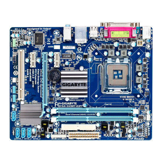
Page 5: Ga-G41Mt-D3Pt Motherboard Layout
GA-G41MT-D3PT Motherboard Layout CPU_FAN KB_MS ATX_12V LGA775 R_USB USB_LAN AUDIO Intel ® PCIEX1_1 Atheros AR8151 B_BIOS M_BIOS CLR_CMOS PCIEX16 IT8718 PCIEX1_2 CODEC Intel ® ICH7 SATA2_3 SATA2_2 SYS_FAN SATA2_1 F_AUDIO F_USB1 F_USB2 SATA2_0 Box Contents GA-G41MT-D3PT motherboard Motherboard driver disk... -
Page 6: Ga-G41Mt-D3Pt Motherboard Block Diagram
GA-G41MT-D3PT Motherboard Block Diagram PCIe CLK CPU CLK+/- LGA775 (100 MHz) (333/266/200 MHz) Host Interface DDR3 1333(O.C.)/1066/800 MHz Dual Channel Memory PCI Express x16 Intel ® MCH CLK 1 PCI Express x16 (333/266/200 MHz) 2 PCI Express x1 Dual BIOS... -
Page 7: Chapter 1 Hardware Installation
Chapter 1 Hardware Installation Installation Precautions The motherboard contains numerous delicate electronic circuits and components which can become damaged as a result of electrostatic discharge (ESD). Prior to installation, carefully read the user's manual and follow these procedures: Prior to installation, do not remove or break motherboard S/N (Serial Number) sticker or •... -
Page 8: Product Specifications
4 GB. Dual channel memory architecture Š Support for DDR3 1333(O.C.)1066/800 MHz memory modules Š (Go to GIGABYTE's website for the latest supported memory speeds and memory modules.) Onboard Integrated in the North Bridge: Š... - Page 9 Support for Microsoft Windows 7/Vista/XP Š ® System Form Factor Micro ATX Form Factor; 24.4cm x 19.4cm Š * GIGABYTE reserves the right to make any changes to the product specifications and product-related information without prior notice. - 9 - Hardware Installation...
-
Page 10: Installing The Cpu And Cpu Cooler
Read the following guidelines before you begin to install the CPU: Make sure that the motherboard supports the CPU. • (Go to GIGABYTE's website for the latest CPU support list.) Always turn off the computer and unplug the power cord from the power outlet before installing •... -
Page 11: Installing The Memory
Make sure that the motherboard supports the memory. It is recommended that memory of the • same capacity, brand, speed, and chips be used. (Go to GIGABYTE's website for the latest supported memory speeds and memory modules.) Always turn off the computer and unplug the power cord from the power outlet before installing •... -
Page 12: Back Panel Connectors
Back Panel Connectors PS/2 Keyboard and PS/2 Mouse Port Use the upper port (green) to connect a PS/2 mouse and the lower port (purple) to connect a PS/2 keyboard. Parallel Port Use the parallel port to connect devices such as a printer, scanner and etc. The parallel port is also called a printer port. -
Page 13: Internal Connectors
Internal Connectors ATX_12V F_AUDIO F_USB1/F_USB2 CPU_FAN SYS_FAN CLR_CMOS SATA2_0/1/2/3 F_PANEL Read the following guidelines before connecting external devices: First make sure your devices are compliant with the connectors you wish to connect. • Before installing the devices, be sure to turn off the devices and your computer. Unplug the •... - Page 14 1/2) ATX_12V/ATX (2x2 12V Power Connector and 2x12 Main Power Connector) With the use of the power connector, the power supply can supply enough stable power to all the com- ponents on the motherboard. Before connecting the power connector, first make sure the power supply is turned off and all devices are properly installed.
-
Page 15: Sata 3Gb/S Connectors
3/4) CPU_FAN/SYS_FAN (Fan Headers) The motherboard has a 4-pin CPU fan header (CPU_FAN) and a 3-pin (SYS_FAN) system fan header. Most fan headers possess a foolproof insertion design. When connecting a fan cable, be sure to connect it in the correct orientation (the black connector wire is the ground wire). The motherboard supports CPU fan speed control, which requires the use of a CPU fan with fan speed control design. -
Page 16: Front Panel Heade
6) F_PANEL (Front Panel Header) Connect the power switch, reset switch, speaker and system status indicator on the chassis front panel to this header according to the pin assignments below. Note the positive and negative pins before con- necting the cables. SPEAK- PWR- Power LED... -
Page 17: Front Panel Audio Header
7) F_AUDIO (Front Panel Audio Header) The front panel audio header supports Intel High Definition audio (HD) and AC'97 audio. You may connect your chassis front panel audio module to this header. Make sure the wire assignments of the module con- nector match the pin assignments of the motherboard header. - Page 18 9) IDE (IDE Connector) The IDE connector supports up to two IDE devices such as hard drives and optical drives. Before attach- ing the IDE cable, locate the foolproof groove on the connector. If you wish to connect two IDE devices, remember to set the jumpers and the cabling according to the role of the IDE devices (for example, master or slave).
-
Page 19: Battery
11) BAT The battery provides power to keep the values (such as BIOS configurations, date, and time information) in the CMOS when the computer is turned off. Replace the battery when the battery voltage drops to a low level, or the CMOS values may not be accurate or may be lost. You may clear the CMOS values by removing the battery: 1. -
Page 20: Chapter 2 Bios Setup
To see more advanced BIOS Setup menu options, you can press <Ctrl> + <F1> in the main menu of the BIOS Setup program. To upgrade the BIOS, use either the GIGABYTE Q-Flash or @BIOS utility. Q-Flash allows the user to quickly and easily upgrade or back up BIOS without entering the operating •... -
Page 21: Mb Intelligent Tweaker(M.i.t.)
If you do not find the settings you want in the Main Menu or a submenu, press <Ctrl>+<F1> to • access more advanced options. When the system is not stable as usual, select the Load Optimized Defaults item to set your •... - Page 22 CMOS Setup Utility-Copyright (C) 1984-2011 Award Software MB Intelligent Tweaker(M.I.T.) Item Help x CAS Latency Time Auto Menu Level x tRCD Auto x tRP Auto x tRAS Auto >>>>> Advanced Timing Control Advanced Timing Control [Press Enter] ******** Mother Board Voltage Control ******** Voltage Types Normal Current...
- Page 23 CPU Host Frequency (Mhz) Allows you to manually set the CPU host frequency. The adjustable range is from 100 MHz to 1200 MHz. This item is configurable only when the CPU Host Clock Control option is enabled. Important: It is highly recommended that the CPU frequency be set in accordance with the CPU specifications.
- Page 24 >>>>> Advanced Timing Control Advanced Timing Control CMOS Setup Utility-Copyright (C) 1984-2011 Award Software Advanced Timing Control Item Help x tRRD Auto Menu Level x tWTR Auto x tWR Auto x tRFC Auto x tRTP Auto x Command Rate (CMD) Auto >>>>>...
- Page 25 Static tRead Value Options are: Auto (default), 1~15. tRD Phase0 Adjustment Options are: Auto (default), 0-Normal, 1-Advanced. tRD Phase1 Adjustment Options are: Auto (default), 0-Normal, 1-Advanced. tRD Phase2 Adjustment Options are: Auto (default), 0-Normal, 1-Advanced. tRD Phase3 Adjustment Options are: Auto (default), 0-Normal, 1-Advanced. Trd2rd(Different Rank) Options are: Auto (default), 1~15.
- Page 26 Channel A/B Driving Settings CMOS Setup Utility-Copyright (C) 1984-2011 Award Software Channel A/B Driving Settings Item Help x Driving Strength Profile Auto Menu Level x Data Driving Pull-Up Level Auto x Cmd Driving Pull-Up Level Auto x Ctrl Driving Pull-Up Level Auto x Clk Driving Pull-Up Level Auto x Data Driving Pull-Down Lev...
-
Page 27: Standard Cmos Features
Standard CMOS Features CMOS Setup Utility-Copyright (C) 1984-2011 Award Software Standard CMOS Features Item Help Date (mm:dd:yy) Fri, Mar 11 2011 Menu Level Time (hh:mm:ss) 22:31:24 IDE Channel 0 Master [None] IDE Channel 0 Slave [None] IDE Channel 2 Master [None] ... -
Page 28: Advanced Bios Features
Advanced BIOS Features CMOS Setup Utility-Copyright (C) 1984-2011 Award Software Advanced BIOS Features Item Help Hard Disk Boot Priority [Press Enter] Menu Level Quick Boot [Disabled] CD/DVD Boot option [Auto] First Boot Device [Hard Disk] Second Boot Device [CDROM] Third Boot Device [Legacy LAN] Password Check... - Page 29 CPU Multi-Threading (Note) Allows you to determine whether to enable all CPU cores and multi-threading function when using an Intel CPU that supports multi-core technology. This feature only works for operating systems that support multi-processor mode. Enabled Enables all CPU cores and multi-threading capability. (Default) Disabled Enables only one CPU core.
-
Page 30: Advanced Chipset Features
Advanced Chipset Features CMOS Setup Utility-Copyright (C) 1984-2011 Award Software Advanced Chipset Features Item Help ** VGA Setting ** Menu Level Onboard VGA [Enable If No Ext PEG] Init Display First [PCI] PAVP Mode [PAVP Lite Mode] PAVP Lite Mode [32MB] x Paranoid PAVP Mode (32+96)128MB... -
Page 31: Integrated Peripherals
Integrated Peripherals CMOS Setup Utility-Copyright (C) 1984-2011 Award Software Integrated Peripherals Item Help On-Chip Primary [Enabled] Menu Level On-Chip SATA Mode [Auto] x PATA IDE Set to Ch.0 Master/Slave SATA Port0/2 Set to Ch.2 Master/Slave SATA Port1/3 Set to Ch.3 Master/Slave Azalia Codec [Auto] Onboard H/W LAN... - Page 32 Onboard H/W LAN Enables or disables the onboard LAN function. (Default: Enabled) If you wish to install a 3rd party add-in network card instead of using the onboard LAN, set this item to Disabled. CMOS Setup Utility-Copyright (C) 1984-2011 Award Software SMART LAN Item Help Start detecting at Port..
-
Page 33: Power Management Setup
Power Management Setup CMOS Setup Utility-Copyright (C) 1984-2011 Award Software Power Management Setup Item Help ACPI Suspend Type [S3(STR)] Menu Level Soft-Off by PWR-BTTN [Instant-Off] PME Event Wake Up [Enabled] Power On by Ring [Enabled] Resume by Alarm [Disabled] Date (of Month) Alarm Everyday Time (hh:mm:ss) Alarm 0 : 0 : 0... - Page 34 HPET Support (Note) Enables or disables High Precision Event Timer (HPET) for Windows 7/Vista operating system. (Default: Enabled) HPET Mode (Note) Allows you to select the HPET mode for your Windows 7/Vista operating system. This item is configu- rable only when the HPET Support is set to Enabled. (Default: 32-bit mode) Power On By Mouse Allows the system to be turned on by a PS/2 mouse wake-up event.
-
Page 35: Pnp/Pci Configurations
2-9 PnP/PCI Configurations CMOS Setup Utility-Copyright (C) 1984-2011 Award Software PnP/PCI Configurations Item Help PCI1 IRQ Assignment [Auto] Menu Level : Move Enter: Select +/-/PU/PD: Value F10: Save ESC: Exit F1: General Help F5: Previous Values F6: Fail-Safe Defaults F7: Optimized Defaults PCI1 IRQ Assignment Auto BIOS auto-assigns IRQ to the first PCI slot. -
Page 36: Load Fail-Safe Defaults
CPU/SYSTEM FAN Fail Warning Allows the system to emit warning sound if the CPU/system fan is not connected or fails. Check the fan condition or fan connection when this occurs. (Default: Disabled) CPU Smart FAN Control Enables or disables the CPU fan speed control function. Enabled allows the CPU fan to run at different speed according to the CPU temperature. -
Page 37: Set Supervisor/User Password
2-13 Set Supervisor/User Password CMOS Setup Utility-Copyright (C) 1984-2011 Award Software CMOS Setup Utility-Copyright (C) 1984-2011 Award Software MB Intelligent Tweaker(M.I.T.) PC Health Status Standard CMOS Features Load Fail-Safe Defaults Advanced BIOS Features Load Optimized Defaults Advanced Chipset Features Set Supervisor Password ... -
Page 38: Exit Without Saving
2-15 Exit Without Saving CMOS Setup Utility-Copyright (C) 1984-2011 Award Software CMOS Setup Utility-Copyright (C) 1984-2011 Award Software MB Intelligent Tweaker(M.I.T.) PC Health Status Standard CMOS Features Load Fail-Safe Defaults Advanced BIOS Features Load Optimized Defaults Quit Without Saving (Y/N)? N Advanced Chipset Features Set Supervisor Password... - Page 39 - 39 - BIOS Setup...
- Page 40 WEB address (English): http://www.gigabyte.com WEB address (Chinese): http://www.gigabyte.tw You may go to the GIGABYTE website, select your language in the language list on the top right corner of the website. • GIGABYTE Global Service System To submit a technical or non-technical (Sales/Market- ing) question, please link to: http://ggts.gigabyte.com.tw...