
Related Manuals for Gigabyte GA-G41MT-D3


Summary of Contents for Gigabyte GA-G41MT-D3
- Page 1 GA-G41MT-D3 GA-G41MT-ES2L LGA775 socket motherboard for Intel Core processor family/ ® ™ Intel Pentium processor family/Intel Celeron processor family ® ® ® ® User's Manual Rev. 1303 12ME-G41MTD3-1303R...
-
Page 3: Identifying Your Motherboard Revision
GIGABYTE's prior written permission. Documentation Classifications In order to assist in the use of this product, GIGABYTE provides the following types of documentations: For detailed product information, carefully read the User's Manual. -
Page 4: Table Of Contents
Table of Contents GA-G41MT-D3/GA-G41MT-ES2L Motherboard Layout ..........5 Chapter 1 Hardware Installation ..................6 Installation Precautions ..................6 Product Specifications ..................7 Installing the CPU and CPU Cooler ..............9 1-3-1 Installing the CPU .....................9 Installing the Memory ..................10 1-4-1 Dual Channel Memory Configuration ..............10 Installing an Expansion Card ................. -
Page 5: Ga-G41Mt-D3/Ga-G41Mt-Es2L Motherboard Layout
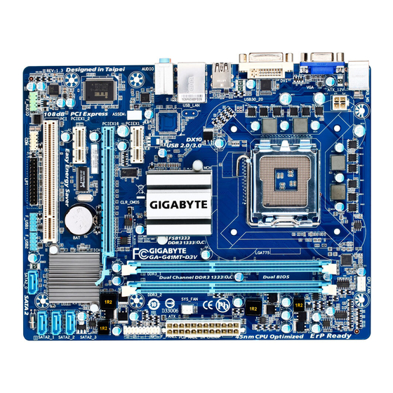
GA-G41MT-D3/GA-G41MT-ES2L Motherboard Layout CPU_FAN KB_MS ATX_12V COMA LGA775 R_USB USB_LAN AUDIO Intel ® F_AUDIO PCIEX1 Realtek RTL8111D/E B_BIOS BATTERY M_BIOS PCIEX16 IT8718 PCI1 CODEC Intel ICH7 PCI2 ® SATA2_3 SATA2_2 F_USB2 SYS_FAN SATA2_1 F_USB1 SATA2_0 "*" The GA-G41MT-D3 adopts All-Solid Capacitor design. Box Contents GA-G41MT-D3 or GA-G41MT-ES2L motherboard Motherboard driver disk... -
Page 6: Chapter 1 Hardware Installation
Chapter 1 Hardware Installation Installation Precautions The motherboard contains numerous delicate electronic circuits and components which can become damaged as a result of electrostatic discharge (ESD). Prior to installation, carefully read the user's manual and follow these procedures: • Prior to installation, do not remove or break motherboard S/N (Serial Number) sticker or warranty sticker provided by your dealer. -
Page 7: Product Specifications
2 x 1.5V DDR3 DIMM sockets supporting up to 4 GB of system memory Dual channel memory architecture Support for DDR3 1066/800 MHz memory modules (Go to GIGABYTE's website for the latest supported memory speeds and memory modules.) Onboard Graphics w Integrated in the North Bridge:... - Page 8 Internal 2 x USB 2.0/1.1 headers Connectors 1 x serial port header 1 x clearing CMOS jumper Back Panel 1 x PS/2 keyboard port Connectors 1 x PS/2 mouse port 1 x parallel port 1 x serial port 1 x D-Sub port w 4 x USB 2.0/1.1 ports 1 x RJ-45 port...
-
Page 9: Installing The Cpu And Cpu Cooler
Read the following guidelines before you begin to install the CPU: • Make sure that the motherboard supports the CPU. (Go to GIGABYTE's website for the latest CPU support list.) • Always turn off the computer and unplug the power cord from the power outlet before installing the CPU to prevent hardware damage. -
Page 10: Installing The Memory
• Make sure that the motherboard supports the memory. It is recommended that memory of the same capacity, brand, speed, and chips be used. (Go to GIGABYTE's website for the latest supported memory speeds and memory modules.) • Always turn off the computer and unplug the power cord from the power outlet before installing the memory to prevent hardware damage. -
Page 11: Back Panel Connectors
Back Panel Connectors PS/2 Keyboard and PS/2 Mouse Port Use the upper port (green) to connect a PS/2 mouse and the lower port (purple) to connect a PS/2 keyboard. Parallel Port Use the parallel port to connect devices such as a printer, scanner and etc. The parallel port is also called a printer port. -
Page 12: Internal Connectors
Internal Connectors ATX_12V F_AUDIO CD_IN CPU_FAN SPDIF_IO SYS_FAN F_USB1/F_USB2 COMB CLR_CMOS SATA2_0/1/2/3 BATTERY F_PANEL Read the following guidelines before connecting external devices: • First make sure your devices are compliant with the connectors you wish to connect. • Before installing the devices, be sure to turn off the devices and your computer. Unplug the power cord from the power outlet to prevent damage to the devices. - Page 13 1/2) ATX_12V/ATX (2x2 12V Power Connector and 2x12 Main Power Connector) With the use of the power connector, the power supply can supply enough stable power to all the com- ponents on the motherboard. Before connecting the power connector, first make sure the power supply is turned off and all devices are properly installed.
- Page 14 3/4) CPU_FAN/SYS_FAN (Fan Headers) The motherboard has a 4-pin CPU fan header (CPU_FAN) and a 3-pin (SYS_FAN) system fan header. Most fan headers possess a foolproof insertion design. When connecting a fan cable, be sure to connect it in the correct orientation (the black connector wire is the ground wire). The motherboard supports CPU fan speed control, which requires the use of a CPU fan with fan speed control design.
- Page 15 6) IDE (IDE Connector) The IDE connector supports up to two IDE devices such as hard drives and optical drives. Before attach- ing the IDE cable, locate the foolproof groove on the connector. If you wish to connect two IDE devices, remember to set the jumpers and the cabling according to the role of the IDE devices (for example, master or slave).
-
Page 16: Front Panel Heade
8) F_PANEL (Front Panel Header) Connect the power switch, reset switch, speaker and system status indicator on the chassis front panel to this header according to the pin assignments below. Note the positive and negative pins before con- necting the cables. PWR- SPEAK- Power LED... - Page 17 9) F_AUDIO (Front Panel Audio Header) The front panel audio header supports Intel High Definition audio (HD) and AC'97 audio. You may connect your chassis front panel audio module to this header. Make sure the wire assignments of the module con- nector match the pin assignments of the motherboard header.
- Page 18 11) SPDIF_IO (S/PDIF In/Out Header) This header supports digital S/PDIF in/out. Via an optional S/PDIF in and out cable, this header can con- nect to an audio device that supports digital audio out and an audio system that supports digital audio in. For purchasing the optional S/PDIF in and out cable, please contact the local dealer.
- Page 19 13) COMB (Serial Port Header) The COM header can provide one serial port via an optional COM port cable. For purchasing the op- tional COM port cable, please contact the local dealer. Pin No. Definition NDCD- NSIN NSOUT NDTR- NDSR- NRTS- NCTS- NRI-...
-
Page 20: Battery
15) BATTERY The battery provides power to keep the values (such as BIOS configurations, date, and time information) in the CMOS when the computer is turned off. Replace the battery when the battery voltage drops to a low level, or the CMOS values may not be accurate or may be lost. You may clear the CMOS values by removing the battery: 1. -
Page 21: Chapter 2 Bios Setup
To see more advanced BIOS Setup menu options, you can press <Ctrl> + <F1> in the main menu of the BIOS Setup program. To upgrade the BIOS, use either the GIGABYTE Q-Flash or @BIOS utility. Q-Flash allows the user to quickly and easily upgrade or back up BIOS without entering the operating •... -
Page 22: Mb Intelligent Tweaker(M.i.t.)
• If you do not find the settings you want in the Main Menu or a submenu, press <Ctrl>+<F1> to access more advanced options. • When the system is not stable as usual, select the Load Optimized Defaults item to set your system to its defaults. -
Page 23: Cpu Frequency
CMOS Setup Utility-Copyright (C) 1984-2010 Award Software MB Intelligent Tweaker(M.I.T.) Item Help x tRCD Auto Menu Level x tRP Auto x tRAS Auto >>>>> Advanced Timing Control Advanced Timing Control [Press Enter] ******** Mother Board Voltage Control ******** Voltage Types Normal Current... - Page 24 CPU Host Frequency (Mhz) Allows you to manually set the CPU host frequency. The adjustable range is from 100 MHz to 1200 MHz. This item is configurable only if the CPU Host Clock Control option is enabled. Important: It is highly recommended that the CPU frequency be set in accordance with the CPU specifications.
- Page 25 CMOS Setup Utility-Copyright (C) 1984-2010 Award Software Advanced Timing Control Item Help x tRRD Auto Menu Level x tWTR Auto x tWR Auto x tRFC Auto x tRTP Auto x Command Rate (CMD) Auto >>>>> Channel A Channel A Timing Settings [Press Enter] ...
- Page 26 tRD Phase0 Adjustment Options are: Auto (default), 0-Normal, 1-Advanced. tRD Phase1 Adjustment Options are: Auto (default), 0-Normal, 1-Advanced. tRD Phase2 Adjustment Options are: Auto (default), 0-Normal, 1-Advanced. tRD Phase3 Adjustment Options are: Auto (default), 0-Normal, 1-Advanced. Trd2rd(Different Rank) Options are: Auto (default), 1~15. Twr2wr(Different Rank) Options are: Auto (default), 1~15.
- Page 27 Driving Strength Profile Options are: Auto (default). Data Driving Pull-Up Level Options are: Auto (default), +8~-7. Cmd Driving Pull-Up Level Options are: Auto (default), +8~-7. Ctrl Driving Pull-Up Level Options are: Auto (default), +8~-7. Clk Driving Pull-Up Level Options are: Auto (default), +8~-7. Data Driving Pull-Down Level Options are: Auto (default), +8~-7.
-
Page 28: Standard Cmos Features
Standard CMOS Features CMOS Setup Utility-Copyright (C) 1984-2010 Award Software Standard CMOS Features Item Help Date (mm:dd:yy) Tue, Oct 6 2010 Menu Level Time (hh:mm:ss) 22:31:24 IDE Channel 0 Master [None] IDE Channel 0 Slave [None] IDE Channel 2 Master [None] ... -
Page 29: Advanced Bios Features
Floppy 3 Mode Support Allows you to specify whether the installed floppy disk drive is 3-mode floppy disk drive, a Japanese standard floppy disk drive. Options are: Disabled (default), Drive A. Halt On Allows you to determine whether the system will stop for an error during the POST. Options are: "All Errors,"... - Page 30 HDD S.M.A.R.T. Capability Enables or disables the S.M.A.R.T. (Self Monitoring and Reporting Technology) capability of your hard drive. This feature allows your system to report read/write errors of the hard drive and to issue warnings when a third party hardware monitor utility is installed. (Default: Enabled) CPU Multi-Threading (Note) Allows you to determine whether to enable all CPU cores and multi-threading function when using an...
-
Page 31: Advanced Chipset Features
Delay For HDD (Secs) Allows you to set a delay time for the BIOS to initialize the hard drive as the system boots up. The adjustable range is from 0 to 15 seconds. (Default: 0) Backup BIOS Image to HDD Allows the system to copy the BIOS image file to the hard drive. -
Page 32: Integrated Peripherals
PAVP Lite Mode This item is configurable only if the PAVP Mode option is set to PAVP Lite Mode. Options are: 32MB (default), 48MB, 64MB, 128MB and 256MB. Paranoid PAVP Mode This item is configurable only if the PAVP Mode option is set to Paranoid PAVP. Options are: (32+96)128MB (default), (48+96) Round to 160MB, (64+96)160MB, (128+96)224MB and (256+96)352MB. - Page 33 PATA IDE Set to This item is configurable only if the On-Chip SATA Mode is set to Combined. Ch.0 Master/Slave Sets the IDE channels to Ch. 0 Master/Slave. (Default) Ch.1 Master/Slave Sets the IDE channels to Ch. 1 Master/Slave. SATA Port 0/2 Set to This value is dependent on the On-Chip SATA Mode and PATA IDE Set to settings.
-
Page 34: Power Management Setup
Onboard Serial Port 1 Enables or disables the first serial port and specifies its base I/O address and corresponding interrupt. Options are: Auto, 3F8/IRQ4 (default), 2F8/IRQ3, 3E8/IRQ4, 2E8/IRQ3, Disabled. Onboard Serial Port 2 Enables or disables the first serial port and specifies its base I/O address and corresponding interrupt. Options are: Auto, 3F8/IRQ4, 2F8/IRQ3 (default), 3E8/IRQ4, 2E8/IRQ3, Disabled. - Page 35 ACPI Suspend Type Specifies the ACPI sleep state when the system enters suspend. S1(POS) Enables the system to enter the ACPI S1 (Power on Suspend) sleep state. In S1 sleep state, the system appears suspended and stays in a low power mode. The system can be resumed at any time.
-
Page 36: Pnp/Pci Configurations
Power On By Keyboard Allows the system to be turned on by a PS/2 keyboard wake-up event. (Default: Disabled) Note: you need an ATX power supply providing at least 1A on the +5VSB lead. Password Set a password with 1~5 characters to turn on the system. Keyboard 98 Press POWER button on the Windows 98 keyboard to turn on the system. -
Page 37: Pc Health Status
2-10 PC Health Status CMOS Setup Utility-Copyright (C) 1984-2010 Award Software PC Health Status Item Help Reset Case Open Status [Disabled] Menu Level Case Opened Vcore 1.140V DDR15V 1.540V +3.3V 3.328V +12V 12.048V Current CPU Temperature Current CPU FAN Speed 2872 RPM Current SYSTEM FAN Speed CPU Warning Temperature... -
Page 38: Load Fail-Safe Defaults
2-11 Load Fail-Safe Defaults CMOS Setup Utility-Copyright (C) 1984-2010 Award Software MB Intelligent Tweaker(M.I.T.) PC Health Status Standard CMOS Features Load Fail-Safe Defaults Advanced BIOS Features Load Optimized Defaults Advanced Chipset Features Set Supervisor Password Integrated Peripherals Set User Password ... -
Page 39: Set Supervisor/User Password
2-13 Set Supervisor/User Password CMOS Setup Utility-Copyright (C) 1984-2010 Award Software MB Intelligent Tweaker(M.I.T.) PC Health Status Standard CMOS Features Load Fail-Safe Defaults Advanced BIOS Features Load Optimized Defaults Advanced Chipset Features Set Supervisor Password Integrated Peripherals Set User Password ... -
Page 40: Exit Without Saving
2-15 Exit Without Saving CMOS Setup Utility-Copyright (C) 1984-2010 Award Software MB Intelligent Tweaker(M.I.T.) PC Health Status Standard CMOS Features Load Fail-Safe Defaults Advanced BIOS Features Load Optimized Defaults Quit Without Saving (Y/N)? N Advanced Chipset Features Set Supervisor Password ... -
Page 41: Regulatory Statements
Contravention will be prosecuted. We believe that the information contained herein was accurate in all respects at the time of printing. GIGABYTE cannot, however, assume any responsibility for errors or omissions in this text. Also note that the informa- tion in this document is subject to change without notice and should not be construed as a commitment by GIGABYTE. - Page 42 Finally, we suggest that you practice other environmentally friendly actions by understanding and using the energy-saving features of this product (where applicable), recycling the inner and outer packaging (including shipping containers) this product was delivered in, and by disposing of or recycling used batteries properly. With your help, we can reduce the amount of natural resources needed to produce electrical and electronic equipment, minimize the use of landfills for the disposal of "end of life"...
- Page 43 WEB address (English): http://www.gigabyte.com WEB address (Chinese): http://www.gigabyte.tw You may go to the GIGABYTE website, select your language in the language list on the top right corner of the website. • GIGABYTE Global Service System To submit a technical or non-technical (Sales/Market- ing) question, please link to: http://ggts.gigabyte.com.tw...
- Page 44 Appendix - 44 -...