Intel SE7501BR2 - Server Board Motherboard Product Manual
Product guide
Hide thumbs
Also See for SE7501BR2 - Server Board Motherboard:
- Installation and integration manual (26 pages)

Related Manuals for Intel SE7501BR2 - Server Board Motherboard


Summary of Contents for Intel SE7501BR2 - Server Board Motherboard
- Page 1 ® Intel Server Board SE7501BR2 Product Guide ® A Guide for Technically Qualified Assemblers of Intel Identified Subassemblies/Products Order Number: A97020-002...
- Page 2 Intel product could create a situation where personal injury or death may occur. Intel may make changes to specifications and product descriptions at any time, without notice. Intel and Xeon are trademarks or registered trademarks of Intel Corporation or its subsidiaries in the United States and other countries.
-
Page 3: Table Of Contents
Baseboard Management Controller ................21 Field Replaceable Units and Sensor Data Records ............22 System Event Log ......................22 Platform Event Management ..................22 Emergency Management Port ..................23 Intel ® Server Management..................24 Security ..........................25 Secure Mode ......................26 Password Protection....................27 Intrusion Switch Monitoring..................28 Floppy Write Protection ....................28 Fixed Disk Boot Sector Write Protect................28... - Page 4 How to Use the FRU/SDR Load Utility................96 Setting a System Asset Tag ....................98 Creating Diskettes.......................98 Installing a Service Partition (Optional)................99 Saving and Restoring the System Configuration ...............100 Using the Intel Server Management and Intel ® SMaRT Tool (Optional) ......102 Intel Server Board SE7501BR2 Product Guide...
- Page 5 Installing Intel Server Management................103 Installing Intel SMaRT Tool..................103 5 Solving Problems ..................105 Resetting the System ......................105 Initial System Startup ......................105 Checklist ........................105 Running New Application Software ...................106 Checklist ........................106 After the System Has Been Running Correctly ..............106 Checklist ........................106 More Problem Solving Procedures ..................107 Preparing the System for Diagnostic Testing ............107...
- Page 6 Figure 28. Replacing the Backup Battery ................55 Figure 29. BIOS Recovery Jumper...................112 Figure 30. Password Recovery Jumper................114 Figure 31. CMOS Recovery Jumper.................115 Figure 32. Configuration Jumper Location................119 Figure 33. Front Panel Header Connection Location ............120 Intel Server Board SE7501BR2 Product Guide...
- Page 7 Tables Table 1. Server Board Features ...................9 Table 2. 64-bit PCI Segment Configuration..............15 Table 3. 10/100 Megabit LEDs (NIC1) ...............19 Table 4. Gigabit LEDs (NIC2) ..................19 Table 5. Security Operation Summary ...............25 Table 6. Keyboard Commands...................59 Table 7. On-Screen Options ..................60 Table 8.
- Page 8 Intel Server Board SE7501BR2 Product Guide...
-
Page 9: Description
Server Board Features Feature Description Processor Dual 533 or 400 FSB Intel® Xeon™ processors with 512KB L2 Cache Chipset Intel chipset: Supports 533 MHz Front Side Bus (FSB), backwards compatible with 400 MHz Intel® E7501 Chipset Memory Controller Hub (MCH) (North Bridge) Intel®... - Page 10 Online Rolling BIOS & Firmware Upgrade Command Line Interface over LAN ID LED Server Management Support For additional information refer to the Intel® Server Management ver 5.5 Installation & User’s Guide available on the ISM CD. Intel Server Board SE7501BR2 Product Guide...
-
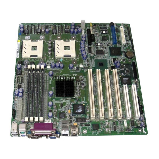
Page 11: Server Board Connector And Component Locations
Server Board Connector and Component Locations OM15026 A Primary Processor (CPU1) System Fan 3 System Fan 1 B Secondary Processor (CPU2) Front Panel Connector System Fan 2 C CPU Power Jumper Block CC ID LED D System Fan 6 Battery DD NIC 1 (10/100) E System Fan 5 LVD SCSI Connector... -
Page 12: Back Panel Connectors
An HI 1.5 bus that provides an interface to the ICH3-S (South Bridge) Other features provided by the MCH include the following: Full support of registered ECC on the memory bus Full support of Intel® x4 Single Device Data Correction on the memory interface with x4 DIMMs Twelve deep in-order queue... - Page 13 P64H2 I/O Hub The primary role of the P64H2 is to provide an integrated I/O bridge to the 64-bit PCI-X segments. This subsystem supports two independent 64-bit PCI-X segments, each with two 64-bit/100MHz PCI-X slots. The Adaptec AIC-7901 embedded controller is enabled via one of the PCI-X segments of the P64H2.
-
Page 14: Processor(S)
® The Intel Server Board SE7501BR2 accommodates one or two Intel Xeon processors with 512KB L2 Cache via two SKT604 604-pin zero-insertion force (ZIF) sockets. The processors interface with the system bus at 533 MHz, backwards compatible with 400 MHz. When only one processor is installed, it should be in the socket labeled CPU1 and the other socket must be empty. -
Page 15: Memory
Memory ® The Intel Server Board SE7501BR2 contains four 184-pin DIMM sockets and provides support for up to 8 GB of DDR266 memory. The memory subsystem provides dual memory bus architecture; the memory on the board is partitioned into two banks of DDR DIMMs. DIMMs must be installed in pairs, providing a 144-bit wide data path via two separate memory buses. - Page 16 Plug-and-Play ready Parity enabled NOTE If you install a slower card into one of the PCI-X 64/100 connectors, the bus speed for both connectors will be lowered to the speed of the slowest adapter. Intel Server Board SE7501BR2 Product Guide...
-
Page 17: Video Controller
The 32-bit / 33 MHz PCI segment includes the following embedded devices and connectors: Two 5 V keyed full-length, full height PCI expansion slots (PCI Slots 5 and 6) Integrated Intel 10/100 Fast Ethernet Controller (Intel 82550PM) Integrated Intel Gigabit Ethernet Controller (Intel 82540EM) -
Page 18: Network Interface Controllers (Nics)
Intel 82550PM Fast Ethernet Controller (NIC1) , and one 10/100/1000Base-TX network connection, based on Intel 82540EM Gigabit Ethernet Controller (NIC2). Facing the rear of the system, the gigabit controller is on the left, next to the video connector. You can disable the embedded NICs in BIOS Setup Utility. When disabled, the controller(s) are not visible to the operating system. -
Page 19: Table 3. 10/100 Megabit Leds (Nic1)
NIC Connector and Status LEDs ® The Intel Server Board SE7501BR2 supports two RJ45 connectors, one for the 10/100-Megabit Fast Ethernet controller (NIC1), and the other for the Gigabit Ethernet controller (NIC2). NIC1 drives two LEDs on its RJ45 connector. These LEDs indicate link/activity on the LAN and the speed of operation. -
Page 20: Acpi
This provides an option for users who want to use standard, but non-secure, Wake on LAN capability for operations such as after-hours maintenance. Server management features provide a secure system power-up, plus the ability to provide BIOS boot option. Intel Server Board SE7501BR2 Product Guide... -
Page 21: System Management
Software and Utilities chapter, beginning on page 77. Baseboard Management Controller Intel server boards incorporate a baseboard management controller (BMC), which is a dedicated microcontroller for system management activities. The BMC performs the following functions: Monitors system components and sensors, including processors, memory, fans, power supplies, temperature sensors, and chassis intrusion sensors. -
Page 22: Field Replaceable Units And Sensor Data Records
Memory error POST error Processor fault resilient booting (FRB) failure Fatal nonmaskable interrupt (NMI) from a source other than the front panel switch Watchdog timer reset, power down, or power cycle System restart (reboot) Intel Server Board SE7501BR2 Product Guide... -
Page 23: Emergency Management Port
The BMC controls the port and interfaces with remote access software, such as the Direct Platform Control or the Client System Setup Utility applications in Intel Server Management. You can configure the EMP by using the Server Configuration Wizard or the System Setup Utility. -
Page 24: Intel ® Server Management
® Server Management Intel Server Management (ISM) version 5.5 is a system management package that is included on the ISM CD. ISM applications interact with the integrated hardware system management features of the server to allow you to monitor and manage a server. Version 5.5 provides integrated in-band (operating system up) and out-of-band (operating system down) remote management, event alerting and logging, including e-mail notification, and proactive fault management. -
Page 25: Security
Security The SE7501BR2 BIOS provides a number of security features. This section describes the security features and their operation. Table 5. Security Operation Summary Entry Method/ Entry Mode Event Criteria Behavior Exit Criteria After Exit Secure Keyboard User On-board video goes User or Video is Mode... -
Page 26: Secure Mode
You cannot turn off system power or reset the server from the front panel switches. Secure mode has no effect on functions enabled via the Server Manager Module or power control via the real time clock. Intel Server Board SE7501BR2 Product Guide... -
Page 27: Password Protection
Password Protection The BIOS uses passwords to prevent unauthorized tampering with the system. Entering the user password permits the modification of the time, date, language, user password, and password on boot setup fields. When a user password is configured, the server can be booted into secure mode. -
Page 28: Intrusion Switch Monitoring
Intrusion Switch Monitoring To help prevent unauthorized entry or use of the server, the Intel Server Management software monitors the chassis intrusion switch if one is installed in the chassis. Opening an access cover will transmit an alarm signal to the server board, where BMC firmware and server management software process the signal. -
Page 29: Server Board Installations And Upgrades
To ensure EMC compliance with your local regional rules and regulations, the final configuration of your end system product may require additional EMC compliance testing. For more information please contact your local Intel Representative. See “Regulatory and Integration Information” on page 121 for product Safety and EMC regulatory compliance information. -
Page 30: Safety And Regulatory Compliance
(or higher) and operating at the same (or higher) speed as the microprocessor used on this server board. Server board diagram label provided: Place the label inside the chassis in an easy-to-see location, preferably oriented similarly to the server board. Intel Server Board SE7501BR2 Product Guide... -
Page 31: Minimum Hardware Requirements
To avoid integration difficulties and possible board damage, your system must meet the following minimum requirements. For a list of qualified memory and chassis components see: http://support.intel.com/support/motherboards/server/SE7501BR2 Processor Minimum of one Intel Xeon processor with 512K cache support. For a complete list of supported processors, see: http://support.intel.com/support/motherboards/server/SE7501BR2 Memory Minimum of two 128 MB ECC, DDR266 compliant registered DIMMs on 184-pin gold DIMMs. -
Page 32: Installation Procedures
Attaching the Gasket to the I/O Shield 1. Remove the backing strip from the gasket. 2. Press the gasket onto the inside face of the I/O shield as shown. OM14074 Figure 3. Attaching the Gasket to the I/O Shield Intel Server Board SE7501BR2 Product Guide... -
Page 33: Figure 4. Attaching The Label To The I/O Shield
Attaching the Label to the I/O Shield 1. Remove the backing from the label included with your server board. 2. Press the label onto the outside face of the I/O shield. Outside face of I/O shield OM14360 Figure 4. Attaching the Label to the I/O Shield Installing the I/O Shield The shield fits the rectangular opening in the back of a chassis. -
Page 34: Installing Chassis Standoffs
NOTE The Intel SC5200 chassis comes with positions 1, 4, 5, 6, 18, 20, 23, and 26 preinstalled. Install standoffs in the remaining positions (16, 19, and the eight marked P). Install standoffs in the eight positions marked P, regardless of whether one or two processors will be installed. -
Page 35: Installing The Rubber Bumper
Installing the Rubber Bumper 1. Measure and mark the bumper placement location in your chassis by placing your ruler against the standoffs as shown below. 2. Remove the backing from the bumper and press it firmly into position in the chassis. 3"... -
Page 36: Installing The Server Board
Using the screws that came with your chassis, mount the board to the chassis. OM14836 Figure 8. Attaching the Server Board NOTE If a single processor is to be used, insert the screws provided into the four standoffs that border the empty processor socket (CPU2). Intel Server Board SE7501BR2 Product Guide... -
Page 37: Making Connections To The Server Board
Making Connections to the Server Board OM14422 Auxiliary Power G. Front Panel Main Power H. Chassis Intrusion C. CPU1 Fan ATA 100 IDE D. CPU2 Fan Floppy Disk Drive Connector Processor Power System Fans 1, 2 (reading from top to bottom) System Fans 6, 5, 4, 3 (reading from top to bottom) Figure 9. -
Page 38: Cable Routing
SCSI cables that connect to devices in the lower device bays should be routed around the fan housing and ducts as shown below. Floppy Drive Cable Route the floppy drive cable as shown. Route cables here OM14641 Figure 10. Routing the SCSI and Floppy Drive Cable Intel Server Board SE7501BR2 Product Guide... -
Page 39: Installing Or Replacing Processor(S)
Make sure your server can handle a newer, faster processor (thermal and power considerations). For exact information about processor interchangeability, contact your customer service representative or visit the Intel Customer Support website: http://support.intel.com/support/motherboards/server/SE7501BR2... -
Page 40: Figure 11. Opening Socket Lever And Attaching Processor
SC5200 chassis or in a reference chassis. If you are installing the Server Board SE7501BR2 in the Intel® Server Chassis SC5200 Hot Swap Redundant Power, disregard this section and instead follow the instructions provided in the section titled, “Installing the Processor in the SC5200 Hot Swap Redundant Power Chassis”... -
Page 41: Figure 12. Attaching Retention Mechanism
6. Install the PWT retention mechanism over the top of the processor with the screws provided, as shown in Figure 12. OM15037 Figure 12. Attaching Retention Mechanism 7. Apply thermal grease to the top of the processor as shown in Figure 13. OM15040 Figure 13. -
Page 42: Figure 14. Attaching The Heat Sink And Retention Clip
11. Press downward on the ends of the retention clips to lock them into place over the plastic tabs (Figure 14, 3 and 4). NOTE Make sure the center tab engages in the heat sink base. OM15039A Figure 14. Attaching the Heat Sink and Retention Clip Intel Server Board SE7501BR2 Product Guide... -
Page 43: Figure 15. Attaching The Wind Tunnel Fan
12. Attach the fan between the two large plastic tabs at each side of the fan assembly component of the PWT (Figure 15, B). To ensure that the airflow direction is correct, insert the fan so that the label shows through the assembled unit (Figure 15, A). OM15041 Figure 15. -
Page 44: Figure 16. Attaching The Heat Sink Fan To The Top Of The Pwt
(Figure 16, 2) and insert them into the corresponding slots (Figure 16, 3). Rotate the fan assembly downward to engage the clips at the bottom (Figure 16, 4). OM15044 Figure 16. Attaching the Heat Sink Fan to the Top of the PWT Intel Server Board SE7501BR2 Product Guide... -
Page 45: Figure 17. Attaching The Top Assembly To The Retention Mechanism
14. Attach the fan assembly to the retention mechanism. Pull the tabs at the sides of the retention mechanism apart slightly. See Figure 17, 1. Lower the fan assembly into the retention mechanism. The tabs on the fan assembly (Figure 17, 3) will fit into the slots of the retention mechanism (Figure 17, 1). -
Page 46: Figure 18. Processor And Wind Tunnel Installed
CPU2 (Figure 18, B) indicate that this processor assembly is only required when configuring the server with two processors. The direction of the airflow is indicated by the arrow at (Figure 18, C). OM15038 Figure 18. Processor and Wind Tunnel Installed Intel Server Board SE7501BR2 Product Guide... -
Page 47: Figure 19. Installing The Processor Retention Brackets
Installing the Processor in the SC5200 Hot Swap Redundant Power Chassis NOTE Use these instructions if you are installing a processor in the Intel® Chassis SC5200 HSRP. When using this chassis, do not install the Processor Wind Tunnel. When installing the processor in any chassis other than the HSRP, disregard this section and follow the instructions in the section titled “Installing the Processor and the Processor Wind Tunnel in the SC5200 Chassis or in a Reference... -
Page 48: Figure 20. Raising The Locking Bar
4. Aligning the pins of the processor with the socket, insert the processor into the socket. NOTE Make sure the alignment triangle mark and the alignment triangle cutout align correctly. OM14133 Figure 21. Installing Processors Intel Server Board SE7501BR2 Product Guide... -
Page 49: Figure 22. Lower Locking Bar
5. Lower the locking bar completely. OM14135 Figure 22. Lower Locking Bar 6. Apply thermal grease to the top of the processor as shown. OM14366 Figure 23. Applying Thermal Grease Server Board Installation and Upgrades... -
Page 50: Figure 24. Installing The Heat Sink
7. Position the heat sink above the processor 8. Aligning the raised metal surfaces, place the heat sink on top of the processor. OM14134 Figure 24. Installing the Heat Sink Intel Server Board SE7501BR2 Product Guide... -
Page 51: Figure 25. Installing The Heat Sink Clip
9. Place the heat sink clip (1) so the tab on the clip engages the slot on the heat sink (A). 10. Press one end of the clip down (2). 11. Press the other end of the clip down (3). OM14140 Figure 25. -
Page 52: Installing Memory
DIMMs between banks, DIMMs must be identical within the banks. For a list of tested memory, see: http://support.intel.com/support/motherboards/server/SE7501BR2 DIMM 1A DIMM 1B DIMM 2A DIMM 2B OM14665 Figure 26. Installing Memory Intel Server Board SE7501BR2 Product Guide... -
Page 53: Finishing Up
Finishing Up WARNING An electrical shock hazard exists if the chassis cover is not replaced before connecting the chassis to the main power. 1. Install the chassis cover according to the instructions for your chassis. 2. See your chassis documentation to complete rack or pedestal installation. 3. -
Page 54: Replacing The Back Up Battery
CMOS RAM in the RTC (for example, the date and time) may be wrong. If you are using Intel Server Management you can set it to provide a warning prior to the battery failing. Contact your customer service representative or dealer for a list of approved devices. -
Page 55: Figure 28. Replacing The Backup Battery
1. Observe the safety and ESD precautions at the beginning of this chapter. 2. Open the chassis. 3. Insert the tip of a small flat bladed screwdriver, or equivalent, under the tab in the plastic retainer. Gently push down on the screwdriver to lift the battery. 4. - Page 56 Intel Server Board SE7501BR2 Product Guide...
-
Page 57: Post And The Bios Setup Utility
3 POST and the BIOS Setup Utility This chapter describes the Power-On Self-Test (POST) and the BIOS Setup utility. Power-On Self-Test (POST) Each time you turn on the system, the BIOS begins executing the Power-On Self-Test (POST), which is stored in flash memory. POST discovers, configures, and tests the processors, memory, keyboard, and most installed peripheral devices. -
Page 58: Bios Setup
In a third condition, when CMOS/NVRAM has been corrupted, you will see other messages but not the <F2> prompt: Warning: CMOS checksum invalid Warning: CMOS time and date not set In this condition, the BIOS will load default values for CMOS and attempt to boot. Intel Server Board SE7501BR2 Product Guide... -
Page 59: Setup Menus
Setup Menus Each Setup menu page contains a number of features. Except those used for information purposes, each feature is associated with a value field that contains user-selectable parameters. Parameters may be changed depending upon the security option chosen. If a value is not changeable due to insufficient security privileges (or other reasons), the feature’s value field becomes inaccessible. -
Page 60: Menu Selection Bar
Provides time to allow drives that spin-up slower to 3 seconds become ready. 6 seconds 9 seconds 12 seconds 15 seconds 21 seconds 30 seconds Primary IDE Master <Enter> Displays the IDE device selection. Enters submenu. continued Intel Server Board SE7501BR2 Product Guide... -
Page 61: Table 10. Primary/Secondary, Master/Slave Submenu
Table 9. Main Menu (continued) Primary IDE Slave <Enter> Displays IDE device selection. Enters submenu. Secondary IDE Master <Enter> Displays IDE device selection. Enters submenu. Secondary IDE Slave <Enter> Displays IDE device selection. Enters submenu. Processor Settings <Enter> Enters submenu. Language English (US) Selects the language displayed by the BIOS. -
Page 62: Advanced Menu
The system automatically resets this field to No during the next boot. Numlock Selects the state of the Numlock key at system power-on. Enabled Sleep Button When disabled, the sleep button will be disabled. Disabled Intel Server Board SE7501BR2 Product Guide... -
Page 63: Table 13. Pci Configuration Submenu
Table 13. PCI Configuration Submenu Feature Choices Description USB Function <Enter> Enters submenu. On-board NIC 1 <Enter> Enters submenu. (10/100 MB) On-board NIC 2 (1.0 GB) <Enter> Enters submenu. On-board SCSI <Enter> Enters submenu. On-board Video <Enter> Enters submenu. PCI Slot 1 ROM Enabled Enables or disables the option ROM scan of the device in Disabled... -
Page 64: Table 15. Peripheral Configuration Submenu
If disabled, legacy USB support is turned off at the end of Keyboard only BIOS POST. Auto Keyboard and Mouse Front Panel USB Enabled If disabled, the front panel USB ports are inactive. Disabled Intel Server Board SE7501BR2 Product Guide... -
Page 65: Table 16. Memory Configuration Submenu
Table 16. Memory Configuration Submenu Choices or Feature Display Only Description Extended Memory 1 MB Selects the size of step to use during the extended RAM tests. Test 1 KB When disabled is selected, extended memory tests are not run. Every Location The Every Location selection will increase the boot time. -
Page 66: Security Menu
This option is only available if a User Password is configured. None Fixed Disk Boot When Write Protect is enabled, the boot sector of the hard drive is Sector Write Protect protected. This prevents viruses from corrupting the drive. continued Intel Server Board SE7501BR2 Product Guide... -
Page 67: Server Menu
Table 18. Security Menu (continued) Feature Choices Description Secure Mode Timer 1 minute This option sets the number of minutes of PS/2 keyboard or mouse 2 minutes inactivity that are allowed before Secure Mode is activated. This 5 minutes option is only available if a User Password is configured. 10 minutes 20 minutes 60 minutes... -
Page 68: Table 20. System Management Submenu
Information only Chassis Part Number Information only Chassis Serial Number Information only BIOS Revision Information only displaying the revision of the BIOS installed BMC Device ID Information only BMC Firmware Revision Information only continued Intel Server Board SE7501BR2 Product Guide... -
Page 69: Table 21. Console Redirection Submenu
Table 20. System Management Submenu (continued) Boot Priority Device Description BMC Device Revision Information only PIA Revision Information only SDR Revision Information only Primary HSBP Revision Information only, displaying the revision of the Hot-swap backplane. This information is not available if the HSBP is not detected. -
Page 70: Table 22. Event Log Configuration Submenu
PXE 15 minutes specification. 20 minutes This option is not available if the Boot Monitoring option on the Disabled Server Menu is not set to Disabled. Intel Server Board SE7501BR2 Product Guide... -
Page 71: Boot Menu
Boot Menu You can make the following selections from the Boot Menu. Table 24. Boot Menu Boot Priority Device Description Boot Device Priority <Enter> Enters submenu Hard Disk Drives <Enter> Enters submenu Removable Devices <Enter> Enters submenu ATAPI CD-ROM Drives <Enter>... -
Page 72: Exit Menu
Load Custom Defaults Load values from previously saved custom defaults. This option is not available if no custom defaults are detected. Save Custom Defaults Stores custom defaults in NVRAM. Discard Changes Read previous values from NVRAM. Intel Server Board SE7501BR2 Product Guide... -
Page 73: Upgrading The Bios
The BIOS can be upgraded in-band (operating system up) or out-of-band (operating system down). The following instructions reflect the out-of-band upgrade steps. For in-band upgrade instructions, refer to the Intel® Server Management Installation and User’s Guide. Preparing for the Upgrade Before you upgrade the BIOS, prepare for the upgrade by recording the current BIOS settings and obtain the upgrade utility. -
Page 74: Performing The Bios Upgrade
Setup, check your settings, save your settings, and exit Setup. It is unlikely that anything will interrupt the BIOS upgrade; however, if an interruption occurs, the BIOS could be damaged. See “Recovering the BIOS” on page 112 for instructions. Intel Server Board SE7501BR2 Product Guide... -
Page 75: Changing The Bios Language
You can use the BIOS upgrade utility to change the language that the BIOS uses for messages and for the Setup program. Use a bootable diskette containing the Intel flash utility and language files. 1. Boot the computer with the bootable diskette in drive A. The BIOS upgrade utility screen appears. -
Page 77: Configuration Software And Utilities
4 Configuration Software and Utilities System Software Update Sequence When you update the system software, you should do it in the following order. 1. Update firmware (BMC & HSC) 2. Update FRU/SDR 3. Unplug system for 30 seconds 4. Update BIOS 5. -
Page 78: Server Configuration Wizard
In addition, you can select only one of the following at a time: Load SDRs only onto this server Load FRUs and SDRs onto this server If you select multiple options, the Server Configuration Wizard will run each option to completion. Intel Server Board SE7501BR2 Product Guide... -
Page 79: Direct Platform Control (Dpc) Console
RS-232 serial connection to the server Serial B port over a modem or a direct serial cable. The Direct Platform Control Console provides the ability for remote management of Intel servers via modem or LAN with a capability to run DOS-based programs. -
Page 80: Dpc Console Modes Of Operation
Running the DPC Console For more information about setting up and running the DPC Console, see the ISM Installation User’s Guide. This document is in the ISM\DOCS\[language] directory on the ISM CD accompanying the SE7501BR2 server board. Intel Server Board SE7501BR2 Product Guide... -
Page 81: Using The System Setup Utility
Using the System Setup Utility The System Setup Utility (SSU) is located on the System Resource CD-ROM that is shipped with the server. Run the System Setup Utility to: Set boot device priority Set passwords and security options View system events View FRU information View sensor data records Update system firmware and BIOS... -
Page 82: Running The Ssu
The tasks achieve complete control by keeping the task as the center of operation until you close the task window. The SSU has a build-in help system, which you access by clicking a Help button or choosing the Help menu. Intel Server Board SE7501BR2 Product Guide... -
Page 83: Setting Boot Device Priority
Customizing the SSU Interface The SSU lets you customize your interface using the Preferences section of the main window. The AF sets these preferences and saves them in the AF.INI file so that they take effect the next time you start the SSU. There are four user customizable settings: Color: lets you change the default colors associated with different items on the screen using predefined color combinations. - Page 84 Disable allows the power and reset buttons to function normally when the server is in secure mode. 3. Click Save to save the settings and return to the Security window. Intel Server Board SE7501BR2 Product Guide...
-
Page 85: Viewing The System Event Log
Viewing the System Event Log To view the System Event Log (SEL): 1. From the SSU Main window, choose SEL Manager. When you start the SEL Manager, it automatically loads the current list of events from non-volatile memory. 2. Use the <F4> and <F5> keys to scroll the window contents to the left and right to view all of the columns. -
Page 86: Viewing Sensor Data Records
Using the SSU, you can update the BIOS, update the firmware, and verify the firmware. Procedures for each are given below. You can also update the BIOS and firmware without using the SSU. You can download the updates from the Intel support website: http://support.intel.com/support/motherboards/server... -
Page 87: Managing The Server Remotely
Updating the Firmware To update the system firmware: 1. Download the update from the Intel support website. 2. From the SSU Main window, choose System Update. (System Update is available only in Expert mode.) When you start System Update, it automatically displays the current revision information for the system firmware and BIOS. - Page 88 Verify New Password box. Passwords can be from 1 to 16 characters long, using any ASCII character in the range [32-126]. To clear the passwords, leave both boxes blank. (You can also clear the password by choose the menu Options > Clear LAN Password.) Intel Server Board SE7501BR2 Product Guide...
-
Page 89: How To Set Up Remote Modem Or Serial Access
4. From the LAN Access Mode list, select the remote access mode: Always Available: a remote system can initiate a LAN connection regardless of the state or health of the server. Restricted: a remote system can initiate a LAN connection, but cannot perform control operations such as power down, reset, or front panel NMI. - Page 90 Direct Connect: the Serial B port on the server is connected by a serial cable to the remote system. Modem Connect: the Serial B port on the server is connected to a modem. 9. Click Save to save the changes. 10. Click Close to return to the PEM window. Intel Server Board SE7501BR2 Product Guide...
-
Page 91: How To Set Up Paging Alerts
How to Set Up Paging Alerts To set up the server so it pages you in the event of an alert, you can use either the Server Configuration Wizard or the System Setup Utility. To use the Server Configuration Wizard to configure the server to send alerts as telephone pages: 1. - Page 92 15. To send a test page to verify that you have correctly configured PEP, from the Options menu, choose Send Alert. 16. Click Save to save the configuration. 17. Click Close to return to the Platform Event Manager window. Intel Server Board SE7501BR2 Product Guide...
-
Page 93: How Set Up Lan Alerts
To set up the server to send alerts over the LAN you can use either the SSU or the SCW. For more information about LAN alerts, see the documentation for Intel Server Management software. To use the Server Configuration Wizard to configure the server to send alerts over the LAN: 1. - Page 94 10. Click Save to save the changes. 11. Click Close to return to the BMC LAN Configuration window. 12. Click Save to save the changes. 13. Click Close to return to the PEM window. Intel Server Board SE7501BR2 Product Guide...
-
Page 95: Firmware Update Utility Description
7. The program will load the file and then ask if it should upload boot code. Press “N” to continue unless otherwise directed by the release notes or an Intel support professional. 8. The program next asks if it should upload operational code. Press “Y” to continue. The process of uploading operational code takes a few minutes. -
Page 96: How To Use The Fru/Sdr Load Utility
A .cfg file describing the system configuration An .sdr file describing the sensors in the system The command line format to do this is: FRU/SDR [-?] [-h] [-d {fru, sdr}] [-cfg filename.cfg] [-fru filename.fru] Intel Server Board SE7501BR2 Product Guide... -
Page 97: Table 32. Command Line Format
Table 32. Command Line Format Command Description -? or -h Displays usage information. -d {fru, sdr} Displays requested area only. -cfg filename.cfg Uses custom CFG file. Pause between blocks of data. Parsing the Command Line The FRU/SDR load utility allows only one command line function at a time. A command line function can consist of two parameters. -
Page 98: Setting A System Asset Tag
If you selected utility / device driver, you will see a list of drivers and utilities from which to select. Select the appropriate operating system(s), utilities, and device driver(s) and Continue. Intel Server Board SE7501BR2 Product Guide... -
Page 99: Installing A Service Partition (Optional)
The service partition includes utilities, and other software that can be run locally or remotely to assist in server management. The service partition uses approximately 40 MB of hard disk space. The service partition can be installed either with the Server Configuration Wizard or with the Intel Server Management CD. -
Page 100: Saving And Restoring The System Configuration
To save the system configuration from the Server Configuration Wizard: 1. Follow the configuration prompts until you see “Save Server Configuration.” 2. Select the “Save Server Configuration” checkbox and click Continue. 3. Specify a filename and location as prompted. Intel Server Board SE7501BR2 Product Guide... - Page 101 Loading a Saved Configuration To load a previously saved system configuration from a file using the System Setup Utility: 1. From the SSU Main window, choose Config Save/Restore. (Configuration Save/Restore is available only in Expert mode.) 2. Click Restore from File and specify a filename and location. NOTE You can load only a configuration that had been previously saved with the SSU.
-
Page 102: Using The Intel Server Management And Intel Smart Tool (Optional)
Remote access is provided through either a modem or network connection. To get started with Intel Server Management, install the Service Partition first. See “Installing a Service Partition (Optional)”, page 99. After the service partition is installed, install operating system, and then Intel Server Management and the Intel SmaRT Tool. -
Page 103: Installing Intel Server Management
Installing Intel Server Management You can install Intel Server Management on a local server or on a remote workstation that is used to manage a LAN/WAN. 1. Insert the Intel Server Management CD into the system’s CD-ROM. 2. Click Install Server Management. - Page 104 Intel Server Board SE7501BR2 Product Guide...
-
Page 105: Solving Problems
NEMA 5-15R outlet for 100-120 V or a NEMA 6-15R outlet for 200-240 V ? ! Are all integrated components from the tested components lists? Check the tested memory, and chassis lists, as well as the supported hardware and operating system list on the Intel Customer Support website. -
Page 106: Running New Application Software
If you are experiencing any of the above symptoms that might indicate voltage spikes on the power line, you may want to install a surge suppressor between the power outlet and the system power cord. Intel Server Board SE7501BR2 Product Guide... -
Page 107: More Problem Solving Procedures
More Problem Solving Procedures This section provides a more detailed approach to identifying a problem and locating its source. Preparing the System for Diagnostic Testing CAUTION Turn off devices before disconnecting cables: Before disconnecting any peripheral cables from the system, turn off the system and any external peripheral devices. -
Page 108: Specific Problems And Corrective Actions
! Are the brightness and contrast controls on the video monitor properly adjusted? ! Are the video monitor switch settings correct? ! Is the video monitor signal cable properly installed? ! Is the onboard video controller enabled? Intel Server Board SE7501BR2 Product Guide... -
Page 109: Characters Are Distorted Or Incorrect
If you are using an add-in video controller board, do the following: 1. Verify that the video controller board is fully seated in the server board connector. 2. Reboot the system for changes to take effect. 3. If there are still no characters on the screen after you reboot the system and POST emits a beep code, write down the beep code you hear. -
Page 110: Diskette Drive Activity Light Does Not Light
! If you are directly connecting two servers (no hub), you will need a crossover cable (see your hub documentation for more information on crossover cables). ! Check the network controller LEDs that are visible through an opening at the system back panel. Intel Server Board SE7501BR2 Product Guide... -
Page 111: Problems With Network
Problems with Network Diagnostics pass, but the connection fails. ! Make sure the network cable is securely attached. ! Make sure you specify the correct frame type in your NET.CFG file. The Front Panel Activity LED doesn’t light. The network activity LED is not connected to the SE7501BR2 server board front panel. The controller stopped working when an add-in adapter was installed. -
Page 112: Recovering The Bios
4. Move the BIOS recovery jumper to the recovery state, covering pins 10 and 11 with the jumper. In the figure below, the recovery jumper is labeled “Recovery Boot.” Figure 29. BIOS Recovery Jumper Intel Server Board SE7501BR2 Product Guide... - Page 113 5. Insert the bootable BIOS recovery diskette that contains the BIOS update files. 6. Replace the AC power cord and turn on the system power. The recovery BIOS boots from the recovery diskette and emits one beep when it passes control to DOS.
-
Page 114: Clearing The Password With The Password Jumper
4. Reconnect the AC power, power up the system. 5. Power down the system and disconnect the AC power. 6. Return the Password Clear jumper to its original position, covering pins 5 and 6. 7. Close the server chassis. Intel Server Board SE7501BR2 Product Guide... -
Page 115: Clearing Cmos With The Cmos Jumper
Clearing CMOS with the CMOS Jumper If you are not able to access the BIOS setup screens, the CMOS Clear jumper will need to be used to reset the configuration RAM. The CMOS Clear jumper is located on jumper block J1H1 on the SE7501BR2 board. - Page 116 Intel Server Board SE7501BR2 Product Guide...
-
Page 117: Getting Help
Telephone All calls are billed US $25.00 per incident, levied in local currency at the applicable credit card exchange rate plus applicable taxes. (Intel reserves the right to change the pricing for telephone support at any time without notice.) In U.S. and Canada... - Page 118 Intel Server Board SE7501BR2 Product Guide...
-
Page 119: Technical Reference
7 Technical Reference Configuration Jumpers J106 OM14670 Figure 32. Configuration Jumper Location Table 33. Configuration Jumper (J1H1) Jumper Name Pins What happens at system reset CMOS normal These pins are for normal operation. operation CMOS clear If these pins are jumpered, the CMOS settings will be cleared on the next reset. -
Page 120: Front Panel Header
7 & 9 LED show hard disk drive activity 1 & 5 LED shows power on 22 & 24 LED shows network interface controller activity 12 & 14 LED shows network interface controller activity Intel Server Board SE7501BR2 Product Guide... -
Page 121: Regulatory And Integration Information
® electromagnetic compatibility (EMC) regulations when installed a compatible Intel host system. For information on compatible host system(s) refer to Intel’s Server Builder website or contact your local Intel representative. FCC (Class A Verification) – Radiated & Conducted Emissions (USA) ICES-003 (Class A) –... -
Page 122: Product Regulatory Compliance Markings
This product is marked with the following Product Certification Markings: Table 35. Product Certification Markings UL Recognition Mark CE Mark Russian GOST Mark Australian C-Tick Mark BSMI DOC Marking BSMI EMC Warning RRL MIC Mark Intel Server Board SE7501BR2 Product Guide... -
Page 123: Electromagnetic Compatibility Notices
(1) this device may not cause harmful interference, and (2) this device must accept any interference received, including interference that may cause undesired operation. For questions related to the EMC performance of this product, contact: Intel Corporation 5200 N.E. Elam Young Parkway Hillsboro, OR 97124... -
Page 124: Industry Canada (Ices-003)
MIC logo to illustrate compliance. The English translation for the above is as follows: 1. Type of Equipment (Model Name): SE7501BR2 2. Certification No.: Contact Intel Representative 3. Name of Certification Recipient: Intel 4. Date of Manufacturer: Marked on Product 5. -
Page 125: Index
Index BIOS upgrade file, 74 BMC, 22. see Baseboard Management Controller ACPI, see Advanced Configuration and Power board, how to install, 36 Interface boot monitoring, configuring, 68 Adaptec AIC-7901, 9, 13, 16 boot priority, 71, 81 Administrator password, 84 one-time change, 57 Advanced Configuration and Power Interface, Boot sequence, selecting, 83 booting... - Page 126 DPC over LAN, 80 FRU, see Field Replaceable Unit Drive type, select, 61 FRU/SDR Load Utility, 22, 77, 79, 95 how to create diskettes, 98 FRU/SDR records, how to load, 96 E7501 chipset, 9 ECC, 15 Intel Server Board SE7501BR2 Product Guide...
- Page 127 Intel 82550, 9, 10, 17, 18 mouse controller, 13 features, 18 mouse port, 10 ® Intel E7501 chipset, 9 M-ROMB, 17 ® Intel SMaRT Tool, 102 Multi-Sector Transfer Interrupt controller, 13 select, 61 ® ISM, see Intel Server Management Index...
- Page 128 107 expansion slots, 9 processor speed, 17 adding second processor, 39 PCI Bus Master Interface, 18 apply thermal grease, 41, 49 PCI bus segments, 15 heat sink, 42, 50 PCI Riser, 16 Intel Server Board SE7501BR2 Product Guide...
- Page 129 installing, 39 effect of, 26 replacing, 51 floppy write protection, 28 retention clips, 42, 51 hot key, 67 test, 62 immediate activation, 26 power switch, 67 processor airflow, 14 timer, 67 processor speed, 14 video blanking, 67 processor wind tunnel, 14, 40 Secure mode, 26 alignment, 45 Secure mode boot, 84...
- Page 130 29 TFT displays, 17 dispose of lithium battery safely, 54 Transfer Mode, 61 ESD can damage product, 30 hazardous electrical conditions, 29 WOL, see Wake on LAN18 Ultra320, 9 Ultra DMA Mode, configuring, 61 Intel Server Board SE7501BR2 Product Guide...