Vulcan-Hart K12ETT ML-136068 Service Manual
Electric counter top tilting kettles
Hide thumbs
Also See for K12ETT ML-136068:
- Installation & operation manual (12 pages) ,
- Specifications (2 pages) ,
- Service manual (28 pages)
Table of Contents
Advertisement
Quick Links
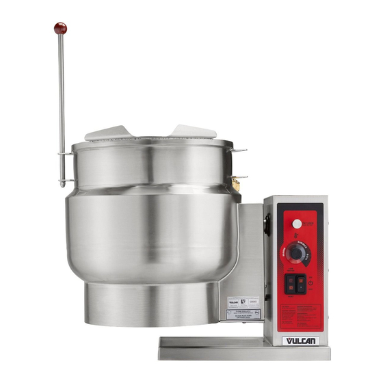
K12ETT ON STAND
This Manual is prepared for the use of trained Vulcan Service
Technicians and should not be used by those not properly qualified.
This manual is not intended to be all encompassing. If you have not
attended a Vulcan Service School for this product, you should read,
in its entirety,
determine if you have the necessary tools, instruments and skills
required to perform the procedure. Procedures for which you do not
have the necessary tools, instruments
performed by a trained Vulcan Service Technician.
Reproduction or other use of this Manual, without the express
written consent of Vulcan, is prohibited.
For additional information on Vulcan-Hart or to locate an authorized parts and
service provider in your area, visit our website at www.vulcanhart.com.
VULCAN-HART
A product of
ELECTRIC COUNTER TOP
the repair procedure you wish to perform
SERVICE MANUAL
TILTING KETTLES
K6ETT
ML-136067
K12ETT
ML-136068
K20ETT
ML-136069
to
and skills should be
LOUISVILLE, KY 40201-0696
F35496 (August 2009)
Advertisement
Table of Contents

Related Manuals for Vulcan-Hart K12ETT ML-136068


Summary of Contents for Vulcan-Hart K12ETT ML-136068
-
Page 1: Tilting Kettles
Vulcan Service Technician. Reproduction or other use of this Manual, without the express written consent of Vulcan, is prohibited. For additional information on Vulcan-Hart or to locate an authorized parts and service provider in your area, visit our website at www.vulcanhart.com. VULCAN-HART... -
Page 2: Table Of Contents
TROUBLESHOOTING ..............27 © VULCAN 2009... -
Page 3: General
ELECTRIC COUNTER TOP TILTING KETTLES - GENERAL GENERAL INTRODUCTION CONTROL PANEL General The procedures in this manual apply to all models unless otherwise specified. The pictures and illustrations are of a model K6ETT countertop tilting kettle unless otherwise noted. All information and specifications contained in this manual are based on the latest product information available at the time of printing. -
Page 4: Specifications
ELECTRIC COUNTER TOP TILTING KETTLES - GENERAL SPECIFICATIONS Reservoir Jacket Fluid • Water - Use only distilled water for partial re-filling of the jacket (purchase locally). • Dowfrost heat transfer fluid Part No. 558038 (5 gallon). Use during a complete re-fill of the jacket with new fluid. -
Page 5: Removal And Replacement Of Parts
ELECTRIC COUNTER TOP TILTING KETTLES - REMOVAL AND REPLACEMENT OF PARTS REMOVAL AND REPLACEMENT OF PARTS COVERS AND PANELS ELECTRICAL PANEL COMPONENTS - WATER LEVEL CONTROL, TRANSFORMER, CONTACTORS AND TEMPERATURE CONTROL Control Box Cover Remove CONTROL BOX COVER. Disconnect lead wires from component being replaced. -
Page 6: Bottom Components - Water Level Probe (Llco), Temperature Sensor And Pressure Switch
ELECTRIC COUNTER TOP TILTING KETTLES - REMOVAL AND REPLACEMENT OF PARTS BOTTOM COMPONENTS - POTENTIOMETER WATER LEVEL PROBE (LLCO), TEMPERATURE SENSOR AND PRESSURE SWITCH Remove CONTROL BOX COVER. Disconnect potentiometer wire from temperature control. Open pressure relief valve until reservoir jacket Pull temperature dial from potentiometer shaft is completely vented. -
Page 7: Heating Element
ELECTRIC COUNTER TOP TILTING KETTLES - REMOVAL AND REPLACEMENT OF PARTS Reverse procedure to install. Use a new heating HEATING ELEMENT element seal whenever installing heating element. Torque mounting bolts to 40 ft-lbs and tighten in an alternating pattern. Remove air from reservoir jacket as outlined under VENTING. -
Page 8: Kettle Assembly
ELECTRIC COUNTER TOP TILTING KETTLES - REMOVAL AND REPLACEMENT OF PARTS KETTLE ASSEMBLY Removal Place kettle in full upright position. Support kettle using 2x4 blocks of wood. Remove outer bearing from support shaft. Remove CONTROL BOX COVER. On K20ETT only. Disconnect thermocouple lead wires from Remove two bolts securing kettle tilt stop temperature control and the 4 pin wiring... - Page 9 ELECTRIC COUNTER TOP TILTING KETTLES - REMOVAL AND REPLACEMENT OF PARTS 11. If re-installing kettle assembly, proceed to Installation in this section. If installing a replacement kettle assembly, remove components as outlined below from old kettle assembly for re-use. Open pressure relief valve until reservoir jacket is completely vented.
- Page 10 ELECTRIC COUNTER TOP TILTING KETTLES - REMOVAL AND REPLACEMENT OF PARTS Square the kettle assembly to control box Slide pivot stop collar onto support shaft. housing. Maintain squareness during Operate tilt lock then slide collar against adjustments. inner bearing. Hold the collar in position and release tilt lock.
-
Page 11: Bearings
ELECTRIC COUNTER TOP TILTING KETTLES - REMOVAL AND REPLACEMENT OF PARTS NOTE: Allow cleaner to fully evaporate before BEARINGS applying primer. Spay primer on the threads and allow to dry for 60 seconds. Shake Loctite 242 bottle Remove KETTLE ASSEMBLY (procedure thoroughly to mix then apply several drops of the includes outer bearing removal). -
Page 12: Shaft Seal
ELECTRIC COUNTER TOP TILTING KETTLES - REMOVAL AND REPLACEMENT OF PARTS SHAFT SEAL All Models To access shaft seal between kettle and control box housing, remove KETTLE ASSEMBLY. Remove shaft seal from control box housing. Remove kettle support and bearing housing assembly from support shaft. -
Page 13: Pivot Stop Pin
ELECTRIC COUNTER TOP TILTING KETTLES - REMOVAL AND REPLACEMENT OF PARTS Reverse procedure to complete the installation and check for proper operation. K20ETT WITH SHAFT SEAL INSTALLED PIVOT STOP PIN Remove CONTROL BOX COVER. Remove retaining ring from pivot stop pin. Reverse procedure to install. -
Page 14: Service Procedures And Adjustments
ELECTRIC COUNTER TOP TILTING KETTLES - SERVICE PROCEDURES AND ADJUSTMENTS SERVICE PROCEDURES AND ADJUSTMENTS Verify heat light (amber) comes on and TEMPERATURE CONTROLLER heating element is energized. TEST If heat light does not remain on or flashes momentarily as temperature setting is slowly increased, verify condition of potentiometer as outlined under POTENTIOMETER TEST. -
Page 15: Potentiometer Test
ELECTRIC COUNTER TOP TILTING KETTLES - SERVICE PROCEDURES AND ADJUSTMENTS POTENTIOMETER TEST THERMOCOUPLE TEST Remove potentiometer from control panel as Access the temperature controller as outlined in outlined in REMOVAL AND REPLACEMENT REMOVAL AND REPLACEMENT OF PARTS. OF PARTS. Remove thermocouple lead wires from Turn potentiometer shaft fully counterclockwise temperature controller. -
Page 16: Heating Elements
ELECTRIC COUNTER TOP TILTING KETTLES - SERVICE PROCEDURES AND ADJUSTMENTS HEATING ELEMENTS Access heating element as outlined in REMOVAL AND REPLACEMENT OF PARTS. Measure voltage at heating element terminals and verify it against the data plate voltage. If voltage is incorrect, find the source of the problem. If voltage is correct, check current draw (amps) through the heating element lead wires. -
Page 17: Venting
ELECTRIC COUNTER TOP TILTING KETTLES - SERVICE PROCEDURES AND ADJUSTMENTS VENTING FILLING THE RESERVOIR JACKET NOTE: This procedure outlines venting the reservoir jacket to remove air for proper heat transfer to the NOTE: The reservoir water level must be maintained kettle contents. - Page 18 ELECTRIC COUNTER TOP TILTING KETTLES - SERVICE PROCEDURES AND ADJUSTMENTS Complete Draining and Refill NOTE: Appearance of fluid will no longer be clear after usage in kettle. Turn power switch off and set temperature dial to lowest setting. Open pressure relief valve until reservoir jacket is completely vented.
-
Page 19: Electrical Operation
ELECTRIC COUNTER TOP TILTING KETTLES - ELECTRICAL OPERATION ELECTRICAL OPERATION COMPONENT FUNCTION Water Level Control (WLC LLCO) ..Low water level control. Monitors condition of the WLC LLCO water level probe. Protects kettle from a low water condition in the reservoir jacket and removes power from heating circuit when kettle is tilted. -
Page 20: Component Location
ELECTRIC COUNTER TOP TILTING KETTLES - ELECTRICAL OPERATION COMPONENT LOCATION F35496 (August 2009) Page 20 of 28... - Page 21 ELECTRIC COUNTER TOP TILTING KETTLES - ELECTRICAL OPERATION Page 21 of 28 F35496 (August 2009)
-
Page 22: Water Level Control (Wlc Llco)
ELECTRIC COUNTER TOP TILTING KETTLES - ELECTRICAL OPERATION WATER LEVEL CONTROL (WLC LLCO) The water level control provides low level cut-off protection to shut off the heat source in case the fluid level in the kettle reservoir jacket drops below the WLC LLCO probe. A single low level cut-off probe (LLCO) is connected to the control. -
Page 23: Sequence Of Operation
ELECTRIC COUNTER TOP TILTING KETTLES - ELECTRICAL OPERATION SEQUENCE OF OPERATION Conditions. Kettle connected to correct voltage supply and is properly grounded. 120VAC potential across X2 and X1 on secondary of main transformer. Power switch and light (1LT) (amber) are off. Low water light (2LT) (red) is off. -
Page 24: Schematic Diagram
ELECTRIC COUNTER TOP TILTING KETTLES - ELECTRICAL OPERATION SCHEMATIC DIAGRAM F35496 (August 2009) Page 24 of 28... -
Page 25: Wiring Diagrams
ELECTRIC COUNTER TOP TILTING KETTLES - ELECTRICAL OPERATION WIRING DIAGRAMS Heating Element Wiring Page 25 of 28 F35496 (August 2009) - Page 26 ELECTRIC COUNTER TOP TILTING KETTLES - ELECTRICAL OPERATION F35496 (August 2009) Page 26 of 28...
-
Page 27: Troubleshooting
ELECTRIC COUNTER TOP TILTING KETTLES - TROUBLESHOOTING TROUBLESHOOTING SYMPTOM POSSIBLE CAUSES Kettle does not heat, power light is lit, heat 1. Limiting contactor (1CON) malfunction. light is lit, low water light is not lit. 2. Regulating contactor (2CON) malfunction. 3. Heating element malfunction. Kettle does not heat, power light is lit, low 1. - Page 28 ELECTRIC COUNTER TOP TILTING KETTLES F35496 (August 2009) Printed in U.S.A.