
Related Manuals for Brother HE-800B


Summary of Contents for Brother HE-800B
- Page 1 HE-800B INSTRUCTION MANUAL Please read this manual before using the machine. Please keep this manual within easy reach for quick reference. ELECTRONIC DIRECT DRIVE LOCKSTITCH BUTTON HOLER...
- Page 2 Follow the instructions from training personnel and instructors regarding safe and correct operation before operating the machine so that you will know how to use it correctly. HE-800B...
-
Page 3: Safety Instructions
This symbol ( ) indicates something that you must do. The picture inside the circle indicates the ・・・・・・ nature of the thing that must be done. (For example, the symbol at left means “you must make the ground connection”.) HE-800B... - Page 4 Be sure to connect the ground. If the ground Keep the oil out of the reach of children. connection is not secure, you run a high risk of receiving a serious electric shock, and problems with correct operation may also occur. HE-800B...
-
Page 5: Maintenance And Inspection
If the power switch needs to be left on when carrying Brother will not be held responsible for any accidents out some adjustment, be extremely careful to observe or problems resulting from modifications made to the all safety precautions. machine. HE-800B... - Page 6 Be careful to avoid injury from the moving cutter. Be sure to connect the ground. If the ground connection is not secure, you run a high risk of receiving a serious electric shock, and problems with correct operation may also occur. HE-800B...
- Page 7 4730M Oil tank (accessory) 4731M 4732M HE-800B...
-
Page 8: Table Of Contents
4-5-1. Lower thread tension......26 7-5. Changing the production counter setting ..59 4-5-2. Upper thread tension......27 7-6. Displaying the help screen......60 4-5-3. Thread take-up spring height ....28 4-5-4. Thread take-up spring tension .... 28 4-5-5. Adjusting arm thread guide ....28 HE-800B... - Page 9 11-29. Upper shaft does not rotate as far as 11-6. Uneven seams (4) …… the needle up stop position......96 Uneven sewing pitch at the sewing start... 82 11-30. Operation panel display freezes and 11-7. Uneven seams (5) …… operation is not possible......96 Poor rounding of seam......... 82 HE-800B...
-
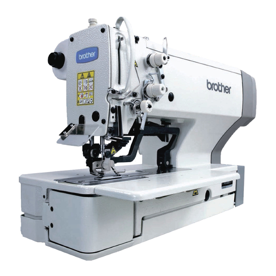
Page 10: Names Of Major Parts
(1) Power switch (2) Control box (3) Operation panel (4) Treadle (5) Stop switch (6) Cotton stand (7) Tension release lever (8) Pulley Safety devices (9) Eye guard (10) Thread take-up cover (11) Finger guard (12) Motor cover (13) Slide cover HE-800B... -
Page 11: Specifications
SD memory card (No guarantees of operation can be given for any media.) Single-phase 100V / 220V, 3-phase 220V / 380V / 400V Power supply (For single-phase 100 V and three-phase 380 V/400 V, the trans box is required.) HE-800B... -
Page 12: Standard Sewing Pattern List
2. SPECIFICATIONS 2-2. Standard sewing pattern list Rectangle Radial Round Straight bar tack Rear tack Front tack Radial-rectangle Round-rectangle Eyelet-rectangle Rectangle-radial Round-radial Eyelet-radial Rectangle-round Radial-round Eyelet-round Rectangle-taper tack Radial-taper tack Round-taper tack Eyelet-taper tack Rectangle-tack Radial-tack Round-tack Eyelet-tack HE-800B... -
Page 13: Installation
Check that the control box is at least 10 mm away from the leg. If the control box and the leg are too close together, ・ it may result in incorrect sewing machine operation. 4938M HE-800B... -
Page 14: Installing The Control Box
If this is not done, injury to feet or damage to the control box may result. Before installing the control box, check that the model plate (a) on the control box is “HX800B” to indicate that it is an HX-control box for HE-800B sewing machines. Remove the six screws (1), and then 4735M remove the control box cover (2). -
Page 15: Installing The Flange Nut
3. Install the bed base (1) with the three flat washers (5) and wood screws (6), and then install the two rubber caps (7). 4. Remove the four bolts (3). 5. Set the magnet (8) in the position shown in the illustration. 4069M HE-800B... -
Page 16: Installing The Machine Head
Tap the head rest (1) securely into the table hole. If the head rest (1) is not pushed in as far as it will go, the machine head will not be sufficiently stable when it is tilted back. 4740M HE-800B... -
Page 17: Installing The Operation Panel
NOTE: Check that the operation panel cord is not being clamped when screwing the operation panel into the table. The cord may become damaged if it is clamped. 4742M HE-800B... -
Page 18: Installing The Oil Stopper Plate
1. Pass the cord bundle (1) through the hole in the work table. 2. Pass the cord bundle (1) through the hole (2) into the control box. 3. Securely connect the connectors as indicated in the table below. (Refer to the next page.) 4745M HE-800B... - Page 19 P2 (SOL) – NOTE: Route the needle zigzag, feed and work clamp motor harnesses and the tension release solenoid harness so that they do not touch the cutter P.C. board and the power supply P.C. board. (Continued on next page) HE-800B...
- Page 20 NOTE: Close the cord presser plate (3) securely so that no foreign objects, insects or small animals can get inside the control box. 5. Check that the cords (1) do not get pulled, and then gently return the machine head to its original position. 4748M HE-800B...
-
Page 21: Connecting The Ground Wire
4749M (1) Ground wire from the machine head (Ground mark position) * The recommended tightening torque for the ground screws is 1.0±0.1 N・m. NOTE: Make sure that the ground connections are secure in order to ensure safety. HE-800B... -
Page 22: Installing The Treadle Connecting Rod
Remove the nut (2), and then move connecting rod (1) from the position in figure <A> to the position in figure <B>. The treadle stroke will increase by approximately 1.25 times. * This adjustment will also affect the treadle pressure and the treadle return pressure, so these settings should be readjusted if necessary. HE-800B... -
Page 23: Installing The Cotton Stand
(1) does not move. 4753M 3-13. Installing the eye guard CAUTION Attach all safety devices before using the sewing machine. If the machine is used without these devices attached, injury may result. (1) Eye guard assembly (2) Washer (3) Screw 4754M HE-800B... -
Page 24: Lubrication
Apply 5-6 drops of oil to the oil inlet (1) at the top of the arm. * When using the machine, check that the oil is visible through the oil window (2). If it cannot be seen, problems such as seizure of the mechanism may occur. 3898Q HE-800B... -
Page 25: Lubricating The Rotary Hook
NOTE: • Take care when tapping in the staples (3) to make sure that they do not pierce the cords. • Do not use extension cords, otherwise machine operation problems may result. Green and yellow wire (ground wire) 4935M HE-800B... - Page 26 3. Use the six screws to tighten the cover of the control box. Check that none of the cords are being clamped by the cover at this time. Green and yellow wire (ground wire) HE-800B...
- Page 27 3. Use the six screws to tighten the cover of the control box. Check that none of the cords are being clamped by the cover at this time. Green and yellow wire (ground wire) 4936M HE-800B...
-
Page 28: Checking The Safety Switch
(Figure <C>) 3. Tighten the screw (1) at <A> to secure the motor cover (2). 4. Once the motor cover (2) has been installed, close the slide cover (5) and tighten the knob screw (4) to secure it. 4762M HE-800B... -
Page 29: Installing The Auxiliary Table
(4) with the two bolts (5). 3. While gently pushing the auxiliary table (2) so that there is no clearance between the bed (4) and the auxiliary table (2), tighten the four bolts (3). Set so that there is no clearance 4763M HE-800B... -
Page 30: Preparation Before Sewing
2. Insert the needle as far as it will go so that the groove is facing toward you. 3. Securely tighten the set screw (1). [At the time of shipment] Spec. Needle 134 Nm90 134 Nm75 Groove Front 4764M HE-800B... -
Page 31: Threading The Upper Thread
▪ The thread tension (6) is used to prevent the upper thread from becoming knotted, tangled or loose, so do not touch it. It is tightened only gently. If it is tightened too firmly, the knob may become damaged. HE-800B... - Page 32 ・ The tension discs will close. 4768M <Reference> If you press the ▼ key while in threading mode, the needle will return to the middle position. ▲ If you press the key, the needle will move to the right. 4769M HE-800B...
-
Page 33: Winding The Lower Thread
Loosen the set screw (7) and move the bobbin wider tension bracket (8) up and down to adjust. * For case A, move the bobbin winder tension bracket Case A (8) down, and for case B, move it upward. Case B 4772M HE-800B... -
Page 34: Installing The Bobbin Case
40 mm of thread out from thread hole (5). 4. Open the rotary hook cover (6). 5. Hold the latch on the bobbin case and insert the bobbin case into the rotary hook. 6. Close the rotary hook cover (6). 4773M HE-800B... -
Page 35: Thread Tension
Purl stitch (seal stitch) Adjust by turning the adjusting screw (1) until the bobbin case drops gently by its own weight (0.05 - 0.25 N) while the thread end coming out of the bobbin case is held. 2813Q HE-800B... -
Page 36: Upper Thread Tension
(The zigzag tension discs (1) will be fully closed.) 3. Turn the zigzag tension control (3) to adjust the tension for the purl area. 4. Measure the upper thread tension as shown in the illustration. Press the THREAD key to exit threading mode. Closed 4776M HE-800B... -
Page 37: Thread Take-Up Spring Height
(2) is aligned with the index mark. The standard position for the arm thread guide (3) is Index mark when the clearance between it and the screw (4) is 0.5 mm as shown in the illustration. 0.5mm 3960Q HE-800B... -
Page 38: Using The Sewing Machine (Operation Panel: Basic Operation)
This key is used to change the “No. of rectangle underlays” setting. This key is used to decrease the values for parameter settings and memory switch settings. This key is used to increase the values for parameter settings and memory switch settings. (Continued on next page) HE-800B... - Page 39 This key is used to switch to data read/write mode. This key is used to display the help screen. The “R/W” indicator in the key illuminates when data read/write mode is active. (26) SD card slot This is the slot for the SD card. HE-800B...
-
Page 40: Starting The Sewing Machine
(if it was automatic sewing mode, test feeding mode or program mode). 4784M *1: The “standby condition” is the name for the period from the point after switching to one of these modes until the first operation occurs. HE-800B... -
Page 41: Operating The Treadle
4. When the treadle is depressed backward to the backward position (D), the work clamp will lift up to higher than the neutral position. (Figure [4]) This is useful for inserting and removing the material. * The work clamp rises while the treadle is being depressed backward, and it returns to the neutral position when the treadle is released. HE-800B... -
Page 42: Program Setting Method
* You can also start program mode by pressing a shortcut key. In this case, the parameter number that corresponds to the shortcut key will be selected. (Refer to the next page.) 4918M 4789M HE-800B... - Page 43 (4) Zigzag area sewing speed (Parameter No.15) (5) Length of the hole (Parameter No.02) (6) Zigzag pitch (Parameter No.07) (7) Zigzag width (Parameter No.08) (8) Cutter X space (Parameter No.04) (9) No. of rectangle underlays (Parameter No.42) 4795M HE-800B...
-
Page 44: Parameter List
Correction of cutter X position -0.50–0.50 mm 0.05 0.40 Cutter X space -0.40–1.00 mm (*1) If the work clamp dimensions have been set to 5.4x19 mm, the initial value for the length of the hole will be 6.0 mm. HE-800B... - Page 45 If underlays do not exist and the setting speed exceeds the sewing speed (zigzag part), the speed during sewing will equal the sewing speed (zigzag part). (*5) If the setting speed exceeds the sewing speed (zigzag part), the speed during sewing will equal the sewing speed (zigzag part). HE-800B...
- Page 46 Rear tack length (except eyelet) 0.10–1.00 mm 0.05 0.30 Rear tack pitch (except radial, eyelet) -2.0–2.0 mm Rear tack width correction (except radial, eyelet) 5–11 stitches No. of rear tack stitch (radial, eyelet only) 4796M 4797M 4798M 4799M 4800M HE-800B...
- Page 47 OFF: No saw-shaped underlays 1: Front and rear tack 2: Rear tack only 3: Front tack only (*6) If sewn-together underlays and rectangle underlays have been set at the same time, rectangle underlays will be sewn after sewn-together underlays have been sewn. HE-800B...
- Page 48 1–2 times for 2-cycle sewing First offset for 2-cycle sewing 0.0–0.8 mm End backtack 1–6 stitches End tacktack width OFF: Condense stitch (rectangle only) 0.1–1.5 mm (Normally set to 1.0.) OFF: Condense stitch 0.1–1.5 mm 4801M (Continued on next page) HE-800B...
- Page 49 Tension apply timing A -4–6 stitches (Left zigzag stitch) Tension release timing B -4–4 stitches (Rear tack) Tension apply timing C -4–4 stitches (Right zigzag stitch) Tension release timing D -4–4 stitches (Front tack) Sewing end tension apply timing -5–0 stitches HE-800B...
-
Page 50: Setting The Length Of The Hole
08 (Zigzag width) is set to 1.5 mm, the eyelet smaller. buttonhole radius that can be entered will be a minimum of (1.5 + 1.5 + 0.2) ÷ 2 = 1.6 mm, and a maximum of 4.0 ÷ 2 = 2.0 mm. 4803M (Continued on next page) HE-800B... -
Page 51: Rear Tack Vector Shape Programs
▪ Using a needle plate with a small needle hole (1.2 mm) as well can also help in preventing the material from getting stuck. Setting range 3: Saw-shape This is effective for preventing dimples in the rear tack, without the need for underlay sewing. HE-800B... -
Page 52: Underlay Programs
Reduce the number of underlays, or use shortcut key 1 or parameter No. 15 to reduce the sewing speed (zigzag part). ▪ When underlays above are sewn together, the order of sewing is sewn-together underlays → saw-shape underlays → rectangle underlays. HE-800B... -
Page 53: Cutter Operation
▪ It can also be used if the rough edges of the material block the buttonhole after the left and right zigzag stitches have been sewn. ▪ The cutter operates immediately before the left zigzag stitch of the last cycle is sewn, and it operates again when the front tack of the last cycle is sewn. HE-800B... -
Page 54: Copying Programs
Select the program number for the copying destination (2). Flashing The program number for the copying source (1) and the program number for the copying destination (2) must both be program numbers for the same types of programs. 4812M 4792M HE-800B... - Page 55 [P03] will be copied to the program number for the copying destination [P15] (2).) 4813M 4794M If you press the COPY key, program copy mode will end. (The sewing machine will return to the mode that was active before program copy mode.) 4814M HE-800B...
-
Page 56: Using The Sewing Machine (Sewing Operation)
Cycle program (Refer to P. 33) (Refer to P. 52) 4817M The program number (2) changes in the order shown in the illustration each time the key is pressed. (The key changes the order in the opposite direction.) 4787M HE-800B... -
Page 57: Test Feeding Mode
Cycle program (Refer to P. 33) (Refer to P. 52) 4821M The program number (2) changes in the order shown in the illustration each time the key is pressed. (The key changes the order in the opposite direction.) 4787M HE-800B... - Page 58 NOTE: If you press the RESET key during test feeding or after test feeding is complete, the needle bar and the work clamp will carry out home position detection, and then they will return to the sewing start position. HE-800B...
-
Page 59: Using The Stop Switch
The buzzer will stop sounding. 4829M 4830M Eliminate the cause of the problem. Press the RESET key once more. The needle bar and the work clamp will carry out home position detection, and then they will return to the sewing start position. 4831M HE-800B... - Page 60 Automatic sewing will resume. 4835M NOTE: If the STOP switch is pressed before the upper shaft motor starts operating or after it has stopped, it will not be possible to continue sewing from the point where sewing was paused. HE-800B...
-
Page 61: Using The Sewing Machine (Operation Panel: Advanced Operation)
Select cycle program number C1 (1). Independent program Cycle program 4890M The program number (1) changes in the order shown in the illustration each time the key is pressed. (The key changes the order in the opposite direction.) 4787M HE-800B... - Page 62 Set the step number (2) to “S03”. 4842M 4787M Repeat steps 4 and 5 above to set the contents for step 3 of the cycle program to “P01”, the same contents as for step 1. (Continued on next page) HE-800B...
- Page 63 The cutter operation when a cycle program is Cycle program selected and automatic sewing is being carried out will occur as shown in the table at right in accordance with the setting of the CUTTER ON indicator CUTTER ON indicator which is currently selected. HE-800B...
-
Page 64: Setting Memory Switches
4794M To change the settings for other memory switch Nos., repeat the operations in steps 2 - 4 above. Press any one of the following four keys to exit memory switch mode. 4852M HE-800B... -
Page 65: List Of Memory Switch Settings
2: Production display. counter 4926M Correction of cutter Y position -0.800–0.800 The cutter position relative to the sewing pattern can be corrected in the Y direction. Settings can be made in units of 0.025 mm. HE-800B... -
Page 66: Resetting The Data (Initialization)
Default value Default value Production counter – – Lower thread counter – – Lower thread counter setting value – – Program mode Operation panel mode – – (PROGRAM indicator lights) Enabled Cutter operation – – (CUTTER ON indicator lights) HE-800B... -
Page 67: Changing The Lower Thread Counter Setting
<When the counter value has reached “0” and the buzzer has sounded> 1. Replace the lower thread. 2. Press the RESET key. (The buzzer will stop and the counter value (1) for the lower thread counter will return to the value which has been set.) HE-800B... -
Page 68: Changing The Production Counter Setting
The mode will return to automatic sewing mode. 4794M 4867M NOTE: If you press the AUTO key while the counter value (1) is flashing, the mode will return to automatic sewing mode and the setting will not be changed. HE-800B... -
Page 69: Displaying The Help Screen
ENTER key and press the ▲ key. Switching to lower thread counter While the sewing machine is at standby in setting mode automatic sewing mode, hold down the ENTER key and press the ▼ key. 4870M 4871M 4872M HE-800B... -
Page 70: Cleaning
Keep the oil out of the reach of children. 8-1. Cleaning 1. Remove lint and dust from the thread passages. 4873M 2. Remove lint and dust from around the work clamp (1) and upper thread trimmer (2). 4874M HE-800B... -
Page 71: Draining The Oil
4070M 8-3. Cleaning the control box air inlet port Use a vacuum cleaner to clean the filter in the air inlet port (2) of the control box (1) at least once a month. 4875M HE-800B... -
Page 72: Cleaning The Eye Guard
Clean the length feed plate (1) if foreign materials such as shavings start getting onto the material. 1. Loosen the two bolts (2), and then remove the length feed plate (1). 2. Clean the underside of the length feed plate (1) and the needle plate (3). 3971Q HE-800B... -
Page 73: Standard Adjustments
-2 and -3, so make sure that the gauge being used matches the specifications and application for the sewing machine being adjusted. 6. Tighten the set screw (3). 7. Install the rubber cap (2). 8. Press the THREAD key. 4878M HE-800B... -
Page 74: Adjusting The Needle And Hook Timing
Close the slide cover (2) and secure it. The inner pulley (5) rotates during sewing, so do not touch it, otherwise injury may occur. Mark 10. Gently return the machine head to its original position. 11. Press the THREAD key. Lowest position 4883M 4882M HE-800B... -
Page 75: Adjusting The Clearance Between Needle And Hook Tip
3. Gently return the machine head to its original position. 3977Q 9-5. Adjusting the work clamp pressure The standard distance A is 30 mm (approximately 30 N). Loosen the nut (1) and turn the adjusting screw (2) to adjust the work clamp pressure. 3978Q HE-800B... -
Page 76: Adjusting The Cutter Installation
2. Loosen the two screws (4), and move the cutter holder (5) to adjust so that the clearance between the cutter and the needle bar (3) is 0.3 mm. * Check that the needle bar (3) does not touch the cutter when it moves sideways. 0.3 mm 3980Q HE-800B... -
Page 77: Adjusting The Installation Height Of The Upper Thread Trimmer
(2) touch the work clamp (3), the work clamp lifter pulse motor may get out of step. * If the tilting of the work clamp (3) causes skipped stitches to occur when sewing material joints, use the accessory auxiliary sheet (4) as shown in the illustration. HE-800B... -
Page 78: Adjusting The Upper Thread Trimmer Opening Timing
3. Check that the upper thread trimmer (2) opens smoothly during feeding. NOTE: If the upper thread trimmer (2) does not open smoothly, the upper thread trimmer (2) may touch the cutter and needle breakage may occur. 4. Press the THREAD key. HE-800B... -
Page 79: Adjusting The Lower Thread Clamp Timing
(4) and turn the screw (5) to adjust the clearance A between the bobbin presser (2) and the edge of the bed to approximately 12.5 mm. 5. Gently return the machine head to its original position. 6. Press the THREAD key. 3989Q HE-800B... -
Page 80: Table Of Error Codes
Turn off the power, and then check that connector P12 on E045 connection is faulty. the motor P.C. board is properly connected. (Connector (Work clamp lifter switch if a triple pedal is P15 on the main P.C. board if a triple pedal is being used) being used) HE-800B... - Page 81 P11 on the motor P.C. board are properly connected. Turn off the power, and then check that synchronizer E131 Synchronizer is not connected correctly. connector P11 on the motor P.C. board is properly connected. HE-800B...
- Page 82 Work clamp motor stopped due to a Turn off the power, and then move the work clamp up and E301 problem. down and check that it moves smoothly. HE-800B...
- Page 83 Turn off the power, and then check that machine head E452 Machine head memory is not connected. memory connector P16 on the main P.C. board is properly connected. [P.C. board and connector positions] <Control box> <Operation panel> Main P.C. board Motor P.C. board Panel P.C. board 4887M 4888M HE-800B...
- Page 84 Turn off the power, and then check if there are any E710 motor. problems with the upper shaft motor. Turn off the power, and then check if there are any E711 Abnormal current detected in pulse motor. problems with the pulse motor. HE-800B...
- Page 85 E887 program. control box which are to have their firmware versions updated. If an error code that is not listed above appears or if carrying out the specified remedy does not solve the problem, contact the place of purchase. HE-800B...
-
Page 86: Troubleshooting
Loosen the thread take-up spring tension or lower the Thread take-up spring Thread take-up spring height to such a degree that does not cause double tension and height hooking. Adjust it while checking bar tacking stitches. (Continued on next page) HE-800B... -
Page 87: Skipped Stitches
Polish with buff or replace the part. bobbin case bent * Use the HE-800B bobbin case. bobbin holder spring, etc. 11-2. Skipped stitches Items with a “*” in the “Page” column should only be handled by a qualified technician. Cause... - Page 88 Angle work clamp ・Replace with short work clamp that matches the means that material is not sewing length. being clamped. ・Use the accessory auxiliary sheet. ・Process the work clamp assembly to match the joint section. (Attach or remove rubber.) HE-800B...
-
Page 89: Uneven Seams
Adjust the lower thread retainer position. position * Adjust lower thread retainer so that a 35 - 40 mm thread leader is left after trimming. 35 - 40mm 4002Q Bobbin presser position Adjust the bobbin presser position. Bobbin insertion Insert the bobbin correctly. HE-800B... -
Page 90: Lower Thread Is Lifted Up At The Sewing Start
Apply grease to the inclined face of the opening cam. operation Upper thread feeding Thread take-up amount Loosen the screw to decrease thread take-up amount so that upper thread does not pull out of trimmer assembly at the sewing start. Screw Increase Decrease 4000Q HE-800B... -
Page 91: Uneven Seams
11-9. Uneven seams (7) …… Loose thread end at end backtack Cause Check Remedy Page Backtack shape Checking the number of Adjust the setting values for parameter numbers 51 end backtack stitches and 52. Checking the end backtack width HE-800B... -
Page 92: Uneven Seams
* Setting the vector shape to a rectangle can be effective when the width is less than the bar tack width. Needle plate Needle plate ・When using knit material, replace with the -3 needle plate. ・Replace with a needle plate with a smaller needle hole. HE-800B... -
Page 93: Uneven Seams
Adjust the lower thread tension. Bobbin case Damaged outside Polish with buff or replace the part. bobbin case bent * Use the HE-800B bobbin case. bobbin holder spring, etc. Stitch patterns Purl stitch, whip stitch Set using parameter number 53. HE-800B... -
Page 94: Upper Thread Run Out
・Repair any damage from striking the needle. Cotton yarn #60 Holding force approx. 2N 4006Q Opening cam position Adjust the position so that the trimmer does not touch the opening cam when the work clamp is lowered. Approx. 0.5 mm 4107M (Continued on next page) HE-800B... - Page 95 Slow start Use parameter numbers 10 to 13 to set the number of stitches and the speed for slow starting. Make the bar tack tension as weak as possible. Bar tack thread Bar tack thread tension is tension too strong. HE-800B...
-
Page 96: Unraveling Of Thread Trimmed By Upper Thread Trimmer Assembly
(particularly ・ Adjust the bar tack tension discs opening amount to zigzag tension discs) 0.5 - 1.0 mm by removing the top cover and moving the tension release cam. Zigzag tension Tack tension 0.5 - 1 mm 4008Q HE-800B... -
Page 97: Upper Thread Miss-Trimming
・Bend the trimmer U or replace them so that the correct force is applied. ・Repair any damage from striking the needle. Cotton yarn #60 Holding force approx. 2N 4006Q Trimmer driving arm Upper thread trimmer Adjust the position of the trimmer driving arm roller. cutting depth HE-800B... -
Page 98: Needle Strikes Upper Thread Trimmer
THREAD key to lower the work clamp, and then adjust the distance between the upper thread trimmer and the center of the needle to 5.5 - 6.0 mm. 5.5 - 6.0 mm 4012Q (Continued on next page) HE-800B... -
Page 99: Needle Breakage
Install the cutter so that the clearance between the bar and cutter needle bar and the cutter is 0.3 mm. * The cutter release section of the needle bar should be at a right angle to the cutter. 0.3 mm 4016Q HE-800B... -
Page 100: Imperfect Cutter Function (Imperfect Material Cutting)
If blade is worn or chipped, sharpen it or replace it. Sticks in material Needle plate Replace with the special needle plate (optional). Cutter bar guide Smoothness cutter Adjust the cutter bar guide so that the cutter operates operation smoothly with no play. HE-800B... -
Page 101: Cutter And Upper Thread Trimmer Touch
・ Use parameter number 03 to set the correction of the cutter X position. Cutter Cutter play Adjust the cutter bar guide so that the cutter operates smoothly with no play. Cutter knife bending Use the cutter holder (option) to prevent the cutter knife from becoming bent. 4019Q HE-800B... -
Page 102: Upper Thread Miss-Winding
Work clamp motor Cord connection Check if there are any problems with the connection and contacts of work clamp motor connector P23 on the main P.C. board. Check if the drive gear screw is loose. Work clamp motor drive gear HE-800B... -
Page 103: Work Clamp Is Not Raised
4023Q Upper thread trimmer Upper thread trimmer Carry out opening timing adjustment for the upper operation thread trimmer. Work clamp home Work clamp home position Adjust the work clamp home position sensor position. position sensor sensor position HE-800B... -
Page 104: Lower Thread Is Not Trimmed (Pulls When Material Is Removed)
4018Q Feed home position Feed home position sensor Adjust the feed home position sensor position. sensor position Feed timing belt Feed timing belt tension Adjust the feed timing belt. HE-800B... -
Page 105: Needle Does Not Zigzag Or Noise Occurs When Needle Zigzags
P5 on the main P.C. board. ・ Check if there are any problems with the connection and contacts of connector P2 and 10, 74* operation panel connector P3 on the motor P.C. board. HE-800B... -
Page 106: Instruction Manual
INSTRUCTION MANUAL * Please note that the contents of this manual may differ slightly from the actual product purchased as a result of product improvements. HE-800B © 2012 Brother Industries, Ltd. All Rights Reserved. SB3902-001 E This is the original instructions.