Table of Contents
Advertisement
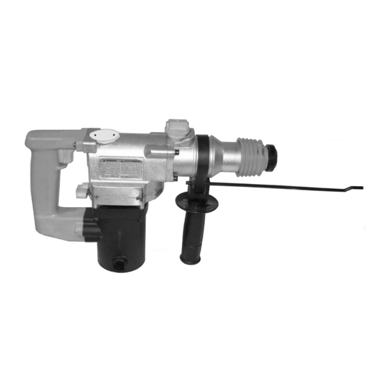
ROTARY HAMMER - 1"
SET up And OpERATing inSTRucTiOnS
Diagrams within this manual may not be drawn proportionally.
Due to continuing improvements, actual product may differ slightly from the product described herein.
distributed exclusively by Harbor Freight Tools
Visit our website at: http://www.harborfreight.com
Read this material before using this product.
Failure to do so can result in serious injury.
SAVE THiS MAnuAl.
©
Copyright
2008 by Harbor Freight Tools
manual or any artwork contained herein may be reproduced in any shape or form
without the express written consent of Harbor Freight Tools.
For technical questions or replacement parts, please call 1-800-444-3353.
Model
3491 Mission Oaks Blvd., Camarillo, CA 93011
97743
®
. All rights reserved. No portion of this
®
.
Advertisement
Table of Contents

Related Manuals for Chicago Electric 97743


Summary of Contents for Chicago Electric 97743
- Page 1 ROTARY HAMMER - 1” Model 97743 SET up And OpERATing inSTRucTiOnS Diagrams within this manual may not be drawn proportionally. Due to continuing improvements, actual product may differ slightly from the product described herein. ® distributed exclusively by Harbor Freight Tools 3491 Mission Oaks Blvd., Camarillo, CA 93011 Visit our website at: http://www.harborfreight.com Read this material before using this product.
-
Page 2: Important Safety Information
SAVE THiS MAnuAl nOTicE is used to address practices Keep this manual for the safety not related to personal injury. warnings and precautions, assembly, cAuTiOn, without operating, inspection, maintenance and the safety alert cleaning procedures. Write the product’s symbol, is used to address serial number in the back of the manual near practices not related to the assembly diagram (or month and year of... - Page 3 outlets will reduce risk of electric non-skid safety shoes, hard hat, or shock. hearing protection used for appropri- ate conditions will reduce personal Avoid body contact with grounded injuries. surfaces such as pipes, radiators, ranges and refrigerators. There is prevent unintentional starting. Ensure the switch is in the off-po- an increased risk of electric shock if sition before connecting to power...
- Page 4 power tool use and care and the work to be performed. Use of the power tool for operations do not force the power tool. use different from those intended could the correct power tool for your result in a hazardous situation. application.
- Page 5 can cause serious personal injury • Properly maintain and inspect to and/or property damage. avoid electrical shock. • Any power cord must be properly Do not allow the bit to stop while in grounded. Ground Fault Circuit the hole. Remove the bit while it is Interrupter (GFCI) should also be still rotating.
-
Page 6: Vibration Safety
abnormal vibration occurs, stop use Vibration Safety immediately. This tool vibrates during use. SAVE THESE Repeated or long-term exposure to vibration may cause temporary or inSTRucTiOnS. permanent physical injury, particularly to the hands, arms and shoulders. To reduce the risk of vibration-related gROunding injury: TO pREVEnT... -
Page 7: Double Insulated Tools: Tools With Two Prong Plugs
and three prong grounding plug. applicable standards of Underwriters The plug must be connected to a Laboratories, Inc., the Canadian properly grounded outlet. If the tool Standard Association, and the should electrically malfunction or National Electrical Code. (See break down, grounding provides a Outlets for 2-prong plug.) low resistance path to carry electricity Double insulated tools may be used... -
Page 8: Specifications
indicate it is acceptable for outdoor SpEciFicATiOnS use. Electrical 120 V~ / 60 Hz / 620 W Make sure the extension cord is Requirements 2-Prong, Polarized Power Plug properly wired and in good electrical Speed 0 750/min condition. Always replace a damaged Blows Per extension cord or have it repaired by 2920 BPM... -
Page 9: Setup Instructions
SET up inSTRucTiOnS Read the EnTiRE iMpORTAnT SAFETY inFORMATiOn section at the beginning of this manual including all text under subheadings therein before set up or use of this product. TO pREVEnT SERiOuS injuRY FROM AccidEnTAl OpERATiOn: Turn the power Switch (96) of the Rotary Hammer to its “OFF” position and unplug the tool from its electrical outlet before assembling or making any adjustments to the tool. -
Page 10: Tool Set Up
of the Depth Gauge at that spot. Tool Set up (See Figure A.) Adjusting The Auxiliary Handle: After the Depth Gauge (106) is placed in the desired position, turn The Auxiliary Handle (107) can be the Auxiliary Handle (107) clockwise placed in a variety of positions. -
Page 11: Workpiece And Work Area Set Up
side and a symbol for a Drill only on Secure loose workpieces using a vise the right side. (See Figure A.) or clamps (not included) to prevent movement while working. To drill only: • Set the Switching Knob (24) so that the symbol of There must not be hazardous the Hammer and Drill are facing objects, such as utility lines or foreign... - Page 12 To remove the Drill Bit, pull back on Store the Rotary Hammer in its the Spring (41) and pull out the Bit. Carrying Case (105) and keep the For optimal performance, always Case in a clean, dry, safe location out keep Drill Bits and Chisels sharp.
-
Page 13: Maintenance And Servicing
only needed beginning after about 50 MAinTEnAncE And hours of use. (See Figure A.) SERVicing TO cHAngE OR clEAn THE Procedures not specifically cARBOn BRuSHES: It may explained in this manual become necessary at sometime must be performed only by a to replace or clean the two qualified technician. -
Page 14: Troubleshooting
TROuBlESHOOTing problem possible causes probable Solutions Tool will not start. No power at outlet. Check power at outlet. Cord not connected. Check that cord is plugged in. Blown fuse or tripped circuit Replace fuse or reset circuit breaker. breaker. Motor does not Disrupted power supply. -
Page 15: Parts List
pARTS liST part # description Qty. part # description Qty. O-Ring Washer Steel Ball Bearing Cylinder Distance Ring Feather Key Distance Cover Piston Front Cover O-Ring O-Ring Spring Holder Spring Spring Steel Column Clutch Retainer Sleeve Third Gear O-Ring O-Ring O-Ring Piston Second Hammer... -
Page 16: Please Read The Following Carefully
pARTS liST (cOnTinuEd) part # description Qty. part # description Qty. Washer Left Handle Cover Spring Insulating Sleeve Clutch Shaft Switch Cover Center Cover Power Switch Bearing Cord Pressing Board Armature ST Screw (M4x16) Fan Guide Board Field Screw Right Handle Cover Washer ST Screw (M5x25) Bearing... -
Page 17: Assembly Diagram
ASSEMBlY diAgRAM 31 64 REV 09e SKU 97743 For technical questions, please call 1-800-444-3353. Page 17... -
Page 18: Limited 90-Day Warranty
liMiTEd 90 dAY WARRAnTY Harbor Freight Tools Co. makes every effort to assure that its products meet high quality and durability standards, and warrants to the original purchaser that this product is free from defects in materials and workmanship for the period of 90 days from the date of purchase.